 在芯片上集成温度和湿度感应

A new generation of devices is emerging that integrates temperature and humidity sensing alongside data converters and logic with sophisticated calibration. Integrating the sensor can reduce the complexity and reliability of the system and provide more protection for sensitive electronic designs, as demonstrated by the Si7005 from Silicon Labs.
Developments in CMOS process technology are opening up new opportunities for the designers of embedded systems. Adding low-K polymeric dielectrics into the design means capacitive humidity sensors can be built alongside integrated temperature sensors along with integrated heating elements. This combination provides a powerful way to reduce the size and complexity of a system.
However, this comes with new design considerations. While previous protection and calibration of the sensor was handled in a discrete part, now it is part of a more complex logic design. Although this has advantages for the calibration, it has challenges for the designers, especially for the new generation of devices that integrate both temperature and humidity sensors. There are also new ways for the parts to be specified, with the specification of the accuracy and measurement margins.
Designers now have to consider protection of the device during the reflow process, taking baking and hydrating of the device into account in the development of the system and how this impacts the accuracy of the sensor measurements both immediately and in the longer term.
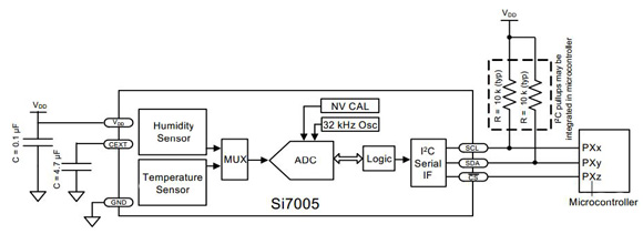
The Si7005 from Silicon Labs offers an accurate, low-power, factory-calibrated digital solution for measuring temperature, humidity, and dew point in applications ranging from air conditioning and asset tracking to industrial and consumer platforms.
The monolithic CMOS digital relative humidity and temperature sensor integrates temperature and humidity sensor elements, an analog-to-digital converter, signal processing, calibration data, and an I2C host interface. The patented use of industry-standard, low-K polymeric dielectrics for sensing humidity enables the construction of a low-power, monolithic CMOS sensor with low drift and hysteresis, and excellent long-term stability.
Both the temperature and humidity sensors are factory-calibrated and the calibration data is stored in the on-chip non-volatile memory. This ensures that the sensors are fully interchangeable, with no recalibration or software changes required.
Environmental protection is a key consideration for applications that use a humidity and temperature sensor, so an optional factory-installed protective cover offers a low profile, convenient means of protecting the sensor during assembly (for example during reflow soldering), and throughout the life of the product, excluding hydrophobic or oleophobic liquids and particulates.
While the Si7005 is largely a conventional mixed-signal CMOS integrated circuit, relative humidity sensors in general, and those based on capacitive sensing using polymeric dielectric, have unique application and use requirements that are not common to conventional non-integrated devices. The main issues are the need to protect the sensor during board assembly, and the need to subsequently rehydrate the sensor. There is also the need to protect the sensor from damage or contamination during the product lifecycle, and designers have to consider the impact of prolonged exposure to extremes of temperature and/or humidity and their potential effect on sensor accuracy. This is coupled with the issues of calibration and the effects of humidity sensor ‘memory’, as well as the need to apply temperature correction and linearization to the humidity readings.
Relative humidity sensor accuracy
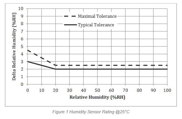
To determine the accuracy of a relative humidity sensor, it is placed in a temperature and humidity-controlled chamber. The temperature is set to a convenient fixed value (typically 30°C) and the relative humidity is swept from 20% to 80% and back to 20% in the following steps: 20% – 40% – 60% – 80% – 80% – 60% – 40% – 20%. At each set-point, the chamber is allowed to settle for a period of 30 minutes before a reading is taken from the sensor. Prior to the sweep, the device is allowed to stabilize to 50%RH. The RH accuracy is defined as the average of the two data points at each relative humidity set-point. In this case, the sensor shows an accuracy of 0.25%RH.
This provides an accuracy specification that includes unit-to-unit and lot-to-lot variation in non-linearity compensation, the accuracy of the factory calibration, and the margin for shifts that can occur during solder reflow (compensation for shift due to reflow is included in the linearization procedure below).
However, there are some limitations to the accuracy specification. It does not include hysteresis effects, which are typically ±1%, nor does it cover effects from long-term exposure to very humid conditions. Contamination of the sensor by particulates and chemicals can also have an effect. While the specification does not include variations due to temperature, once the temperature compensation is applied, the humidity readings will typically vary by less than ±0.05%/°C.
The capacitive relative humidity sensor in the Si7005 also needs linearization, and the accuracy specification applies after correction of non-linearity errors. The recommended linearization technique is to correct the measured relative humidity value with a second-order polynomial; the linear relative humidity (RH) value is calculated from the formula in Figure 2.
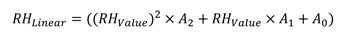
Figure 2: Linearization of the relative humidity value, where RHLinear is the corrected relative humidity value in %RH, RHValue is the uncorrected (measured) relative humidity value in %RH, and A2, A1, and A0 are unit-less correction coefficients derived through characterization of Si7005s by Silicon Labs; their values depend on whether compensation for a typical solder reflow is required.
The humidity sensor is calibrated at a temperature of 30°C as the sensor will give the most accurate relative humidity readings. For relative humidity measurements at other temperatures, the RH reading from the Si7005 must be compensated for the change in temperature relative to 30°C, using the values from the integrated temperature sensors. This makes the compensation process relatively simple and self-contained within the device.
Temperature compensated relative humidity readings can be calculated from the formula in Figure 3.

Figure 3: Temperature compensation for the Si7005, where RHTempCompensated is the temperature compensated relative humidity value in %RH and RHLinear is the linear corrected relative humidity value in %RH. Temperature is the ambient temperature in °C as measured by the Si7005 on-chip temperature sensor and Q1 and Q0 are unit-less correction coefficients derived through characterization of Si7005s by Silicon Labs. This temperature compensation is most accurate in the range of 15–50°C.
The Si7005 relative humidity sensor contains an integrated, resistive heating element that may be used to raise the temperature of the humidity sensor. This element can be used to drive off condensation or to implement dew point measurement when the Si7005 is used in conjunction with a separate temperature sensor such as another Si7005.
The heater can be activated by setting the D1 HEAT bit in the CONFIG register (register 0x03). Turning on the heater will reduce the tendency of the humidity sensor to accumulate an offset due to "memory" of sustained high humidity conditions. When the heater is enabled, the reading of the on-chip temperature sensor will be increased.
Hysteresis
The moisture absorbent film (polymeric dielectric) of the humidity sensor will carry a memory of its exposure history, particularly its recent or extreme exposure history. A sensor exposed to relatively low humidity will carry a negative offset relative to the factory calibration, and a sensor exposed to relatively high humidity will carry a positive offset relative to the factory calibration. This factor causes a hysteresis effect, the difference in %RH between the maximum absolute error on the decreasing humidity ramp and the maximum absolute error on the increasing humidity ramp at a single relative humidity set-point. This is expressed as a bipolar quantity relative to the average.
Prolonged exposure to high humidity will result in a gradual upward drift of the RH reading. The shift in sensor reading resulting from this drift will generally disappear slowly under normal ambient conditions. The amount of shift is proportional to the magnitude of relative humidity and the length of exposure. In the case of lengthy exposure to high humidity, some of the resulting shift may persist indefinitely under typical conditions. It is generally possible to substantially reverse this effect by baking the device.
Si7005 devices are shipped, like most ICs, vacuum-packed with an enclosed desiccant to avoid any drift during storage, as well as to prevent any moisture-related issues during solder reflow. Devices should be soldered using reflow and a ‘no clean’ solder process, as a water or solvent rinse after soldering will affect accuracy.
The measured humidity value will generally shift slightly after solder reflow. This shift is accounted for when using the linearization procedure given above. After soldering, the Si7005 should be allowed to equilibrate under controlled RH conditions (room temperature, 45–55%RH) for at least 48 hours to reach rated accuracy. During soldering, it is recommended that a protective cover of some kind be in place such as Kapton polyimide tape. Hot air rework is not recommended and soldering iron touch-up is possible if flux is not needed and care is taken to avoid excessive heating. If rework is required, the part can be removed by hot air and a new part soldered on by reflow.
Alternatively, Si7005s may be ordered with a factory fitted, solder-resistant protective cover which can be left in place for the lifetime of the product, preventing liquids, dust or other contaminants from coming into contact with the polymer sensor film.
Protecting the sensor
When the sensor operates on the principle of measuring a change in capacitance, any changes to the dielectric constant of the polymer film will be detected as a change in relative humidity. Therefore, it is important to minimize the probability of contaminants coming into contact with the sensor. Dust and other particles, as well as liquids can affect the RH reading. It is recommended that a filter cover be employed in the end system that blocks contaminants, but also allows water vapor to pass through. Depending on the needs of the application, this can be as simple as plastic or metallic gauze for basic protection against particulates, or something more sophisticated such as a hydrophobic membrane providing up to IP67 compliant protection.
As mentioned earlier, Si7005s may be ordered with a factory fitted, solder-resistant cover, which can be left in place for the lifetime of the product. It is very low profile, hydrophobic and oleophobic, and excludes particulates down to 0.35 microns in size. The sensor should also be protected from direct sunlight to prevent heating effects as well as possible material degradation.
After exposure to extremes of temperature and/or humidity for prolonged periods, the polymer sensor film can become either very dry or very wet; in each case the result is either high or low relative humidity readings. Under normal operating conditions, the induced error will diminish over time. From a very dry condition, such as after shipment and soldering, the error will diminish over a few days at typical controlled ambient conditions, for example, 48 hours of 45 ≤ %RH ≤ 55. However, from a very wet condition, recovery may take significantly longer. To accelerate recovery from a wet condition, a bake and hydrate cycle can be implemented. This operation consists of baking the sensor at 125°C for over 12 hours, followed by hydration at 30°C in 75%RH for 10 hours. Following this cycle, the sensor will return to normal operation in typical ambient conditions after a few days.
Long term drift/aging
Over long periods of time, the sensor readings may drift due to aging of the device. Standard accelerated life testing of the Si7005 has resulted in the specifications for long-term drift shown in Table 4 and Table 5 of the datasheet. This contribution to the overall sensor accuracy accounts only for the long-term aging of the device in an otherwise benign operating environment and does not include the effects of damage, contamination, or exposure to extreme environmental conditions.
Development support
A suite of hardware and software development tools for testing, characterization, prototyping, and software development is available to support the Si7005.
The Si7005USB-DONGLE Evaluation Kit comes with everything developers need to demonstrate and evaluate the Si7005. The board plugs into a PC via a USB socket and has a connector for adding the Si7005USB-EVB. This is a small daughter card that permits evaluation of the Si7005 at the end of a flex cable.
The Si7005EVB-UDP is a small daughter card for evaluating the Si7005 in conjunction with certain Unified Development Platform (UDP) components such as the C8051F960 Ultra-Low-Power Microcontroller Development Kit. It plugs directly into UDP MCU cards for fast prototyping and software development. Alongside the Si7005, there is also a connector for adding a Si7005-EVB via its flex cable, allowing the user to place the Si7005 in a temperature/humidity chamber or a product prototype.
The Si7005EVB-UDP-F960 Development Kit combines the C8051F960 Ultra-Low-Power Microcontroller Development Kit and the Si7005EVB-UDP daughter card with data-logger demonstration code. It is a complete package designed to support hardware and software development using the Si7005 and Silicon Labs’ ultra-low-power MCUs. It ships with example software that implements a portable, battery-powered data logger or asset tracker.
Figure 4: The development systems for the Si7005.
Conclusion
The development of new process technology has provided a highly-integrated device with temperature and humidity sensing, as well as heating elements controlled directly from the internal registers. This provides smaller, lower cost designs, but also means having to pay more attention to the manufacturing and long term stability of the system.
声明:本文内容及配图由入驻作者撰写或者入驻合作网站授权转载。文章观点仅代表作者本人,不代表电子发烧友网立场。文章及其配图仅供工程师学习之用,如有内容侵权或者其他违规问题,请联系本站处理。
举报投诉
发布评论请先 登录
相关推荐
热点推荐
三星电容X7R介质在光伏逆变器中的长期湿度稳定性
对可靠性的严苛要求。 一、X7R介质的核心特性与湿度稳定性的关联 1、温度稳定性基础 X7R介质属于温度稳定型陶瓷电容器,在-55℃至+125℃范围内容量变化率≤±15%。这一特性为
深入解析Microchip EMC1704:高侧电流感应与多通道温度监测的理想之选
深入解析Microchip EMC1704:高侧电流感应与多通道温度监测的理想之选 在电子设备的设计中,精确的电流和温度监测至关重要。Microchip的EMC1704作为一款集高侧电
高性能温度传感器IC的主要应用场景
在先进的自动雨量感应系统中,温度传感器IC与湿度传感芯片协同工作,通过监测前挡风玻璃上的雨滴状态,实时判断降雨强度。系统根据传感器采集到的信号,自动启动雨刮器并智能调节刮刷频率,确保驾

探索 MAX1978/MAX1979:高效的珀尔帖模块集成温度控制器
产品概述 MAX1978/MAX1979是专为珀尔帖模块设计的集成温度控制器,具有诸多出色特性。芯片上集成了功率
HDC1080:低功耗高精度数字湿度与温度传感器的卓越之选
湿度传感器,它集成了温度传感器,以其低功耗和高精度的特点,在众多应用领域中脱颖而出。 文件下载: hdc1080.pdf 一、HDC1080 核心特性 高精度测量 HDC1080
HDC1010数字湿度与温度传感器:精确、低功耗的环境感知利器
HDC1010数字湿度与温度传感器:精确、低功耗的环境感知利器 在环境监测和控制应用领域,精确测量湿度和温度是实现高效、智能系统的关键。德州
【奥伟斯OWEIS】ICman晶尊微触摸感应芯片、液位检测芯片、接近感应芯片、人体感应芯片应用方案全解析
,是一系列专业芯片的精密协作。厦门晶尊微电子有限公司(ICman)深耕电容感应技术多年,在感应芯片领域形成了多个完整且成熟的解决方案。这些方

中国科大实现电泵浦片上集成高亮度纠缠量子光源
。 中国科学技术大学教授潘建伟、张强等组成的研究团队与济南量子技术研究院、中国科学院半导体所等单位合作,通过混合集成分布式反馈激光器与薄膜铌酸锂光子芯片,成功实现了电泵浦、片上集成的高亮度偏振纠缠源,向
数字单总线输出,可长距离串联多个节点的温湿度传感芯片-MHT04
温湿度传感芯片是一种可以检测环境温度和相对湿度的传感器,通常由一个传感器元件、一个模拟-数字转换器和一个处理器组成。这些部件在一起工作,可以测量环境中的

新升级高精度温湿度传感器芯片GXHTV4分享
在环境监测、设备控制与智能系统设计中,温湿度传感器芯片的性能与可靠性往往直接影响整体方案的成败。英尚微今天分享一款在业内备受关注的高集成度芯片
温湿度传感器HTU31D在温湿度控器中的应用优势
温湿度控制器是一种用于监测和调节环境温度与湿度的设备,广泛应用于农业、仓储、工业生产、家庭等多个领域。其主要功能是维持特定环境条件,以确保产品质量和舒适的居住环境。 温湿度控制器的工作
E-GaN电源芯片U8733L集成外置温度检测和恒功率功能
E-GaN电源芯片U8733L集成外置温度检测和恒功率功能Yinlianbao开关电源NTC传感器能够感知微小的温度变化,一旦温度超过预设的

沐渥氮气柜控制面板湿度与温度报警功能详述
氮气柜控制面板的湿度与温度报警功能主要用于确保柜内环境稳定,防止敏感物料因环境波动而受损。低湿报警功能:当柜内湿度低于设定下限时触发报警。某些物料需要维持最低湿度,
应用在农业环境温度监测中的高精度数字温度传感芯片
农业环境温度监测的工作原理主要依赖于各种传感器技术,特别是温湿度传感器和土壤温度检测仪。这些设备通过测量环境中的温度、湿度等参数,实时采


评论