 电池欠压告警器(英文),Battery Low Voltage Alarm

电池欠压告警器(英文),Battery Low Voltage Alarm
关键字:电池欠压告警器
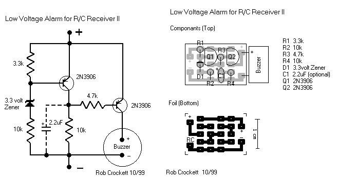
Here is another equally cool low voltage alarm circuit for your glider receiver battery that I've shamelessly stolen from George Steiner's book "A to Z--Radio Control Electronic Journal" (see below). I've modified it to use with small battery packs in R/C gliders. This design has a trigger voltage at about 4.3 volts, and it draws 1mA or less when quiet and about 4mA when buzzing. This can be constructed from parts fromt Radio Shack, though you may need to order a few through them.
The voltage of a receiver system is punctuated by low-voltage spikes every time the servo motors spin up, since the servos draw more than the battery can deliver. With large receiver battery packs, this is not as much of an issue, and it may not be noticeable. However with 270mA and smaller battery packs, particularly with more than two servos, low voltage alarms can chirp constantly, every time a servo moves. The challenge is to design in a little slack or delay, just enough so that you are not annoyed by constant chirping, but not too much so that the chirps can give you a warning before the battery is completely exhausted. Here, this "hysteresis" is adjusted with the capacitor. For large packs (600mA and above), no capacitor is probably needed, although I've been using a 1uF capacitor on my open class ship with 6 servos and a 600mA battery. For 270 mA and two servos, I'd suggest trying a 1uF capacitor. For 150mA or less, a 2.2uF capacitor works well. If you want to know only when the battery has finally reached the trigger voltage, try a 5uF (or 4.7uF) capacitor. The actual type of capacitor is not critical, but tantalum capacitors are physically smaller. If you want to worry about the polarity of the capacitor, the negative side should be directed toward the negative pole of the battery, but at these relatively low voltages compared to the capacitor rating, the polarity probably does not matter.
This circuit is set up for a four cell receiver battery pack at a trigger voltage of about 4.3 volts (about 1.1volts/cell). You can adjust R1 (here a 3.3k resistor) to change the trigger voltage of the circuit. For example, for a 5 cell pack, to change the trigger voltage to 5.5 volts, change R1 to 2.2k. For a three cell pack, to change the trigger voltage to 3.3 volts, change R1 to 6.8 k (or use two 3.3k resistors in parallel by soldering a resistor in each hole and twisting together the top leads). Because of slight variability in tolerances of the componants, you should check this little device with a variable power source and a voltmeter to confirm its trigger point. Alternately, use your digital voltmeter or expanded scale voltmeter to calibrate its chirp pattern by measuring the voltage of the onboard battery pack intermittently as you fly.
Make sure the band on the Zener diode is toward the "+" side (toward R1). Solder a battery connector or servo connector to the board with positive and negative as shown, and plug the connector into an unused slot in your receiver.
Circuit diagram
Radio Shack parts: Here again, you can use smaller rated resistors if you can get them--1/8 watt or less is fine. Tantalum capacitors are physically smaller, but any composition will work.
273-074 Miniature Piezo Buzzer, 12v, PC board mount
271-312 1/4 watt 5% carbon film resistors, 500 pieces (Take the plunge!)
276-1604 Package of 15 PNP small signal 2N3906-type transistors. Could use instead 276-2016 $0.59 2N3904 PNP transistors
RSU 11673505 3.3v Zener diode (not on shelf--need to order 1-800-THE-SHACK)
272-1434 1uf tantalum capacitor (see above for choice of capacitor)
RSU 11295888 2.2uF tantalum capacitor (not on shelf--need to order)
272-1024 4.7uF radial-lead electrolytic capacitor
Digikey (1-800-344-4539) part numbers: Digikey does sell the peizo buzzers, but they are much more expensive than those at Radio Shack and are larger as well.
2N3906-ND PNP general purpose amp/switch transistor
1N5226BMSCT-ND 3.3v Zener diode 500mA
3.3KEBK-ND 1/8 watt resistors
4.7KEBK-ND 1/8 watt resistors
10KEBK-ND 1/8 watt resistors
P2105-ND 1.0uF Tantalum capacitor 16volt
P2022-ND 2.2uF Tantalum capacitor 10volt
P2024-ND 4.7uF Tantalum capacitor 10 volt
FP012C-5-ND 3M clear 0.5" heat shrink tubing, 5 feet
George Steiner's book, crammed with cool R/C radio info, can be had for $19.95 postage paid from the following:
GSP AZ Journal
2238 Rogue River Drive
Sacramento CA 95826
phone: 916-362-1962
Author: Rob Crockett 10/99 GSP AZ Journal
2238 Rogue River Drive
Sacramento CA 95826
phone: 916-362-1962
声明:本文内容及配图由入驻作者撰写或者入驻合作网站授权转载。文章观点仅代表作者本人,不代表电子发烧友网立场。文章及其配图仅供工程师学习之用,如有内容侵权或者其他违规问题,请联系本站处理。
举报投诉
发布评论请先 登录
相关推荐
热点推荐
变频器报母线欠压故障是怎么原因?如何解决?
变频器报“直流母线欠压”故障,本质是内部直流电路的电压降到了阈值以下。这通常由三个层面的原因引起: 输入电源问题 、 负载或加速过快问题 ,以及 变频器内部硬件问题 。 你可以按照以下

MC33774 AFE 不重置ALARM_OUT是怎么回事?
你好,我正在使用MC33774A,但在重置寄存器事件“FEH
ALARM_OUT_REASONO”时遇到了问题。
在数据表中阅读如何通过在两个寄存器中执行 READ作来重置 ALARM
发表于 04-07 07:35
探索LTC4367:高性能过压、欠压及反接保护控制器
探索LTC4367:高性能过压、欠压及反接保护控制器 在电子系统设计中,电源输入的稳定性和安全性至关重要。电源电压过高、过低或极性接反等问题,都可能对系统造成严重损害。为了解决这些问题
SiLM27517HAD-7G 20V, 4A/5A单通道高欠压保护低边门极驱动器
SiLM27517HAD-7G是一款具备高欠压保护阈值的单通道低边栅极驱动器,采用超紧凑的SOT23-5封装。它设计用于驱动MOSFET和IGBT,其工作电压范围为13.5V至20V,在15V供电
发表于 01-24 09:23
高欠压保护驱动器SiLM27511HAC-AQ以12.5V欠压锁定提升驱动电路可靠性
概述:
在工业与汽车电子系统中,电源网络的波动可能直接导致驱动电路失效,甚至损坏后级昂贵的功率器件。传统驱动器的欠压保护点较低,在电压跌落时难以及时响应。SiLM27511HAC-AQ高欠
发表于 01-14 08:28
硅负极电池供电新选择--帝奥微DIO6156 低UVLO(欠压锁定)+全维度高性能同步降压DCDC
了革命性的突破。但硅负极电池的部分容量需要通过更低的放电电压实现,因此,对在手机应用上配套的DC/DC转换器提出了“更低UVLO(欠压锁定)”的核心需求。 帝奥微近期推出的同步降压DC
使用alarm模块的时候,设置时间之后没有更新新的alarm时间是为什么?
你好,我使用的是rt-thread studio 2.2.6,在STM32F407VG芯片上使用RT-THREAD的标准版本4.1.1。
在使用提供的alarm模块时,设置了一个每分钟触发
发表于 09-29 07:45
这种AC-DC的电源过压保护是否需要增加?如何设计过压保护电路?欠压保护芯片是自带的HV脚
这种AC-DC的电源过压保护是否需要增加?如何设计过压保护电路?欠压保护芯片是自带的HV脚
发表于 09-25 10:57
英飞凌9954系列设定VS过压欠压,过温的寄存器的门限值设定没有找到,请问怎么设置?
英飞凌9954系列设定VS过压欠压,过温的寄存器的门限值设定没有找到,请问下怎么设置?
发表于 08-05 08:23
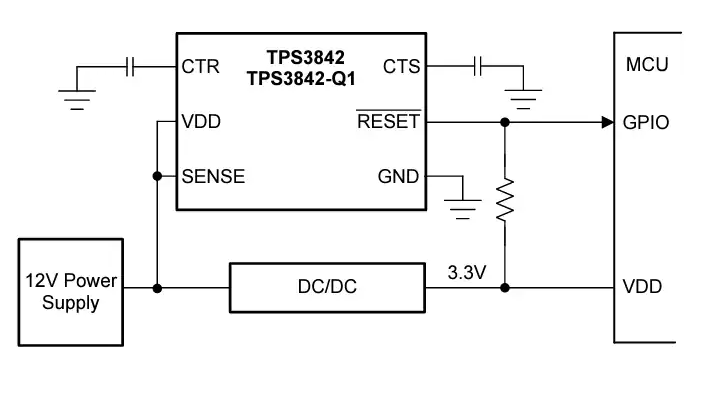
Texas Instruments TPS3842/TPS3842-Q1欠压监控器数据手册
Texas Instruments TPS3842/TPS3842-Q1欠压监控器具有1.5%精度、快速检测时间和850nA电源电流。42V输入电压监控器直接连接到12V电池,以连续监
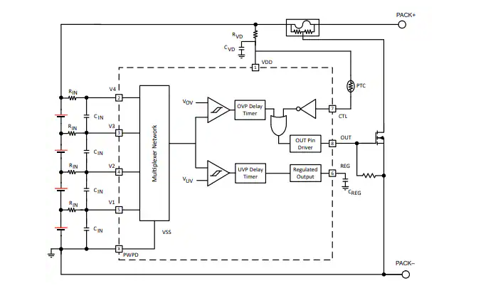
Texas Instruments BQ2969T过压和过热保护器数据手册
情况的单独监控。当检测到任何电池上的过压时,会启动内部固定延迟定时器。BQ2969T保护器具有自禁用功能,可在电池电压降至可编程欠
LTC4365的过欠压设置电阻是否可以通过输出电压来改变?
您好,我想使用LTC4365在设定过欠压值时,一开始设定一个较窄的允许范围,上电以后实现一个较宽的电压范围,目的是防止后端可能有大的脉冲负载,电压可能短时间内会降低的比较多,想用大的电压范围来扛过去,想请教一下是否可以这样使用
发表于 07-14 07:00
快充电源芯片U872XAH系列的欠压过压保护功能
欠压保护是指当输入电压低于预设阈值时,自动切断电源输出,避免设备在低压下异常工作或损坏;过压保护是指输入电压超过安全限值时,立即切断输入或关闭输出,防止高压击穿元件。快充电源芯片U872XAH系列有三个档位,输入、输出都具备
【RA4L1-SENSOR】评测任务一:干电池电量检测器
)
* (voltage - v_low) / (v_high - v_low);
}
}
return 100;
}
四、系统工作流程
Battery: 静置15分钟后测量
发表于 06-27 18:04


评论