 ZYNQ SOC案例开发:AXI DMA使用解析及环路测试

一、AXI DMA介绍
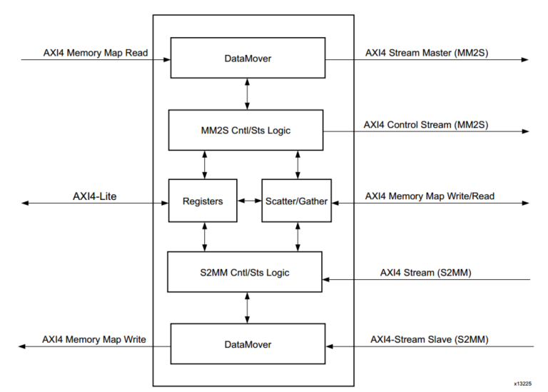
本篇博文讲述AXI DMA的一些使用总结,硬件IP子系统搭建与SDK C代码封装参考米联客ZYNQ教程。若想让ZYNQ的PS与PL两部分高速数据传输,需要利用PS的HP(高性能)接口通过AXI_DMA完成数据搬移,这正符合PG021 AXI DMA v7.1 LogiCORE IP Product Guide中介绍的AXI DMA的应用场景:The AXI DMA provides high-speed data movement between system memory and an AXI4-Stream-based target IP such as AXI Ethernet.
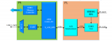
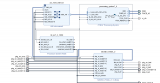
如图,AXI DMA主要包括Memory Map和 Stream两部分接口,前者连接PS子系统,后者则连接带有流接口的PL IP核。
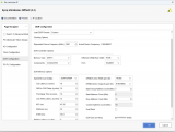
其最简单的事直接寄存器模式(Simple DMA),这里需要注意地址对齐的问题:当没有使能地址重对齐的情况下,如果AXI Memory Map数据位宽是32bit,则搬移数据所在地址必须在0x0,0x4,0x8等起始地址上。接下来关注DMA IP核配置界面主要参数:
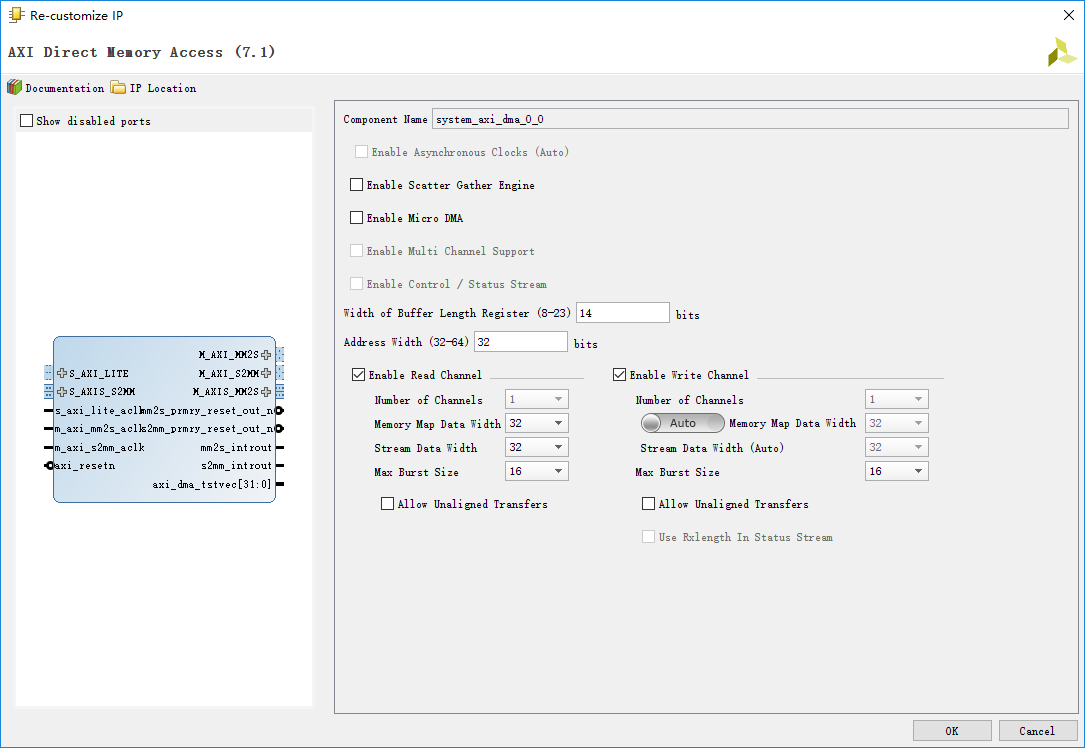
AXI DMA可以有两个传输方向:读通道和写通道,依次为MM2S和S2MM方向。也就是说“读”和“写”是DMA主动对CPU发起的操作。重点查看以下几个参数:
1 Width of Buffer Length Register:
在直接寄存器模式下,它指定在MM2S_LENGTH和S2MM_LENGTH寄存器的有效比特数。MM2S_LENGTH寄存器指定了MM2S通道传输数据字节数,当CPU写入非零值时开始进行PS到PL的数据搬移,而S2MM_LENGTH对应另一个数据流方向。比特数直接与对应寄存器可写入的最大数直接相关,传输最大字节数= 2^(Width of Buffer Length Register)。此处保持默认14bit,也就是说启动DMA传输的最大数据量是16384byte。
2 Memory Map Data Width:
该参数指定了Memory Map侧数据接口宽度,选定32bit后搬移数据所在内存地址必须与4对齐。
3 Max Burst Size:
之前在讲解PS子系统内部的DMA时介绍过DMA的Burst概念,即分批次传输数据块。官方IP核文档解释为:
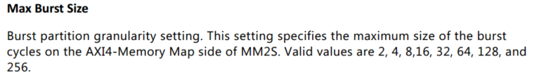
理解起来burst size确定了突发周期的最大数值,也就是burst size越大,突发粒度越大(单次传输的数据个数越多)。这与PS端DMA有所区别,显然与 PS DMA的burst length意义相近。笔者也进行过尝试,当启动传输数据量相同时,burst size设置较大情况下,每批次传输数据量更多。
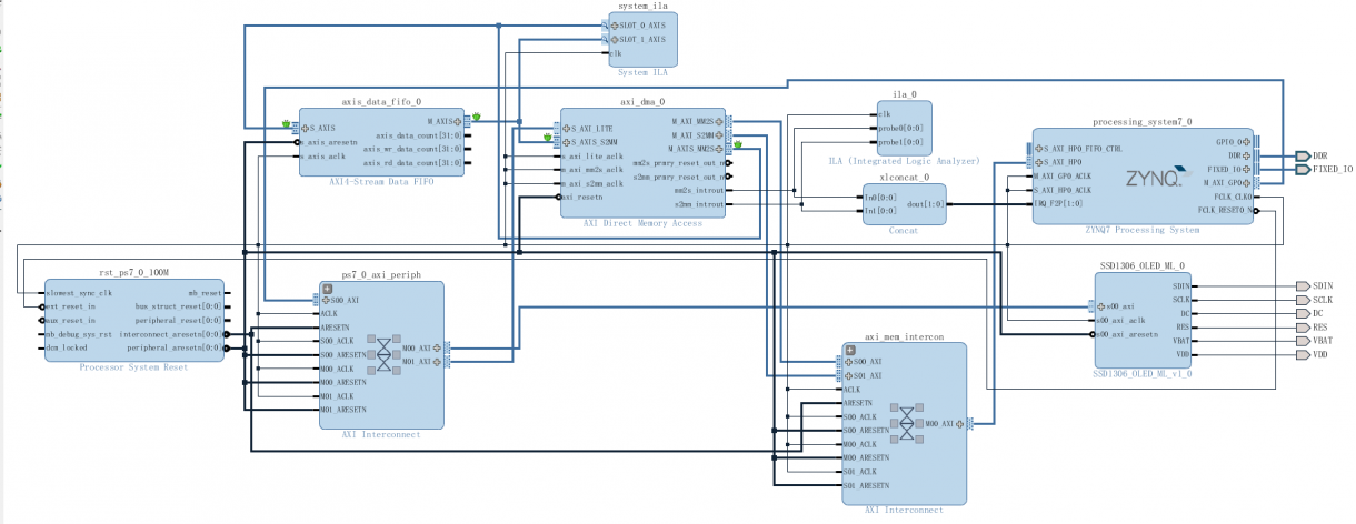
二、AXI DMA Loop IP子系统
在利用ZYNQ搭建系统时,经常需要利用各种IP核做所谓的“计算加速”,将重复性高 计算量大 占用较大CPU资源的底层处理交给各个IP核完成。这时PS ->DMA ->PL -> DMA -> PS的环路架构非常适用。这里使用AXI Stream Data FIFO代替自定义IP核作为演示,硬件IP子系统如下:
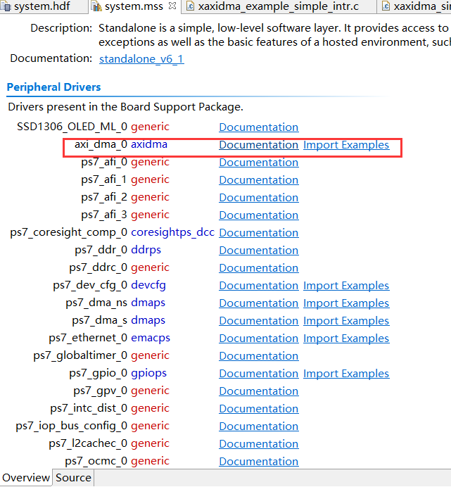
三、SDK 官方demo解析
首先分析下官方的demo。
/******************************************************************************
*
* Copyright (C) 2010 - 2016 Xilinx, Inc. All rights reserved.
*
* Permission is hereby granted, free of charge, to any person obtaining a copy
* of this software and associated documentation files (the "Software"), to deal
* in the Software without restriction, including without limitation the rights
* to use, copy, modify, merge, publish, distribute, sublicense, and/or sell
* copies of the Software, and to permit persons to whom the Software is
* furnished to do so, subject to the following conditions:
*
* The above copyright notice and this permission notice shall be included in
* all copies or substantial portions of the Software.
*
* Use of the Software is limited solely to applications:
* (a) running on a Xilinx device, or
* (b) that interact with a Xilinx device through a bus or interconnect.
*
* THE SOFTWARE IS PROVIDED "AS IS", WITHOUT WARRANTY OF ANY KIND, EXPRESS OR
* IMPLIED, INCLUDING BUT NOT LIMITED TO THE WARRANTIES OF MERCHANTABILITY,
* FITNESS FOR A PARTICULAR PURPOSE AND NONINFRINGEMENT. IN NO EVENT SHALL
* XILINX BE LIABLE FOR ANY CLAIM, DAMAGES OR OTHER LIABILITY,
* WHETHER IN AN ACTION OF CONTRACT, TORT OR OTHERWISE, ARISING FROM, OUT OF
* OR IN CONNECTION WITH THE SOFTWARE OR THE USE OR OTHER DEALINGS IN THE
* SOFTWARE.
*
* Except as contained in this notice, the name of the Xilinx shall not be used
* in advertising or otherwise to promote the sale, use or other dealings in
* this Software without prior written authorization from Xilinx.
*
******************************************************************************/
/*****************************************************************************/
/**
*
* @file xaxidma_example_simple_intr.c
*
* This file demonstrates how to use the xaxidma driver on the Xilinx AXI
* DMA core (AXIDMA) to transfer packets.in interrupt mode when the AXIDMA core
* is configured in simple mode
*
* This code assumes a loopback hardware widget is connected to the AXI DMA
* core for data packet loopback.
*
* To see the debug print, you need a Uart16550 or uartlite in your system,
* and please set "-DDEBUG" in your compiler options. You need to rebuild your
* software executable.
*
* Make sure that MEMORY_BASE is defined properly as per the HW system. The
* h/w system built in Area mode has a maximum DDR memory limit of 64MB. In
* throughput mode, it is 512MB. These limits are need to ensured for
* proper operation of this code.
*
*
*
 * MODIFICATION HISTORY:
 *
 * Ver   Who  Date     Changes
 * ----- ---- -------- -------------------------------------------------------
 * 4.00a rkv  02/22/11 New example created for simple DMA, this example is for
 *                  simple DMA,Added interrupt support for Zynq.
 * 4.00a srt  08/04/11 Changed a typo in the RxIntrHandler, changed
 *               XAXIDMA_DMA_TO_DEVICE to XAXIDMA_DEVICE_TO_DMA
 * 5.00a srt  03/06/12 Added Flushing and Invalidation of Caches to fix CRs
 *               648103, 648701.
 *               Added V7 DDR Base Address to fix CR 649405.
 * 6.00a srt  03/27/12 Changed API calls to support MCDMA driver.
 * 7.00a srt  06/18/12 API calls are reverted back for backward compatibility.
 * 7.01a srt  11/02/12 Buffer sizes (Tx and Rx) are modified to meet maximum
 *               DDR memory limit of the h/w system built with Area mode
 * 7.02a srt  03/01/13 Updated DDR base address for IPI designs (CR 703656).
 * 9.1   adk  01/07/16 Updated DDR base address for Ultrascale (CR 799532) and
 *               removed the defines for S6/V6.
 * 9.2   vak  15/04/16 Fixed compilation warnings in the example
 *
*
* ***************************************************************************
*/
/***************************** Include Files *********************************/
#include "xaxidma.h"
#include "xparameters.h"
#include "xil_exception.h"
#include "xdebug.h"
#ifdef XPAR_UARTNS550_0_BASEADDR
#include "xuartns550_l.h" /* to use uartns550 */
#endif
#ifdef XPAR_INTC_0_DEVICE_ID
#include "xintc.h"
#else
#include "xscugic.h"
#endif
/************************** Constant Definitions *****************************/
/*
* Device hardware build related constants.
*/
#define DMA_DEV_ID XPAR_AXIDMA_0_DEVICE_ID
#ifdef XPAR_AXI_7SDDR_0_S_AXI_BASEADDR
#define DDR_BASE_ADDR XPAR_AXI_7SDDR_0_S_AXI_BASEADDR
#elif XPAR_MIG7SERIES_0_BASEADDR
#define DDR_BASE_ADDR XPAR_MIG7SERIES_0_BASEADDR
#elif XPAR_MIG_0_BASEADDR
#define DDR_BASE_ADDR XPAR_MIG_0_BASEADDR
#elif XPAR_PSU_DDR_0_S_AXI_BASEADDR
#define DDR_BASE_ADDR XPAR_PSU_DDR_0_S_AXI_BASEADDR
#endif
#ifndef DDR_BASE_ADDR
#warning CHECK FOR THE VALID DDR ADDRESS IN XPARAMETERS.H, /
DEFAULT SET TO 0x01000000
#define MEM_BASE_ADDR 0x01000000
#else
#define MEM_BASE_ADDR (DDR_BASE_ADDR + 0x1000000)
#endif
#ifdef XPAR_INTC_0_DEVICE_ID
#define RX_INTR_ID XPAR_INTC_0_AXIDMA_0_S2MM_INTROUT_VEC_ID
#define TX_INTR_ID XPAR_INTC_0_AXIDMA_0_MM2S_INTROUT_VEC_ID
#else
#define RX_INTR_ID XPAR_FABRIC_AXIDMA_0_S2MM_INTROUT_VEC_ID
#define TX_INTR_ID XPAR_FABRIC_AXIDMA_0_MM2S_INTROUT_VEC_ID
#endif
#define TX_BUFFER_BASE (MEM_BASE_ADDR + 0x00100000)
#define RX_BUFFER_BASE (MEM_BASE_ADDR + 0x00300000)
#define RX_BUFFER_HIGH (MEM_BASE_ADDR + 0x004FFFFF)
#ifdef XPAR_INTC_0_DEVICE_ID
#define INTC_DEVICE_ID XPAR_INTC_0_DEVICE_ID
#else
#define INTC_DEVICE_ID XPAR_SCUGIC_SINGLE_DEVICE_ID
#endif
#ifdef XPAR_INTC_0_DEVICE_ID
#define INTC XIntc
#define INTC_HANDLER XIntc_InterruptHandler
#else
#define INTC XScuGic
#define INTC_HANDLER XScuGic_InterruptHandler
#endif
/* Timeout loop counter for reset
*/
#define RESET_TIMEOUT_COUNTER 10000
#define TEST_START_VALUE 0xC
/*
* Buffer and Buffer Descriptor related constant definition
*/
#define MAX_PKT_LEN 0x100
#define NUMBER_OF_TRANSFERS 10
/* The interrupt coalescing threshold and delay timer threshold
* Valid range is 1 to 255
*
* We set the coalescing threshold to be the total number of packets.
* The receive side will only get one completion interrupt for this example.
*/
/**************************** Type Definitions *******************************/
/***************** Macros (Inline Functions) Definitions *********************/
/************************** Function Prototypes ******************************/
#ifndef DEBUG
extern void xil_printf(const char *format, ...);
#endif
#ifdef XPAR_UARTNS550_0_BASEADDR
static void Uart550_Setup(void);
#endif
static int CheckData(int Length, u8 StartValue);
static void TxIntrHandler(void *Callback);
static void RxIntrHandler(void *Callback);
static int SetupIntrSystem(INTC * IntcInstancePtr,
XAxiDma * AxiDmaPtr, u16 TxIntrId, u16 RxIntrId);
static void DisableIntrSystem(INTC * IntcInstancePtr,
u16 TxIntrId, u16 RxIntrId);
/************************** Variable Definitions *****************************/
/*
* Device instance definitions
*/
static XAxiDma AxiDma; /* Instance of the XAxiDma */
static INTC Intc; /* Instance of the Interrupt Controller */
/*
* Flags interrupt handlers use to notify the application context the events.
*/
volatile int TxDone;
volatile int RxDone;
volatile int Error;
/*****************************************************************************/
/**
*
* Main function
*
* This function is the main entry of the interrupt test. It does the following:
* Set up the output terminal if UART16550 is in the hardware build
* Initialize the DMA engine
* Set up Tx and Rx channels
* Set up the interrupt system for the Tx and Rx interrupts
* Submit a transfer
* Wait for the transfer to finish
* Check transfer status
* Disable Tx and Rx interrupts
* Print test status and exit
*
* @param None
*
* @return
* - XST_SUCCESS if example finishes successfully
* - XST_FAILURE if example fails.
*
* @note None.
*
******************************************************************************/
int main(void)
{
int Status;
XAxiDma_Config *Config;
int Tries = NUMBER_OF_TRANSFERS;
int Index;
u8 *TxBufferPtr;
u8 *RxBufferPtr;
u8 Value;
TxBufferPtr = (u8 *)TX_BUFFER_BASE ;
RxBufferPtr = (u8 *)RX_BUFFER_BASE;
/* Initial setup for Uart16550 */
#ifdef XPAR_UARTNS550_0_BASEADDR
Uart550_Setup();
#endif
xil_printf("/r/n--- Entering main() --- /r/n");
Config = XAxiDma_LookupConfig(DMA_DEV_ID);
if (!Config) {
xil_printf("No config found for %d/r/n", DMA_DEV_ID);
return XST_FAILURE;
}
/* Initialize DMA engine */
Status = XAxiDma_CfgInitialize(&AxiDma, Config);
if (Status != XST_SUCCESS) {
xil_printf("Initialization failed %d/r/n", Status);
return XST_FAILURE;
}
if(XAxiDma_HasSg(&AxiDma)){
xil_printf("Device configured as SG mode /r/n");
return XST_FAILURE;
}
/* Set up Interrupt system */
Status = SetupIntrSystem(&Intc, &AxiDma, TX_INTR_ID, RX_INTR_ID);
if (Status != XST_SUCCESS) {
xil_printf("Failed intr setup/r/n");
return XST_FAILURE;
}
/* Disable all interrupts before setup */
XAxiDma_IntrDisable(&AxiDma, XAXIDMA_IRQ_ALL_MASK,
XAXIDMA_DMA_TO_DEVICE);
XAxiDma_IntrDisable(&AxiDma, XAXIDMA_IRQ_ALL_MASK,
XAXIDMA_DEVICE_TO_DMA);
/* Enable all interrupts */
XAxiDma_IntrEnable(&AxiDma, XAXIDMA_IRQ_ALL_MASK,
XAXIDMA_DMA_TO_DEVICE);
XAxiDma_IntrEnable(&AxiDma, XAXIDMA_IRQ_ALL_MASK,
XAXIDMA_DEVICE_TO_DMA);
/* Initialize flags before start transfer test */
TxDone = 0;
RxDone = 0;
Error = 0;
Value = TEST_START_VALUE;
for(Index = 0; Index TxBufferPtr[Index] = Value;
Value = (Value + 1) & 0xFF;
}
/* Flush the SrcBuffer before the DMA transfer, in case the Data Cache
* is enabled
*/
Xil_DCacheFlushRange((UINTPTR)TxBufferPtr, MAX_PKT_LEN);
#ifdef __aarch64__
Xil_DCacheFlushRange((UINTPTR)RxBufferPtr, MAX_PKT_LEN);
#endif
/* Send a packet */
for(Index = 0; Index
Status = XAxiDma_SimpleTransfer(&AxiDma,(UINTPTR) RxBufferPtr,
MAX_PKT_LEN, XAXIDMA_DEVICE_TO_DMA);
if (Status != XST_SUCCESS) {
return XST_FAILURE;
}
Status = XAxiDma_SimpleTransfer(&AxiDma,(UINTPTR) TxBufferPtr,
MAX_PKT_LEN, XAXIDMA_DMA_TO_DEVICE);
if (Status != XST_SUCCESS) {
return XST_FAILURE;
}
/*
* Wait TX done and RX done
*/
while (!TxDone && !RxDone && !Error) {
/* NOP */
}
if (Error) {
xil_printf("Failed test transmit%s done, "
"receive%s done/r/n", TxDone? "":" not",
RxDone? "":" not");
goto Done;
}
/*
* Test finished, check data
*/
Status = CheckData(MAX_PKT_LEN, 0xC);
if (Status != XST_SUCCESS) {
xil_printf("Data check failed/r/n");
goto Done;
}
}
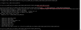
xil_printf("AXI DMA interrupt example test passed/r/n");
/* Disable TX and RX Ring interrupts and return success */
DisableIntrSystem(&Intc, TX_INTR_ID, RX_INTR_ID);
Done:
xil_printf("--- Exiting main() --- /r/n");
return XST_SUCCESS;
}
#ifdef XPAR_UARTNS550_0_BASEADDR
/*****************************************************************************/
/*
*
* Uart16550 setup routine, need to set baudrate to 9600 and data bits to 8
*
* @param None
*
* @return None
*
* @note None.
*
******************************************************************************/
static void Uart550_Setup(void)
{
XUartNs550_SetBaud(XPAR_UARTNS550_0_BASEADDR,
XPAR_XUARTNS550_CLOCK_HZ, 9600);
XUartNs550_SetLineControlReg(XPAR_UARTNS550_0_BASEADDR,
XUN_LCR_8_DATA_BITS);
}
#endif
/*****************************************************************************/
/*
*
* This function checks data buffer after the DMA transfer is finished.
*
* We use the static tx/rx buffers.
*
* @param Length is the length to check
* @param StartValue is the starting value of the first byte
*
* @return
* - XST_SUCCESS if validation is successful
* - XST_FAILURE if validation is failure.
*
* @note None.
*
******************************************************************************/
static int CheckData(int Length, u8 StartValue)
{
u8 *RxPacket;
int Index = 0;
u8 Value;
RxPacket = (u8 *) RX_BUFFER_BASE;
Value = StartValue;
/* Invalidate the DestBuffer before receiving the data, in case the
* Data Cache is enabled
*/
#ifndef __aarch64__
Xil_DCacheInvalidateRange((u32)RxPacket, Length);
#endif
for(Index = 0; Index if (RxPacket[Index] != Value) {
xil_printf("Data error %d: %x/%x/r/n",
Index, RxPacket[Index], Value);
return XST_FAILURE;
}
Value = (Value + 1) & 0xFF;
}
return XST_SUCCESS;
}
/*****************************************************************************/
/*
*
* This is the DMA TX Interrupt handler function.
*
* It gets the interrupt status from the hardware, acknowledges it, and if any
* error happens, it resets the hardware. Otherwise, if a completion interrupt
* is present, then sets the TxDone.flag
*
* @param Callback is a pointer to TX channel of the DMA engine.
*
* @return None.
*
* @note None.
*
******************************************************************************/
static void TxIntrHandler(void *Callback)
{
u32 IrqStatus;
int TimeOut;
XAxiDma *AxiDmaInst = (XAxiDma *)Callback;
/* Read pending interrupts */
IrqStatus = XAxiDma_IntrGetIrq(AxiDmaInst, XAXIDMA_DMA_TO_DEVICE);
/* Acknowledge pending interrupts */
XAxiDma_IntrAckIrq(AxiDmaInst, IrqStatus, XAXIDMA_DMA_TO_DEVICE);
/*
* If no interrupt is asserted, we do not do anything
*/
if (!(IrqStatus & XAXIDMA_IRQ_ALL_MASK)) {
return;
}
/*
* If error interrupt is asserted, raise error flag, reset the
* hardware to recover from the error, and return with no further
* processing.
*/
if ((IrqStatus & XAXIDMA_IRQ_ERROR_MASK)) {
Error = 1;
/*
* Reset should never fail for transmit channel
*/
XAxiDma_Reset(AxiDmaInst);
TimeOut = RESET_TIMEOUT_COUNTER;
while (TimeOut) {
if (XAxiDma_ResetIsDone(AxiDmaInst)) {
break;
}
TimeOut -= 1;
}
return;
}
/*
* If Completion interrupt is asserted, then set the TxDone flag
*/
if ((IrqStatus & XAXIDMA_IRQ_IOC_MASK)) {
TxDone = 1;
}
}
/*****************************************************************************/
/*
*
* This is the DMA RX interrupt handler function
*
* It gets the interrupt status from the hardware, acknowledges it, and if any
* error happens, it resets the hardware. Otherwise, if a completion interrupt
* is present, then it sets the RxDone flag.
*
* @param Callback is a pointer to RX channel of the DMA engine.
*
* @return None.
*
* @note None.
*
******************************************************************************/
static void RxIntrHandler(void *Callback)
{
u32 IrqStatus;
int TimeOut;
XAxiDma *AxiDmaInst = (XAxiDma *)Callback;
/* Read pending interrupts */
IrqStatus = XAxiDma_IntrGetIrq(AxiDmaInst, XAXIDMA_DEVICE_TO_DMA);
/* Acknowledge pending interrupts */
XAxiDma_IntrAckIrq(AxiDmaInst, IrqStatus, XAXIDMA_DEVICE_TO_DMA);
/*
* If no interrupt is asserted, we do not do anything
*/
if (!(IrqStatus & XAXIDMA_IRQ_ALL_MASK)) {
return;
}
/*
* If error interrupt is asserted, raise error flag, reset the
* hardware to recover from the error, and return with no further
* processing.
*/
if ((IrqStatus & XAXIDMA_IRQ_ERROR_MASK)) {
Error = 1;
/* Reset could fail and hang
* NEED a way to handle this or do not call it??
*/
XAxiDma_Reset(AxiDmaInst);
TimeOut = RESET_TIMEOUT_COUNTER;
while (TimeOut) {
if(XAxiDma_ResetIsDone(AxiDmaInst)) {
break;
}
TimeOut -= 1;
}
return;
}
/*
* If completion interrupt is asserted, then set RxDone flag
*/
if ((IrqStatus & XAXIDMA_IRQ_IOC_MASK)) {
RxDone = 1;
}
}
/*****************************************************************************/
/*
*
* This function setups the interrupt system so interrupts can occur for the
* DMA, it assumes INTC component exists in the hardware system.
*
* @param IntcInstancePtr is a pointer to the instance of the INTC.
* @param AxiDmaPtr is a pointer to the instance of the DMA engine
* @param TxIntrId is the TX channel Interrupt ID.
* @param RxIntrId is the RX channel Interrupt ID.
*
* @return
* - XST_SUCCESS if successful,
* - XST_FAILURE.if not succesful
*
* @note None.
*
******************************************************************************/
static int SetupIntrSystem(INTC * IntcInstancePtr,
XAxiDma * AxiDmaPtr, u16 TxIntrId, u16 RxIntrId)
{
int Status;
#ifdef XPAR_INTC_0_DEVICE_ID
/* Initialize the interrupt controller and connect the ISRs */
Status = XIntc_Initialize(IntcInstancePtr, INTC_DEVICE_ID);
if (Status != XST_SUCCESS) {
xil_printf("Failed init intc/r/n");
return XST_FAILURE;
}
Status = XIntc_Connect(IntcInstancePtr, TxIntrId,
(XInterruptHandler) TxIntrHandler, AxiDmaPtr);
if (Status != XST_SUCCESS) {
xil_printf("Failed tx connect intc/r/n");
return XST_FAILURE;
}
Status = XIntc_Connect(IntcInstancePtr, RxIntrId,
(XInterruptHandler) RxIntrHandler, AxiDmaPtr);
if (Status != XST_SUCCESS) {
xil_printf("Failed rx connect intc/r/n");
return XST_FAILURE;
}
/* Start the interrupt controller */
Status = XIntc_Start(IntcInstancePtr, XIN_REAL_MODE);
if (Status != XST_SUCCESS) {
xil_printf("Failed to start intc/r/n");
return XST_FAILURE;
}
XIntc_Enable(IntcInstancePtr, TxIntrId);
XIntc_Enable(IntcInstancePtr, RxIntrId);
#else
XScuGic_Config *IntcConfig;
/*
* Initialize the interrupt controller driver so that it is ready to
* use.
*/
IntcConfig = XScuGic_LookupConfig(INTC_DEVICE_ID);
if (NULL == IntcConfig) {
return XST_FAILURE;
}
Status = XScuGic_CfgInitialize(IntcInstancePtr, IntcConfig,
IntcConfig->CpuBaseAddress);
if (Status != XST_SUCCESS) {
return XST_FAILURE;
}
XScuGic_SetPriorityTriggerType(IntcInstancePtr, TxIntrId, 0xA0, 0x3);
XScuGic_SetPriorityTriggerType(IntcInstancePtr, RxIntrId, 0xA0, 0x3);
/*
* Connect the device driver handler that will be called when an
* interrupt for the device occurs, the handler defined above performs
* the specific interrupt processing for the device.
*/
Status = XScuGic_Connect(IntcInstancePtr, TxIntrId,
(Xil_InterruptHandler)TxIntrHandler,
AxiDmaPtr);
if (Status != XST_SUCCESS) {
return Status;
}
Status = XScuGic_Connect(IntcInstancePtr, RxIntrId,
(Xil_InterruptHandler)RxIntrHandler,
AxiDmaPtr);
if (Status != XST_SUCCESS) {
return Status;
}
XScuGic_Enable(IntcInstancePtr, TxIntrId);
XScuGic_Enable(IntcInstancePtr, RxIntrId);
#endif
/* Enable interrupts from the hardware */
Xil_ExceptionInit();
Xil_ExceptionRegisterHandler(XIL_EXCEPTION_ID_INT,
(Xil_ExceptionHandler)INTC_HANDLER,
(void *)IntcInstancePtr);
Xil_ExceptionEnable();
return XST_SUCCESS;
}
/*****************************************************************************/
/**
*
* This function disables the interrupts for DMA engine.
*
* @param IntcInstancePtr is the pointer to the INTC component instance
* @param TxIntrId is interrupt ID associated w/ DMA TX channel
* @param RxIntrId is interrupt ID associated w/ DMA RX channel
*
* @return None.
*
* @note None.
*
******************************************************************************/
static void DisableIntrSystem(INTC * IntcInstancePtr,
u16 TxIntrId, u16 RxIntrId)
{
#ifdef XPAR_INTC_0_DEVICE_ID
/* Disconnect the interrupts for the DMA TX and RX channels */
XIntc_Disconnect(IntcInstancePtr, TxIntrId);
XIntc_Disconnect(IntcInstancePtr, RxIntrId);
#else
XScuGic_Disconnect(IntcInstancePtr, TxIntrId);
XScuGic_Disconnect(IntcInstancePtr, RxIntrId);
#endif
}
xaxidma_example_simple_intr.c
主函数中依次完成了:DMA初始化,建立中断系统,使能DMA中断,初始化标志位及发送数据,启动DMA传输以及数据检测。中断部分的内容与PS DMA非常相近,传输完成后进入的中断函数中仅置位了发送或接收完成标志位:
static void TxIntrHandler(void *Callback)
{
u32 IrqStatus;
int TimeOut;
XAxiDma *AxiDmaInst = (XAxiDma *)Callback;
/* Read pending interrupts */
IrqStatus = XAxiDma_IntrGetIrq(AxiDmaInst, XAXIDMA_DMA_TO_DEVICE);
/* Acknowledge pending interrupts */
XAxiDma_IntrAckIrq(AxiDmaInst, IrqStatus, XAXIDMA_DMA_TO_DEVICE);
/*
* If no interrupt is asserted, we do not do anything
*/
if (!(IrqStatus & XAXIDMA_IRQ_ALL_MASK)) {
return;
}
/*
* If error interrupt is asserted, raise error flag, reset the
* hardware to recover from the error, and return with no further
* processing.
*/
if ((IrqStatus & XAXIDMA_IRQ_ERROR_MASK)) {
Error = 1;
/*
* Reset should never fail for transmit channel
*/
XAxiDma_Reset(AxiDmaInst);
TimeOut = RESET_TIMEOUT_COUNTER;
while (TimeOut) {
if (XAxiDma_ResetIsDone(AxiDmaInst)) {
break;
}
TimeOut -= 1;
}
return;
}
/*
* If Completion interrupt is asserted, then set the TxDone flag
*/
if ((IrqStatus & XAXIDMA_IRQ_IOC_MASK)) {
TxDone = 1;
}
}
/*****************************************************************************/
/*
*
* This is the DMA RX interrupt handler function
*
* It gets the interrupt status from the hardware, acknowledges it, and if any
* error happens, it resets the hardware. Otherwise, if a completion interrupt
* is present, then it sets the RxDone flag.
*
* @param Callback is a pointer to RX channel of the DMA engine.
*
* @return None.
*
* @note None.
*
******************************************************************************/
static void RxIntrHandler(void *Callback)
{
u32 IrqStatus;
int TimeOut;
XAxiDma *AxiDmaInst = (XAxiDma *)Callback;
/* Read pending interrupts */
IrqStatus = XAxiDma_IntrGetIrq(AxiDmaInst, XAXIDMA_DEVICE_TO_DMA);
/* Acknowledge pending interrupts */
XAxiDma_IntrAckIrq(AxiDmaInst, IrqStatus, XAXIDMA_DEVICE_TO_DMA);
/*
* If no interrupt is asserted, we do not do anything
*/
if (!(IrqStatus & XAXIDMA_IRQ_ALL_MASK)) {
return;
}
/*
* If error interrupt is asserted, raise error flag, reset the
* hardware to recover from the error, and return with no further
* processing.
*/
if ((IrqStatus & XAXIDMA_IRQ_ERROR_MASK)) {
Error = 1;
/* Reset could fail and hang
* NEED a way to handle this or do not call it??
*/
XAxiDma_Reset(AxiDmaInst);
TimeOut = RESET_TIMEOUT_COUNTER;
while (TimeOut) {
if(XAxiDma_ResetIsDone(AxiDmaInst)) {
break;
}
TimeOut -= 1;
}
return;
}
/*
* If completion interrupt is asserted, then set RxDone flag
*/
if ((IrqStatus & XAXIDMA_IRQ_IOC_MASK)) {
RxDone = 1;
}
}
intrHandler
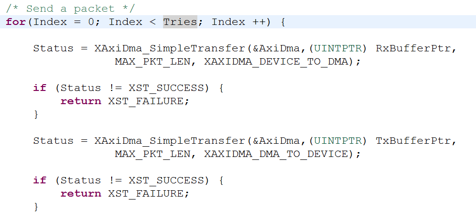
DMA启动传输部分如下,调用库函数XAxiDma_SimpleTransfer。以第一个为例,是将RxBufferPtr为数据首地址,MAX_PKT_LEN为字节数,XAXIDMA_DEVICE_TO_DMA为传输方向启动DMA传输数据。MAX_PKT_LEN不能超过之前IP核配置参数指定的16384byte,XAXIDMA_DEVICE_TO_DMA和XAXIDMA_DMA_TO_DEVICE依次指PL-> DMA ->PS以及PS->DMA -> PL方向,也就是PL就是其中的DEVICE。DMA启动函数只有一个地址,这是与PS端DMA最大的区别,因为数据搬移的另一侧是带有无地址的流接口的IP核,该侧“地址”由硬件连接决定。
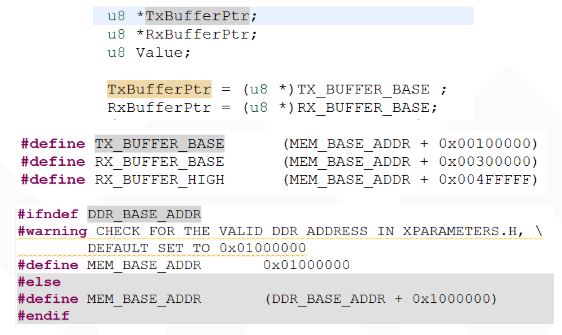
再来看看搬移数据内存首地址RxBufferPtr和TxBufferPtr.从下边的定义可见MEM_BASE_ADDR是DDR_BASE_ADDR加上一段偏移量的结果,DDR基地址数值从xparameters.h中查看。
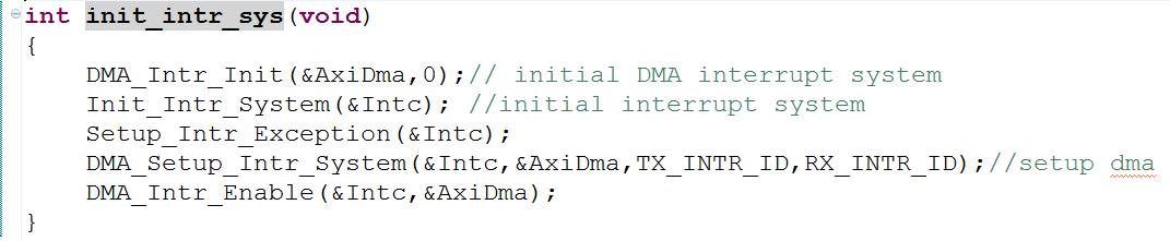
四、函数重用封装
官方的代码比较乱,都写在main函数里,米联客教程init_intr_sys()函数完成整个中断系统的建立,将官方demo中main函数DMA测试之前关于中断部分的代码全部封装其中,包括DMA中断初始化,中断控制器初始化,使能中断异常,连接DMA发送与接收中断,DMA中断使能五个过程。
五、AXI总线信号ILA波形分析
AXI Stream主要接口:
tdata:数据tkeep:字节有效指示tlast:帧尾指示tready:准备就绪tvalid:数据有效指示
MM2S方向一旦tvalid拉高则触发ILA抓取信号波形。一帧数据有64个,每个数据32bit(4byte),一共正好为C代码中MAX_PKT_LEN数值,即256byte。
其中他keep信号比较关键。如当stream位宽为16bit,传输数据量为255byte时,tkeep信号在最后一个stream数据对应位置是2'b01指示第128个16bit数中最后一个数的高字节为upsize过程中无效填充数据。
后续本人会利用System Generator设计算法IP,之后集成到IP Integerator中作为CPU外设进行板级验证。继续学习!
编辑:hfy
-
寄存器
+关注
关注
31文章
5620浏览量
130455 -
cpu
+关注
关注
68文章
11332浏览量
225991 -
数据传输
+关注
关注
9文章
2230浏览量
67750 -
Zynq
+关注
关注
10文章
633浏览量
49589 -
AXI
+关注
关注
1文章
145浏览量
18036
发布评论请先 登录
利用开源uart2axi4实现串口访问axi总线

基于AXI DMA IP核的DDR数据存储与PS端读取
使用AXI4接口IP核进行DDR读写测试
Xilinx高性能NVMe Host控制器IP+PCIe 3.0软核控制器IP,纯逻辑实现,AXI4和AXI4-Stream DMA接口,支持PCIe 3.0和4.0
利用蜂鸟E203搭建SoC【1】——AXI总线的配置与板级验证
人脸识别和AES加密协同的SOC设计架构
利用蜂鸟E203搭建SoC【5】——DMA使用
NVMe高速传输之摆脱XDMA设计42:DMA 读写功能验证与分析
双Zynq MPSoC PS侧PCIe高速DMA互连解决方案
AXI GPIO扩展e203 IO口简介
基于E203的DMA ip的使用
ZYNQ PS与PL数据交互方式
基于DE1-SOC开发板的oneAPI实验教程(2)
AMD Versal Adaptive SoC Clock Wizard AXI DRP示例


评论