 应用于77/79 GHz汽车防撞雷达的高可靠性板材

摘要
基于ADAS (高级驾驶辅助系统)系统中77/79GHz汽车防撞雷达的潜在增长。从电气和可靠性的角度来看,无玻纤的聚四氟乙烯陶瓷板材相较于非聚四氟乙烯的板材具有明显的优势。
聚四氟乙烯(PTFE)的介电常数和损耗因子在传感器谐振频率要求的工作温度范围内表现出高稳定性,几十年来得到了射频和微波行业的广泛认可。
聚四氟乙烯基材上搭配极低粗糙度(ULP,Ultra Low Profile)的电解铜箔,相较于压延铜箔,其插损更低,成本也更有竞争力。
图1:ADAS的应用
ADAS案例
为什么现在我们都对ADAS系统中的77/79GHz汽车防撞雷达产品如此感兴趣呢?尽管前期数量不多,但市场的可接受度正变得越来越高,就像很多年前的ABS系统一样,从开始只有豪华车配置到后来的所有车辆配置,可预见未来几年其将呈指数级增长,因为所有的汽车制造商都希望引入ADAS系统。
图2:77GHz 防撞雷达(博世提供)
图3:77GHz 防撞雷达(博世提供)
材料特性
PCB中使用的射频板材必须在非常宽的温度范围内保持非常稳定的电气性能。PTFE板材显示出非常稳定的DK / DK(@23C)比值,温度由-50到+ 150°C(图4):
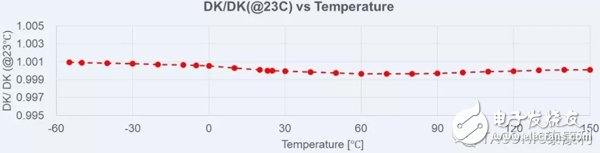
图4:PTFE板材从-50到+150 °C表现出非常稳定的Dk特性
同样的,Df在同样的温度范围内的变化非常平缓(图5):
图5:PTFE板材从-50 到+150 °C的Df
而非聚四氟乙烯(Non-PTFE)树脂有着较高的极性,碳-氧键(C-O)容易被极化,其表现为在高频应用时电气性能不稳定。
NF-30是一款不含玻纤的聚四氟乙烯板材,其在X,Y,Z三个方向上的各向一致性非常好。从电气性能上考量,常规玻璃纤维布的存在会导致板材在各向之间的差异。当然扁平玻璃布会较常规玻璃布有一定改善,但也不能完全消除这个差异。
“极低粗糙度”电解铜箔(ULP)与传统的低粗糙度电解铜箔(VLP)相比(图6),ULP铜箔能够做出更精细的图形和更严的线宽公差。
图6: ULPH铜箔与VLP铜箔的对比(卢森堡铜箔提供)
更重要的是,插损得到了极大的改善,频率越高越明显(图7.):
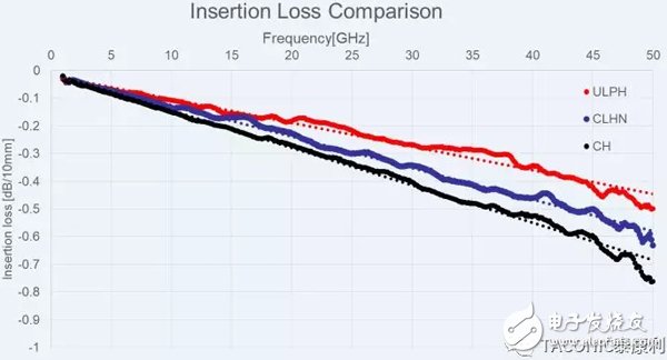
图7:NF-30 Hoz铜箔的极低粗糙度(ULPH),反转铜(CLH)与低粗糙度(CH)的插损对比
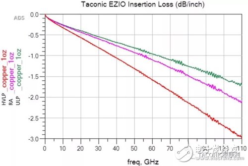
图8:1OZ铜箔的极低粗糙度(ULPH),压延(RA)与低粗糙度(HVLP)搭配相同的介质材料,测试至110GHz的插损对比
1oz的极低粗糙度电解铜(ULP)、压延铜(RA)、低粗糙度电解铜(HVLP)插损的对比。频率测至110GHz时,ULP与RA铜相比,优势越来越大(图8).
此外,PTFE板材的另一个主要优点在于无论采用何种表面处理方式,其铜箔附着力在多次无铅回流后,仍然能够保持较高的水平。ULP剥离强度的测试结果与HVLP几乎一样(图9).
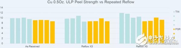
图9:Hoz极低粗糙度(ULPH)的铜箔经过3次与5次IR-Reflow后的剥离强度
DK,插损的测量
再好的理论数据,不如在77GHz测量实际的DK和插损。DK测量采用波导连接器谐振环测试方法测量微带线,而插损测量采用不同长度的微带线。(图10).
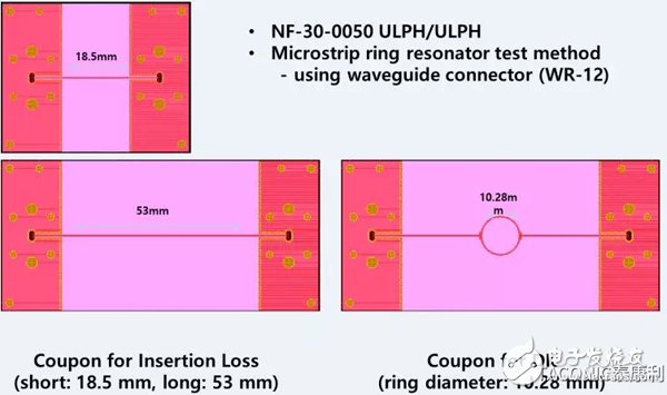
图10:Dk与插损的微带线谐振环测试图形
在77GHz测试频率下,ULP铜箔改善了插损,但是DK比普通铜箔在77GHz时的理论值低了大约0.1 (图11).
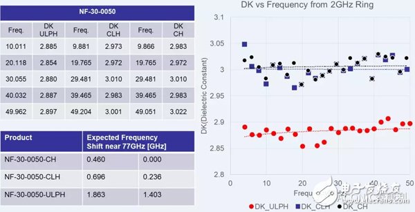
图11:NF-30 Dk随频率的偏移与铜箔类型有关
这种影响是由于这种铜箔的类型导致的,但很容易在仿真软件里进行调整。
谐振环S21在-40°C 和+125°C测量表现了这一点偏移(图12):
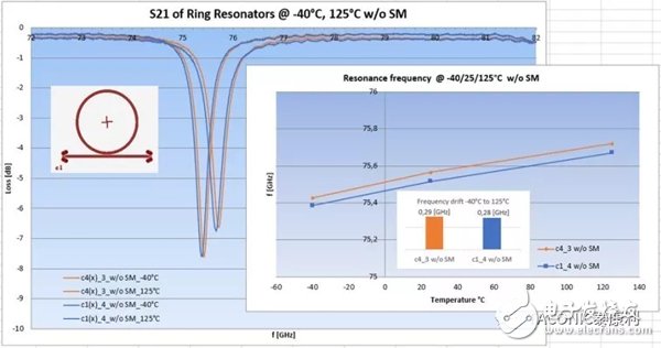
图12:S21谐振环测量的在-40°C和+125°C偏移(博世提供)
同时谐振环在78~80GHz的插入损耗也是可以接受的(图13):
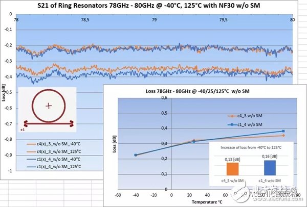
图13:S21谐振环在-40°C 和+125°C测量的插损(博世提供)
大多数的77/79 GHz ADAS 线路板是多层混压板, 只有第1层到第2层是PTFE板材.
PTFE板材的高可靠性在以下的288 °C的漂锡测试中得到验证(图14 a-c):
图14a: NF-30 288°C漂锡前
图14b: NF-30 在做288 °C漂锡
图14c: NF-30 288 °C漂锡30分钟后: 没有起泡,没有爆板!
使用较厚的厚度20和60mil的NF-30来测试钻孔,除孔污和电镀孔,很明显这种无玻纤PTFE板材PTH孔孔壁质量非常高(图15)
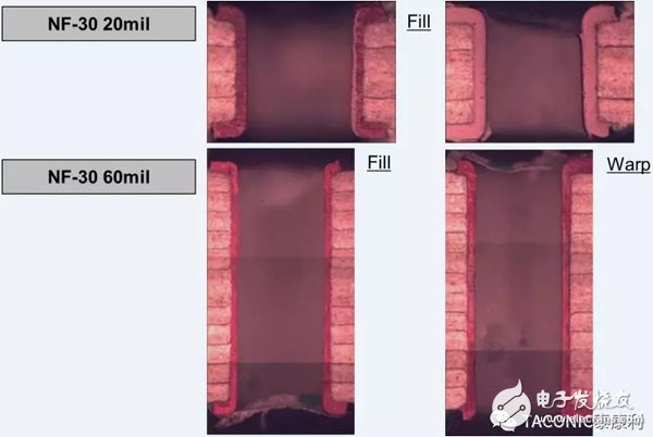
图15: 20mil与60mil NF-30的PTH孔
1000次-40°C到+ 140°C冷热冲击循环是对混压多层板来说是极大的挑战(图16, 17)
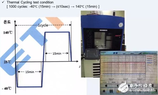
图16: 混压多层板的冷热循环曲线 -40°C到+ 140°C 1,000循环
不管怎样,1000次循环测试后没有任何问题。
图17:NF-30混压多层板切片 –NF-30的多层板及盲孔;热循环前与热循环后
即使经过50次的漂锡试验(288 °C,10S),依然显示出很高的可靠性(图18)
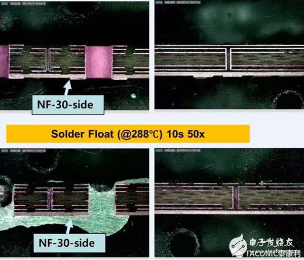
图18:NF-30的混压多层板经过50次漂锡( 288 °C 10秒)
高可靠性和电气性能需要从板材的生产过程到场景应用一直保持着稳定的介电常数。一个众所周知的顾虑就是陶瓷填料板在PCB制作过程中的药水吸附问题。NF-30采用更好的配方来减少最常见的化学药水的渗透问题。 图19显示了NF-30与市场的另一款无玻纤结构PTFE介质材料的耐化学药水吸附测试结果。
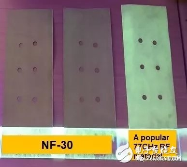
图19:NF-30与其他材料相比,明显减少化学药水的吸收
结论
NF-30 是一款高可靠性射频材料,适用于77/79GHz 汽车防撞雷达的混压多层板, 纯多层板以及双面板的设计。
参考文献
除了一些特定的引用外,其他所有信息都是Taconic内部测试信息。
———————————————————
附英语原文:
FOR 77/79 GHZ SAFETY AND RELIABILITY APPLICATIONS THE MOST RELIABLE LAMINATES ARE USED
Manfred Huschka1
1Taconic Advanced Dielectric Division,Mullingar, Ireland
Keywords: ADAS, PTFE, NON-REINFORCED,COPPER FOIL, INSERTION LOSS
Abstract
Due to the expected potential growth of 77/79 GHz ADAS (Advanced Ariver-Assistance System) several non-PTFE (Polytetra Fluoro Ethylene) laminates are trying to find their way into designs. However from electrical and mechanical reliability points of view non-reinforced PTFE/Ceramic laminates still provide a leading edge.
The high consistency of dielectric constant and loss factor of the thermoplastic material PTFE over the required operating temperature range at resonance frequency of the sensors has been recognized by the RF and microwave industry since tens of years. This is also one of the main reasons why such types of laminates are being used for every ADAS generation up to now.
For many years only one kind of such laminate was available and therefore is widely used in the industry. 2017 saw the emergence of another such type of laminate, whose tested reliability data confirm that the selection of non-reinforced PTFE laminates for 77/79 GHz is the correct one. In fact, certain features demonstrate a second generation laminate is needed in order to meet the requirements of next generation 77/79 GHz ADAS.
The market introduction of almost no profile ED (Electro-Deposited) copper foil provides an even improved insertion loss over rolled annealed copper foil, in addition to its lower cost. Only PTFE laminates result in high enough copper peel strength even at repeated rework cycles.
The Case for ADAS
Why are we now so interested in 77 GHz ADAS? It has been around for some time, although in small volumes. The market acceptance is becoming quite high, and in a similar way as ABS years ago it gets cascaded down from luxury cars to almost every car. Exponential growth rates in the next few years are expected – and will happen, because all the car makers want to introduce ADAS.
Safety and reliability have become key words in the industry.
BaseMaterial Characteristics
The RF laminate used in the printedcircuit board is required to be very stable over a very wide temperature range.PTFE laminates show a very tight DK/DK(@23C) (Dielectric Constant/Loss Factor) behaviourfrom -50 to +150 °C (Fig. 4):
Likewise the gradient of DF over the same temperature range is very low (Fig. 5):
Non-PTFE organic resins are bound to have higher levels of natural electrical polarity - the Carbon-Fluorine bond in PTFE is short and not very polarizable in an electrical field, while Carbon-Oxygen bonds are naturally more polarizable. This means a lesser degree of stability over frequency.
NF-30 is a non-reinforced PTFE laminate, just containing ceramic fillers. Same as the laminate being used for current 77 GHz designs, it is electrically very homogeneous in all 3 directions. A woven fiberglass reinforced resin will naturally have some electrical anisotropy due to the fiberglass weave structure, which in particular high mmWave frequencies are sensitive to. It is possible to flatten the fiberglass however the warp yarns never get flat. There will always be a higher level of anisotropy in these type of resin systems.
Recent developments in copper foil technology have resulted in the introduction of a so-called “Almost No Profile” ED copper foil [Taconic grade name for Hoz is ULPH] (Fig. 6). Compared with a traditional Very Low Profile copper foil this foil leads to better defined and much steeper sidewalls of traces due to less copper treatment which has to get etched out of the substrate; in other words, finer features with tighter tolerances are possible.
And what’s of significance is that the insertion loss gets improved considerably – the higher the frequency the better the insertion loss (Fig 7.):
Insertion Loss Comparison of 1 oz “Almost No Profile” ED copper foil (ULP), Rolled Annealed copper foil (RA), and Flat Profile ED copper foil (HVLP) on a different substrate, measured up to 110 GHz shows that the improvement gap widens even more compared with RA copper foil (Fig. 8).
A major advantage of a thermoplastic substrate, such as PTFE, lies in the high copper foil peel strength even after repeated IR reflows, irrespective whether an organic surface protection (PSR) is used or just immersion tin. Measured peel strength values are in the same range as of standard Very Low Profile copper foil (Fig. 9).
mmWave Measurements
All theory is fine, however the proof isin the pudding when doing actual DK and Insertion Loss tests at 77 GHz.Microstrip ring resonator test method using waveguide connectors is applied forDK measurements, whereas strip lines of different lengths are used forInsertion Loss (Fig. 10).
Although the Almost No Profile copper foil improves the insertion loss, it also leads to a DK shift to a 0.1 lower value for design purposes at 77 GHz (Fig. 11).
This observed effect is due to the actual profile structure of this copper foil, and can easily be incorporated into any design through simulation software.
S21 of ring resonators measured at -40°C and at +125°C show a quite small frequency drift (Fig. 12):
Also the observed loss in the frequency range between 78 and 80 GHz shows an acceptable increase (Fig. 13):
Most 77/79 GHz ADAS pcbs are hybrid multilayer pcbs, where only layers 1 and 2 are PTFE laminate.
Aforementioned high reliability of PTFE laminates can easily get demonstrated during 288 °C solder float (Fig. 14 a-c):
Taking the unusual step of using rather thick 20 and 60 mil NF-30 to demonstrate via drilling, hole wall desmearing and pth, it is obvious that it is of no issue for this no glass containing PTFE laminate (Fig. 15)
The biggest challenge is thermal cycling of the hybrid multilayer - 1,000 cycles from -40°C to + 140°C (Fig. 16, 17)
Howeverthe hybrid multilayer survives this test without any issues:
And even after 50x solder float (10 s at 288 °C) the hybrid multilayer shows its superior quality (Fig.18)
Reliability and electrical performance needs dielectric consistency from laminate production through to field deployment. A known concern with ceramic filled dielectrics is process chemistry absorption during the PCB fabrication steps. Observations in one popular laminate of cosmetic changes, as well as some measured shifts in electrical properties at 77/79GHz. It is much preferred to have finished PCBs with no contamination and NF-30 is constructed to minimize penetration and interaction of most common PCB chemistry. Fig 19 shows tests of machined NF-30 dielectric. This is achieved through care in ceramic filler selection and mixing, leading to better cosmetic results after etching in the PCB production process.
Conclusion
NF-30 is truly a high reliability RF basematerial, suitable for 77/79 GHz ASAS hybrid multilayer printed circuit boards,all-RF multilayer printed circuit boards, as well as double-sided printedcircuit boards. The combination of non-reinforced PTFE laminates with Almost NoProfile copper foil is the ideal solution – providing the supply chain with asafe knowledge of long term reliability in operation.
References
Except wherespecific references were made all other information is Taconic internal test information.
Biography
Dipl.-Ing. Manfred Huschka spent his entire professional career in the printed circuit board industry: After graduation he was manufacturing printed circuit boards (Braun Ireland Ltd). Thereafter manufacturing FR4 base materials (AlliedSignal Laminate Systems), with his final position being Director Technology Europe. Since 1997 Manfred is with Taconic, manufacturing PTFE base materials. In those more than 20 years he was in charge of the Irish manufacturing plant for more than 10 years, and is Vice President Global Sales.
-
PTFE
+关注
关注
0文章
57浏览量
14009 -
adas
+关注
关注
311文章
2361浏览量
212243
发布评论请先 登录
无线通信技术核心定位从 “速度竞赛” 转向超高可靠性
高可靠性导热凝胶极端环境性能 |铬锐特实业

高可靠性电流检测电路设计的关键要点

AWR1642:77/79GHz FMCW雷达传感器的卓越之选
探索AWR1443:77/79GHz FMCW雷达传感器的卓越性能与应用
AWR1243:77 - 79GHz FMCW单芯片收发器的卓越之选
AWR1843:77 - 79GHz单芯片FMCW雷达传感器深度解析
什么是高可靠性?
MGDM-155系列高可靠性DC-DC电源模块
KEMET HRA系列SMD MLCCs:高可靠性电容的理想之选
风华高科ABH10L系列车规电阻:车载电子的高可靠性选择

国巨小尺寸AC0402系列车规电容:汽车级高可靠性解决方案


评论