 使用Ai-M61-32S制作出门提醒设备

一、简介
二、红外感应篇
三、XFS5152CE语音合成篇
四、外壳篇
01
简介
本项目设计初衷是为了提醒自己出门不要忘记带东西——“身”、“手”、“钥”、“钱” (身份证,手机,钥匙,钱包)等。不过现在好像都在线支付了,钱包都不带了。笔者觉得后期可以改造成播报天气等,提醒带伞等等。
项目最初设计是使用安信可24G雷达传感器模块人体微动感应检测模组“Rd-03” 来做。由于手上刚好有一个"HC-SR501 红外感应电子模块传感器" 模块,所以这次先用这个试试。
02
红外感应篇
硬件相关
红外感应模块:HC-SR501
语音合成播报模块:XFS5152
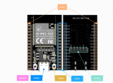
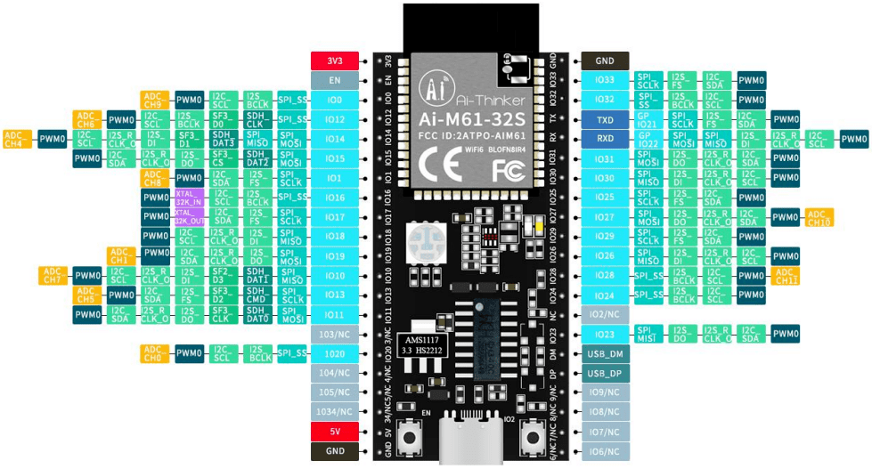
开发板:Ai-M61-32S
GPIO 全称 General Purpose Input Output(通用输入 / 输出),博流系列芯片的 GPIO 外设主要有以下功能。
普通输入输出带上下拉
复用功能带上下拉
模拟功能
外部中断(上升沿、下降沿、高电平、低电平)
硬件消抖
驱动能力控制
GPIO 复用功能通过专门的 pinmux table ,用户只需要修改 table 中的相关引脚的功能,程序会自动配置这些引脚。pinmux table 位于 bsp/board/xxx_board 目录下 pinmux_config.h 文件。
通过标准的 GPIO 设备接口配置引脚,缺点是只能配置普通的输入输出和中断功能,复用功能建议还是使用 table 进行配置。
PIR 传感器如何工作?
**绝对零 (0 开尔文/-273.5 *C) 以上的每个物体都会以红外辐射的形式发出热能。物体越热,它发出的辐射就越多。辐射对人眼是不可见的,PIR传感器专门设计用于检测这种辐射水平。
PIR 传感器由两个主要部分组成,可以看到的热释电传感器是圆形的,中间有一个矩形晶体。
一种称为菲涅尔透镜的特殊透镜,可将红外信号聚焦到热释电传感器上。
热释电传感器热释电传感器由一个窗口和两个由涂层硅制成的矩形槽组成,它允许红外线通过并阻挡任何其他辐射。传感器的设计使得一个可以抵消另一个,这样传感器就可以抵消环境辐射并检测辐射模式的变化。
当没有检测到运动时,产生的输出信号为零,因为传感器正在检测背景辐射。但是,当传感器的任何一半截获运动时,都会导致传感器两部分之间的电压电平发生变化,这就是检测运动的方式。
菲涅耳透镜
菲涅耳透镜由一系列刻在塑料上的同心凹槽组成。这些轮廓充当单独的折射表面,在焦点处聚集平行光线。因此,菲涅耳透镜能够像传统光学透镜一样聚焦光线。
实际上,为了增加 PIR 传感器的范围和视野,透镜被分成几个面部分,每个部分都是一个单独的菲涅尔透镜。
HC-SR501 PIR 运动传感器模块引出线
HC-SR501 模块具有三个引脚。模块丝印被菲涅耳透镜遮挡,请参考下面给出的引脚排列。施加 5V – 12V 电源和接地,传感器输出在检测到运动时变为高电平,在空闲时变为低电平(未检测到运动)。
触发器选择跳线
有两种触发模式决定传感器在检测到运动时如何反应。
单触发模式:持续运动将导致单触发。
多重触发模式:不断的运动会引起一系列的触发。
L - 在此设置中,传感器将处于单触发模式,在此模式下,当检测到运动时输出变高。并在延时电位器设定的一定时间内保持高电平。任何其他类型的检测都会被阻止,直到输出变低。
H - 选择这些设置将设置多重触发模式。在这种模式下,当检测到运动时输出变高,高电平周期由设置的电位器决定。但与单触发模式不同的是,进一步检测不会被阻止并且可以连续触发,当未检测到移动时,引脚变为低电平。
灵敏度调整
PIR 传感器背面有一个电位器,用于调节灵敏度。在电位器的帮助下,可以调整设备的灵敏度。顺时针旋转电位器会增加灵敏度,逆时针旋转电位器会降低灵敏度。
延时调整
传感器背面的另一个锅设置输出将保持高电平的时间以及在检测到运动后顺时针转动锅会增加延迟,逆时针转动锅会减少延迟。
3.3V 稳压器
该模块带有一个 3.3V 稳压器,因此它可以由 4.5V 至 12V 电源供电。虽然 5V 是常用的。
保护二极管
该模块带有一个保护二极管,用于保护二极管免受反向电压和电流的影响。
HC-SR501 PIR 传感器模块故障排除
PIR 传感器无法正常工作可能有多种原因。需要通过一些测试来找出问题的根本原因。
传感器的工作电压为 4.8V 至 20V,因此无法使用 3.3V 为传感器供电。
在某些情况下会看到镜头顶部积聚了灰尘,因此 PIR 传感器可能会停止工作。
如果上述方法均无效,请尝试旋转电位器。如果将电位计的灵敏度设置为最低,那么这可能是传感器不工作的原因。
在测试了所有方法后,如果传感器不工作,那么您可以确定您手中的传感器有故障。
部分代码
#include "bflb\_mtimer.h"
#include "board.h"
#include "bflb\_gpio.h"
#include "locale.h"


#define DBG\_TAG "MAIN"
#include "log.h"


struct bflb\_device\_s *gpio;


int main(void)
{
board\_init();


gpio = bflb\_device\_get\_by\_name("gpio");
bflb\_gpio\_init(gpio, GPIO\_PIN\_13, GPIO\_INPUT | GPIO\_PULLDOWN | GPIO\_SMT\_EN | GPIO\_DRV\_0);
bflb\_gpio\_init(gpio, GPIO\_PIN\_12, GPIO\_OUTPUT | GPIO\_PULLUP | GPIO\_SMT\_EN | GPIO\_DRV\_0);
while (1) {
bool isH = bflb\_gpio\_read(gpio, GPIO\_PIN\_13);
if(isH){
bflb\_gpio\_set(gpio, GPIO\_PIN\_12);
}else{
bflb\_gpio\_reset(gpio, GPIO\_PIN\_12);
}
LOG\_F("是否有人=%d\r\n", isH);
bflb\_mtimer\_delay\_ms(500);
}
}
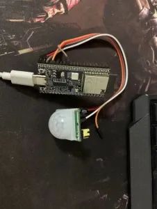
Step1:构建项目并实现 Ai-M61-32S 与 人体红外感应模块 HC-SR501 连接,并获取状态值。
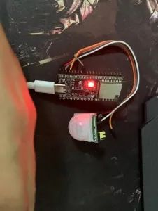
默认灯光是关闭的:
检测有人经过时,红灯亮起。
03
XFS5152CE语音合成篇
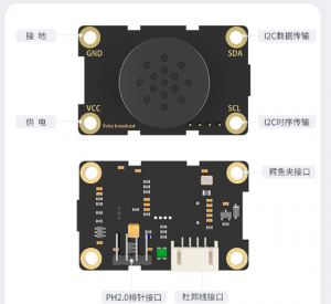
TTS 语音模块:XFS5152CE 语音合成模块
TTS 是 Text To Speech 的缩写,即“从文本到语音”,是人机对话的一部分,让机器能够说话。
语音播报功能的实现方式* TTS 语音模块,比如 XFS5152、SYN6288 等
ISD4000 系列语音录放芯片分段输出
可以按键、UART 控制的 mp3 解码芯片模块
OTP(One Time Programable)语音芯片[定制]
其中 TTS 语音模块使用起来最方便灵活,OTP 语音芯片最简单。
由于项目使用的是 XFS5152CE,所以简单介绍一下科大讯飞的 XFS5152CE 语音合成模块。
性能描述
1 采用 XFS5152CE 语音合成芯片,支持任意中文文本、英文文本合成及中英混读。
2 支持文本控制标记设置,使用便捷,同时提升了文本处理的正确率。
3具有文本智能分析处理功能,对常见的数字、号码、时间、日期、度量衡符号等能正确的识别和处理。
4.具有很强的多音字和中文姓氏处理能力。
5.支持内置多款播音人声可供选择。
6.支持 10 级语速调节。
7.支持 10 级音调调节。
8.支持 10 级音量调节。
9.支持 GB2312、GBK、BIG5 和 UNICODE 四种编码方式。
10.每次合成的文本量多达 4K 字节。
11.集成 80 种常用提示音效,适用于不同场合的信息提示、铃声、警报
等功能。
12.支持多种控制命令,如合成文本、停止合成、状态查询等。
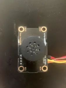
13.板载扬声器。
14.支持三种连接方式:杜邦线接口、鳄鱼夹接口、PH2.0 防呆接口。
15.通信方式:IIC 通信。
16.12C 地址:0x50[新版本 0x30]。
由于协议使用的是 I2C,为了方便使用封装 I2C 功能。
Wire.h
#pragma once


// #include "bouffalo\_sdk.h"
#include "bflb\_gpio.h"
#include "bl616\_gpio.h"
#include "bl616\_glb.h"
#include "bl616\_glb\_gpio.h"
#include "../../drivers/lhal/include/hardware/i2c\_reg.h"
#include "bflb\_i2c.h"
#define lowByte(w) ((uint8\_t) ((w) & 0xff))
#define highByte(w) ((uint8\_t) ((w) >> 8))


bool getWireTimeoutFlag();
bool clearWireTimeoutFlag();
void setWireTimeout(int timeout, bool reset\_on\_timeout);
void onRequest(void (*callback)());
void onReceive(void (*callback)(int));
void setClock(int clockFrequency);
int readI2c();
int available();
int write\_len(uint8_t *str, int len);
int write\_str(uint8_t *str);
int write\_char(unsigned char value);
void endTransmission\_stop(bool stop);
void endTransmission();
void beginTransmission(unsigned char addr);
int requestFrom\_stop(unsigned char addr, int quantity, bool stop);
int requestFrom(unsigned char addr, int quantity);
void end();
void begin\_addr(unsigned char addr);
void begin();
其中
#define lowByte(w) ((uint8_t) ((w) & 0xff))
#define highByte(w) ((uint8_t) ((w) >> 8))
这是 Arduino 中的方法,主要是获取高位和低位数据
Wire.c
#include "Wire.h"


#define PUT_UINT32_LE(field, value)
    do {
        (field)[0] = (uint8_t)((value) >> 0);
        (field)[1] = (uint8_t)((value) >> 8);
        (field)[2] = (uint8_t)((value) >> 16);
        (field)[3] = (uint8_t)((value) >> 24);
    } while (0)


struct bflb_device_s *i2c0;
uint8_t rbuf[128];
int available_count;
int indexi2c;
int wire_timeout;
bool wire_timeout_flag;


void board_i2c_pinmux_init(void)
{
    GLB_GPIO_Type pinlist[] = {
        GLB_GPIO_PIN_30,
        GLB_GPIO_PIN_31
    };
    GLB_GPIO_Func_Init(GPIO_FUN_I2C0, pinlist, 2);
}


bool bflb_i2c_isend(struct bflb_device_s *dev)
{
    uint32_t regval;
    uint32_t reg_base;


    reg_base = dev->reg_base;


    regval = getreg32(reg_base + I2C_INT_STS_OFFSET);


    if (regval & I2C_END_INT) {
        return true;
    }


    return false;
}


bool bflb_i2c_isnak(struct bflb_device_s *dev)
{
    uint32_t regval;
    uint32_t reg_base;


    reg_base = dev->reg_base;


    regval = getreg32(reg_base + I2C_INT_STS_OFFSET);


    if (regval & I2C_NAK_INT) {
        return true;
    }


    return false;
}


bool bflb_i2c_isbusy(struct bflb_device_s *dev)
{
    uint32_t regval;
    uint32_t reg_base;


    reg_base = dev->reg_base;


    regval = getreg32(reg_base + I2C_BUS_BUSY_OFFSET);


    if (regval & I2C_STS_I2C_BUS_BUSY) {
        return true;
    }


    return false;
}


void bflb_i2c_enable(struct bflb_device_s *dev)
{
    uint32_t regval;
    uint32_t reg_base;


    reg_base = dev->reg_base;


    regval = getreg32(reg_base + I2C_CONFIG_OFFSET);
    regval |= I2C_CR_I2C_M_EN;
    putreg32(regval, reg_base + I2C_CONFIG_OFFSET);
}


bool bflb_i2c_isenable(struct bflb_device_s *dev)
{
    uint32_t regval;
    uint32_t reg_base;


    reg_base = dev->reg_base;


    regval = getreg32(reg_base + I2C_CONFIG_OFFSET);
    if (regval & I2C_CR_I2C_M_EN) {
        return true;
    }


    return false;
}


void bflb_i2c_disable(struct bflb_device_s *dev)
{
    uint32_t regval;
    uint32_t reg_base;


    reg_base = dev->reg_base;


    regval = getreg32(reg_base + I2C_CONFIG_OFFSET);
    regval &= ~I2C_CR_I2C_M_EN;
    putreg32(regval, reg_base + I2C_CONFIG_OFFSET);
    /* Clear I2C fifo */
    regval = getreg32(reg_base + I2C_FIFO_CONFIG_0_OFFSET);
    regval |= I2C_TX_FIFO_CLR;
    regval |= I2C_RX_FIFO_CLR;
    putreg32(regval, reg_base + I2C_FIFO_CONFIG_0_OFFSET);
    /* Clear I2C interrupt status */
    regval = getreg32(reg_base + I2C_INT_STS_OFFSET);
    regval |= I2C_CR_I2C_END_CLR;
    regval |= I2C_CR_I2C_NAK_CLR;
    regval |= I2C_CR_I2C_ARB_CLR;
    putreg32(regval, reg_base + I2C_INT_STS_OFFSET);
}


void bflb_i2c_addr_config(struct bflb_device_s *dev, uint16_t slaveaddr, uint16_t subaddr, uint8_t subaddr_size, bool is_addr_10bit)
{
    uint32_t regval;
    uint32_t reg_base;


    reg_base = dev->reg_base;


    regval = getreg32(reg_base + I2C_CONFIG_OFFSET);


    if (subaddr_size > 0) {
        regval |= I2C_CR_I2C_SUB_ADDR_EN;
        regval &= ~I2C_CR_I2C_SUB_ADDR_BC_MASK;
        regval |= ((subaddr_size - 1) << I2C_CR_I2C_SUB_ADDR_BC_SHIFT);
    } else {
        regval &= ~I2C_CR_I2C_SUB_ADDR_EN;
    }


    regval &= ~I2C_CR_I2C_SLV_ADDR_MASK;
    regval |= (slaveaddr << I2C_CR_I2C_SLV_ADDR_SHIFT);
#if !defined(BL602) && !defined(BL702)
    if (is_addr_10bit) {
        regval |= I2C_CR_I2C_10B_ADDR_EN;
    } else {
        regval &= ~I2C_CR_I2C_10B_ADDR_EN;
    }
#endif
    putreg32(subaddr, reg_base + I2C_SUB_ADDR_OFFSET);
    putreg32(regval, reg_base + I2C_CONFIG_OFFSET);
}


void bflb_i2c_set_datalen(struct bflb_device_s *dev, uint16_t data_len)
{
    uint32_t regval;
    uint32_t reg_base;


    reg_base = dev->reg_base;


    regval = getreg32(reg_base + I2C_CONFIG_OFFSET);
    regval &= ~I2C_CR_I2C_PKT_LEN_MASK;
    regval |= ((data_len - 1) << I2C_CR_I2C_PKT_LEN_SHIFT) & I2C_CR_I2C_PKT_LEN_MASK;
    putreg32(regval, reg_base + I2C_CONFIG_OFFSET);
}


void bflb_i2c_set_dir(struct bflb_device_s *dev, bool is_in)
{
    uint32_t regval;
    uint32_t reg_base;


    reg_base = dev->reg_base;


    regval = getreg32(reg_base + I2C_CONFIG_OFFSET);


    if (is_in) {
        regval |= I2C_CR_I2C_PKT_DIR;
    } else {
        regval &= ~I2C_CR_I2C_PKT_DIR;
    }
    putreg32(regval, reg_base + I2C_CONFIG_OFFSET);
}


int bflb_i2c_write_bytes(struct bflb_device_s *dev, uint8_t *data, uint32_t len, uint32_t timeout)
{
    uint32_t reg_base;
    uint32_t temp = 0;
    uint8_t *tmp_buf;
    uint64_t start_time;


    reg_base = dev->reg_base;
    tmp_buf = data;
    while (len >= 4) {
        for (uint8_t i = 0; i < 4; i++) {
            temp += (tmp_buf[i] << ((i % 4) * 8));
        }
        tmp_buf += 4;
        len -= 4;
        start_time = bflb_mtimer_get_time_ms();
        while ((getreg32(reg_base + I2C_FIFO_CONFIG_1_OFFSET) & I2C_TX_FIFO_CNT_MASK) == 0) {
            if ((bflb_mtimer_get_time_ms() - start_time) > timeout) {
                return -ETIMEDOUT;
            }
        }
        putreg32(temp, reg_base + I2C_FIFO_WDATA_OFFSET);
        if (!bflb_i2c_isenable(dev)) {
            bflb_i2c_enable(dev);
        }
        temp = 0;
    }


    if (len > 0) {
        for (uint8_t i = 0; i < len; i++) {
            temp += (tmp_buf[i] << ((i % 4) * 8));
        }
        start_time = bflb_mtimer_get_time_ms();
        while ((getreg32(reg_base + I2C_FIFO_CONFIG_1_OFFSET) & I2C_TX_FIFO_CNT_MASK) == 0) {
            if ((bflb_mtimer_get_time_ms() - start_time) > timeout) {
                return -ETIMEDOUT;
            }
        }
        putreg32(temp, reg_base + I2C_FIFO_WDATA_OFFSET);
        if (!bflb_i2c_isenable(dev)) {
            bflb_i2c_enable(dev);
        }
    }


    start_time = bflb_mtimer_get_time_ms();
    while (bflb_i2c_isbusy(dev) || !bflb_i2c_isend(dev) || bflb_i2c_isnak(dev)) {
        if ((bflb_mtimer_get_time_ms() - start_time) > timeout) {
            return -ETIMEDOUT;
        }
    }
    bflb_i2c_disable(dev);


    return 0;
}


int bflb_i2c_read_bytes(struct bflb_device_s *dev, uint8_t *data, uint32_t len, uint32_t timeout)
{
    uint32_t reg_base;
    uint32_t temp = 0;
    uint8_t *tmp_buf;
    uint64_t start_time;


    reg_base = dev->reg_base;
    tmp_buf = data;


    bflb_i2c_enable(dev);


    while (len >= 4) {
        start_time = bflb_mtimer_get_time_ms();
        while ((getreg32(reg_base + I2C_FIFO_CONFIG_1_OFFSET) & I2C_RX_FIFO_CNT_MASK) == 0) {
            if ((bflb_mtimer_get_time_ms() - start_time) > timeout) {
                return -ETIMEDOUT;
            }
        }
        temp = getreg32(reg_base + I2C_FIFO_RDATA_OFFSET);
        PUT_UINT32_LE(tmp_buf, temp);
        tmp_buf += 4;
        len -= 4;
    }


    if (len > 0) {
        start_time = bflb_mtimer_get_time_ms();
        while ((getreg32(reg_base + I2C_FIFO_CONFIG_1_OFFSET) & I2C_RX_FIFO_CNT_MASK) == 0) {
            if ((bflb_mtimer_get_time_ms() - start_time) > timeout) {
                return -ETIMEDOUT;
            }
        }
        temp = getreg32(reg_base + I2C_FIFO_RDATA_OFFSET);


        for (uint8_t i = 0; i < len; i++) {
            tmp_buf[i] = (temp >> (i * 8)) & 0xff;
        }
    }


    start_time = bflb_mtimer_get_time_ms();
    while (bflb_i2c_isbusy(dev) || !bflb_i2c_isend(dev)) {
        if ((bflb_mtimer_get_time_ms() - start_time) > timeout) {
            return -ETIMEDOUT;
        }
    }
    bflb_i2c_disable(dev);


    return 0;
}


/*
 * address: the 7-bit slave address (optional); if not specified, join the bus as a controller device.
 */
void begin_addr(unsigned char addr) {
    wire_timeout = 100;
    wire_timeout_flag = false;
    board_i2c_pinmux_init();
    i2c0 = bflb_device_get_by_name("i2c0");
    bflb_i2c_init(i2c0, 50000);
}


void begin() {
    wire_timeout = 100;
    wire_timeout_flag = false;
    board_i2c_pinmux_init();
    i2c0 = bflb_device_get_by_name("i2c0");
    bflb_i2c_init(i2c0, 50000);
}


void end() {
    bflb_i2c_deinit(i2c0);
}
/*
 * address: the 7-bit slave address of the device to request bytes from.
 *
 * quantity: the number of bytes to request.
 *
 * stop: true or false. true will send a stop message after the request, releasing the bus.
 * False will continually send a restart after the request, keeping the connection active.
 */


int requestFrom_stop(unsigned char addr, int quantity, bool stop) {
    indexi2c = 0;
    bflb_i2c_disable(i2c0);
    bflb_i2c_enable(i2c0);
    bflb_i2c_addr_config(i2c0, addr, 0, 0, false);
    bflb_i2c_set_datalen(i2c0,quantity);
    bflb_i2c_set_dir(i2c0, 1);
    bflb_i2c_read_bytes(i2c0, rbuf,quantity,wire_timeout);
    available_count = quantity;
    if(true == stop){
        bflb_i2c_disable(i2c0);
    }
    return 0;
}


int requestFrom(unsigned char addr, int quantity) {
    indexi2c = 0;
    bflb_i2c_disable(i2c0);
    bflb_i2c_enable(i2c0);
    bflb_i2c_addr_config(i2c0, addr, 0, 0, false);
    bflb_i2c_set_datalen(i2c0,quantity);
    bflb_i2c_set_dir(i2c0, 1);
    bflb_i2c_read_bytes(i2c0, rbuf,quantity,wire_timeout);
    available_count = quantity;
    return 0;
}


/*
 * address: the 7-bit address of the device to transmit to.
 */
void beginTransmission(unsigned char addr) {
    //bflb_i2c_enable(i2c0);
    bflb_i2c_addr_config(i2c0, addr, 0, 0, false);
    bflb_i2c_set_dir(i2c0, 0);
}


/*
 * stop: true or false. True will send a stop message, releasing the bus after transmission.
 * False will send a restart, keeping the connection active.
 *
 * Returns
 * 0: success.
 * 1: data too long to fit in transmit buffer.
 * 2: received NACK on transmit of address.
 * 3: received NACK on transmit of data.
 * 4: other error.
 * 5: timeout
 */


void endTransmission_stop(bool stop) {
    bflb_i2c_disable(i2c0);
}


void endTransmission() {
    bflb_i2c_disable(i2c0);


}


/*
 * Description
 * This function writes data from a peripheral device in response to a request from
 * a controller device, or queues bytes for transmission from a controller to
 * peripheral device (in-between calls to beginTransmission() and endTransmission()).
 * Syntax
 * Wire.write(value) Wire.write(string) Wire.write(data, length)
 * Parameters
 * value: a value to send as a single byte.
 * string: a string to send as a series of bytes.
 * data: an array of data to send as bytes.
 * length: the number of bytes to transmit.
 * Returns
 * The number of bytes written (reading this number is optional).
 */
int write_char(unsigned char value) {
    bflb_i2c_set_datalen(i2c0, 1);
    bflb_i2c_write_bytes(i2c0, &value, 1,wire_timeout);
  return 0;
}
int write_str(uint8_t *str) {
    bflb_i2c_set_datalen(i2c0, strlen((const char*)str));
    bflb_i2c_write_bytes(i2c0, str, strlen((const char*)str),wire_timeout);
  return 0;
}
int write_len(uint8_t *str, int len) {
    bflb_i2c_set_datalen(i2c0, len);
    int ret = bflb_i2c_write_bytes(i2c0, str, len,wire_timeout);
  return ret;
}


/*
 * Description
 * This function returns the number of bytes available for retrieval with read().
 * This function should be called on a controller device after a call to
 * requestFrom() or on a peripheral inside the onReceive() handler.
 * available() inherits from the Stream utility class.
 */


int available() {
    return available_count;
}


/*
 * Description
 * This function reads a byte that was transmitted from a peripheral device to
 * a controller device after a call to requestFrom() or was transmitted from a
 * controller device to a peripheral device. read() inherits from the Stream utility class.
 * Syntax
 * Wire.read()
 * Parameters
 * None.
 * Returns
 * The next byte received.
 */


int readI2c() {
    unsigned char ret;
    if(available_count){
        available_count--;
        ret = rbuf[indexi2c];
        indexi2c++;
        return ret;
    }
    return 0;
}


/*
 * Description
 * This function modifies the clock frequency for I2C communication.
 * I2C peripheral devices have no minimum working clock frequency,
 * however 100KHz is usually the baseline.
 * Syntax
 * Wire.setClock(clockFrequency)
 * Parameters
 * clockFrequency: the value (in Hertz) of the desired communication clock.
 * Accepted values are 100000 (standard mode) and 400000 (fast mode).
 * Some processors also support 10000 (low speed mode), 1000000 (fast mode plus)
 * and 3400000 (high speed mode). Please refer to the specific processor documentation
 * to make sure the desired mode is supported.
 * Returns
 * None.
 */
void setClock(int clockFrequency) {
    bflb_i2c_deinit(i2c0);
    bflb_i2c_init(i2c0, clockFrequency);
}


/*
 * Description
 * This function registers a function to be called when a peripheral device receives
 * a transmission from a controller device.
 * Syntax
 * Wire.onReceive(handler)
 * Parameters
 * handler: the function to be called when the peripheral device receives data;
 * this should take a single int parameter (the number of bytes read from the controller
 * device) and return nothing.
 * Returns
 * None.
 */
void onReceive(void (*callback)(int)) {
    //we not support slave mode yet
}


/*
 * Description
 * This function registers a function to be called when a controller device requests data from a peripheral device.
 * Syntax
 * Wire.onRequest(handler)
 * Parameters
 * handler: the function to be called, takes no parameters and returns nothing.
 * Returns
 * None.
 */
void onRequest(void (*callback)()) {
    //we not support slave mode yet
}


/*
 * Description
 * Sets the timeout for Wire transmissions in master mode.
 * Syntax
 * Wire.setWireTimeout(timeout, reset_on_timeout)
 * Wire.setWireTimeout()
 * Parameters
 * timeout a timeout: timeout in microseconds, if zero then timeout checking is disabled
 * reset_on_timeout: if true then Wire hardware will be automatically reset on timeout
 * When this function is called without parameters, a default timeout is configured that
 * should be sufficient to prevent lockups in a typical single-master configuration.
 * Returns
 * None.
 */
void setWireTimeout(int timeout, bool reset_on_timeout) {
    wire_timeout = timeout;
    wire_timeout_flag = true;
}


/* Description
 * Clears the timeout flag.
 * Timeouts might not be enabled by default. See the documentation for Wire.setWireTimeout()
 * for more information on how to configure timeouts and how they work.
 * Syntax
 * Wire.clearTimeout()
 * Parameters
 * None.
 * Returns
 * bool: The current value of the flag
 */
bool clearWireTimeoutFlag() {
    wire_timeout_flag = false;
  return true;
}


/*
 * Description
 * Checks whether a timeout has occured since the last time the flag was cleared.
 * This flag is set is set whenever a timeout occurs and cleared when Wire.clearWireTimeoutFlag()
 * is called, or when the timeout is changed using Wire.setWireTimeout().
 * Syntax
 * Wire.getWireTimeoutFlag()
 * Parameters
 * None.
 * Returns
 * bool: The current value of the flag
 */


bool getWireTimeoutFlag() {
  return wire_timeout_flag;
}
这里修改了 I2C 引脚
GLB_GPIO_Type pinlist[] = {
GLB_GPIO_PIN_30,
GLB_GPIO_PIN_31
};
默认是 GLB_GPIO_PIN_14、GLB_GPIO_PIN_15.然后封装.
XFS5152CE 模块功能代码
XFS.h
#ifndef __XFS_H #define __XFS_H #include#include #include #include #include #include #include //Added for uint_t #include #include "bflb_mtimer.h" struct XFS_Protocol_TypeDef { uint8_t DataHead; uint8_t Length_HH; uint8_t Length_LL; uint8_t Commond; uint8_t EncodingFormat; const char* Text; }; /* *| 帧头(1Byte)| 数据区长度(2Byte)| 数据区(<4KByte) | *| | 高字节 | 低字节 | 命令字 | 文本编码格式 | 待合成文本 | *| 0xFD | 0xHH | 0xLL | 0x01 | 0x00~0x03 | ... ... | */ typedef enum { CMD_StartSynthesis = 0x01,//语音合成命令 CMD_StopSynthesis = 0x02,//停止合成命令,没有参数 CMD_PauseSynthesis = 0x03,//暂停合成命令,没有参数 CMD_RecoverySynthesis = 0x04,//恢复合成命令,没有参数 CMD_CheckChipStatus = 0x21,//芯片状态查询命令 CMD_PowerSavingMode = 0x88,//芯片进入省电模式 CMD_NormalMode = 0xFF//芯片从省电模式返回正常工作模式 } CMD_Type;//命令字 void StartSynthesis(const char* str);//开始合成 // void StartSynthesis(String str);//开始合成 bool IIC_WriteByte(uint8_t data); void IIC_WriteByteSize(uint8_t* buff, uint32_t size); void SendCommond(CMD_Type cmd); void StopSynthesis();//停止合成 void PauseSynthesis();//暂停合成 void RecoverySynthesis();//恢复合成 typedef enum { GB2312 = 0x00, GBK = 0x01, BIG5 = 0x02, UNICODE = 0x03 } EncodingFormat_Type;//文本的编码格式 void SetEncodingFormat(EncodingFormat_Type encodingFormat); typedef enum { ChipStatus_InitSuccessful = 0x4A,//初始化成功回传 ChipStatus_CorrectCommand = 0x41,//收到正确的命令帧回传 ChipStatus_ErrorCommand = 0x45,//收到不能识别命令帧回传 ChipStatus_Busy = 0x4E,//芯片忙碌状态回传 ChipStatus_Idle = 0x4F//芯片空闲状态回传 } ChipStatus_Type;//芯片回传 typedef enum { Style_Single,//?为 0,一字一顿的风格 Style_Continue//?为 1,正常合成 } Style_Type; //合成风格设置 [f?] void SetStyle(Style_Type style); typedef enum { Language_Auto,//? 为 0,自动判断语种 Language_Chinese,//? 为 1,阿拉伯数字、度量单位、特殊符号等合成为中文 Language_English//? 为 2,阿拉伯数字、度量单位、特殊符号等合成为英文 } Language_Type; //合成语种设置 [g?] void SetLanguage(Language_Type language); typedef enum { Articulation_Auto,//? 为 0,自动判断单词发音方式 Articulation_Letter,//? 为 1,字母发音方式 Articulation_Word//? 为 2,单词发音方式 } Articulation_Type; //设置单词的发音方式 [h?] void SetArticulation(Articulation_Type articulation); typedef enum { Spell_Disable,//? 为 0,不识别汉语拼音 Spell_Enable//? 为 1,将“拼音+1 位数字(声调)”识别为汉语拼音,例如:hao3 } Spell_Type; //设置对汉语拼音的识别 [i?] void SetSpell(Spell_Type spell); typedef enum { Reader_XiaoYan = 3,//? 为 3,设置发音人为小燕(女声, 推荐发音人) Reader_XuJiu = 51,//? 为 51,设置发音人为许久(男声, 推荐发音人) Reader_XuDuo = 52,//? 为 52,设置发音人为许多(男声) Reader_XiaoPing = 53,//? 为 53,设置发音人为小萍(女声) Reader_DonaldDuck = 54,//? 为 54,设置发音人为唐老鸭(效果器) Reader_XuXiaoBao = 55//? 为 55,设置发音人为许小宝(女童声) } Reader_Type;//选择发音人 [m?] void SetReader(Reader_Type reader); typedef enum { NumberHandle_Auto,//? 为 0,自动判断 NumberHandle_Number,//? 为 1,数字作号码处理 NumberHandle_Value//? 为 2,数字作数值处理 } NumberHandle_Type; //设置数字处理策略 [n?] void SetNumberHandle(NumberHandle_Type numberHandle); typedef enum { ZeroPronunciation_Zero,//? 为 0,读成“zero ZeroPronunciation_O//? 为 1,读成“欧”音 } ZeroPronunciation_Type; //数字“0”在读 作英文、号码时 的读法 [o?] void SetZeroPronunciation(ZeroPronunciation_Type zeroPronunciation); typedef enum { NamePronunciation_Auto,//? 为 0,自动判断姓氏读音 NamePronunciation_Constraint//? 为 1,强制使用姓氏读音规则 } NamePronunciation_Type; //设置姓名读音 策略 [r?] void SetNamePronunciation(NamePronunciation_Type namePronunciation); void SetSpeed(int speed);//设置语速 [s?] ? 为语速值,取值:0~10 void SetIntonation(int intonation);//设置语调 [t?] ? 为语调值,取值:0~10 void SetVolume(int volume);//设置音量 [v?] ? 为音量值,取值:0~10 typedef enum { PromptTone_Disable,//? 为 0,不使用提示音 PromptTone_Enable//? 为 1,使用提示音 } PromptTone_Type; //设置提示音处理策略 [x?] void SetPromptTone(PromptTone_Type promptTone); typedef enum { OnePronunciation_Yao,//? 为 0,合成号码“1”时读成“幺 OnePronunciation_Yi//? 为 1,合成号码“1”时读成“一” } OnePronunciation_Type; //设置号码中“1”的读法 [y?] void SetOnePronunciation(OnePronunciation_Type onePronunciation); typedef enum { Rhythm_Diasble,//? 为 0,“ *”和“#”读出符号 Rhythm_Enable//? 为 1,处理成韵律,“*”用于断词,“#”用于停顿 } Rhythm_Type; //是否使用韵律 标记“*”和“#” [z?] void SetRhythm(Rhythm_Type rhythm); void SetRestoreDefault();//恢复默认的合成参数 [d] 所有设置(除发音人设置、语种设置外)恢复为默认值 void XFS5152CE(uint8_t encodingFormat); void Begin(uint8_t addr); uint8_t GetChipStatus(); void TextCtrl(char c, int d); #endif
XFS.c
#include "XFS.h" #include#define DBG_TAG "MAIN" #include "log.h" #define XFS_DataHead (uint8_t)0xFD uint8_t I2C_Addr; uint8_t ChipStatus; struct XFS_Protocol_TypeDef DataPack; size_t foo( const char* restrict src, uint8_t* restrict dst, size_t dst_maxlen ) { size_t idx = 0; for( ; src[idx] && dst_maxlen; ++idx ) { if( idx%8 == 0 ) *dst = 0; if( src[idx] != '0' ) *dst |= 1<<(7-idx%8); if( idx%8 == 7 ) ++dst, --dst_maxlen; } return (idx+7)/8; } void XFS5152CE(uint8_t encodingFormat) { DataPack.DataHead = XFS_DataHead; DataPack.Length_HH = 0x00; DataPack.Length_LL = 0x00; DataPack.Commond = 0x00; DataPack.EncodingFormat = encodingFormat; ChipStatus = 0x00; } void Begin(uint8_t addr) { I2C_Addr = addr; XFS5152CE(GB2312); begin(); } uint8_t GetChipStatus() { uint8_t AskState[4] = {0xFD,0x00,0x01,0x21}; beginTransmission(I2C_Addr); write_len(AskState,4); endTransmission(); bflb_mtimer_delay_ms(100); requestFrom(I2C_Addr, 1); while (available()) { ChipStatus = readI2c(); } LOG_F("ChipStatus=%x ", ChipStatus); return ChipStatus; } bool IIC_WriteByte(uint8_t data) { beginTransmission(I2C_Addr); write_char(data); endTransmission(); // if(endTransmission()!=0) //发送结束信号 // { // bflb_mtimer_delay_ms(10); // return false; // } bflb_mtimer_delay_ms(10); return true; } void IIC_WriteBytes(uint8_t* buff, uint32_t size) { for (uint32_t i = 0; i < size; i++) { IIC_WriteByte(buff[i]); } } void StartSynthesis(const char* str) { uint16_t size = strlen(str) + 2; DataPack.Length_HH = highByte(size); DataPack.Length_LL = lowByte(size); DataPack.Commond = CMD_StartSynthesis; DataPack.Text = str; uint8_t dst[(strlen(DataPack.Text)-1+7)/8]; size_t len = foo(DataPack.Text, dst, sizeof(dst)/sizeof(*dst) ); IIC_WriteBytes((uint8_t*)&DataPack,5); IIC_WriteBytes(DataPack.Text, strlen(str)); } // void StartSynthesis(String str) // { // StartSynthesis((const char*)str.c_str()); // } void SendCommond(CMD_Type cmd) { DataPack.Length_HH = 0x00; DataPack.Length_LL = 0x01; DataPack.Commond = cmd; beginTransmission(I2C_Addr); write_len((uint8_t*)&DataPack, 4); endTransmission(); } void StopSynthesis() { SendCommond(CMD_StopSynthesis); } void PauseSynthesis() { SendCommond(CMD_PauseSynthesis); } void RecoverySynthesis() { SendCommond(CMD_RecoverySynthesis); } void TextCtrl(char c, int d) { char str[10]; if (d != -1) sprintf(str, "[%c%d]", c, d); else sprintf(str, "[%c]", c); StartSynthesis(str); } void SetEncodingFormat(EncodingFormat_Type encodingFormat) { DataPack.EncodingFormat = encodingFormat; } void SetStyle(Style_Type style) { TextCtrl('f', style); while(GetChipStatus() != ChipStatus_Idle) { bflb_mtimer_delay_ms(30); } } void SetLanguage(Language_Type language) { TextCtrl('g', language); while(GetChipStatus() != ChipStatus_Idle) { bflb_mtimer_delay_ms(30); } } void SetArticulation(Articulation_Type articulation) { TextCtrl('h', articulation); while(GetChipStatus() != ChipStatus_Idle) { bflb_mtimer_delay_ms(30); } } void SetSpell(Spell_Type spell) { TextCtrl('i', spell); while(GetChipStatus() != ChipStatus_Idle) { bflb_mtimer_delay_ms(30); } } void SetReader(Reader_Type reader) { TextCtrl('m', reader); while(GetChipStatus() != ChipStatus_Idle) { bflb_mtimer_delay_ms(30); } } void SetNumberHandle(NumberHandle_Type numberHandle) { TextCtrl('n', numberHandle); while(GetChipStatus() != ChipStatus_Idle) { bflb_mtimer_delay_ms(30); } } void SetZeroPronunciation(ZeroPronunciation_Type zeroPronunciation) { TextCtrl('o', zeroPronunciation); while(GetChipStatus() != ChipStatus_Idle) { bflb_mtimer_delay_ms(30); } } void SetNamePronunciation(NamePronunciation_Type namePronunciation) { TextCtrl('r', namePronunciation); while(GetChipStatus() != ChipStatus_Idle) { bflb_mtimer_delay_ms(30); } } void SetSpeed(int speed) { // speed = constrain(speed, 0, 10); TextCtrl('s', speed); while(GetChipStatus() != ChipStatus_Idle) { bflb_mtimer_delay_ms(30); } } void SetIntonation(int intonation) { // intonation = constrain(intonation, 0, 10); TextCtrl('t', intonation); while(GetChipStatus() != ChipStatus_Idle) { bflb_mtimer_delay_ms(30); } } void SetVolume(int volume) { // volume = constrain(volume, 0, 10); TextCtrl('v', volume); while(GetChipStatus() != ChipStatus_Idle) { bflb_mtimer_delay_ms(30); } } void SetPromptTone(PromptTone_Type promptTone) { TextCtrl('x', promptTone); while(GetChipStatus() != ChipStatus_Idle) { bflb_mtimer_delay_ms(30); } } void SetOnePronunciation(OnePronunciation_Type onePronunciation) { TextCtrl('y', onePronunciation); while(GetChipStatus() != ChipStatus_Idle) { bflb_mtimer_delay_ms(30); } } void SetRhythm(Rhythm_Type rhythm) { TextCtrl('z', rhythm); while(GetChipStatus() != ChipStatus_Idle) { bflb_mtimer_delay_ms(30); } } void SetRestoreDefault() { TextCtrl('d', -1); while(GetChipStatus() != ChipStatus_Idle) { bflb_mtimer_delay_ms(30); } }
语音播报内容 文件头 speak.h,该文件是为了方式播报内容乱码错乱。文件需要保存为 ANSI
char* hello[] = {"主人", "出门记得带手机和钥匙"};
主程序代码 :main.c
#include "bflb_mtimer.h"
#include "board.h"
#include "bflb_gpio.h"
#include "Wire.h"
#include "XFS.h"
#include "speak.h"
#define DBG_TAG "MAIN"
#include "log.h"


/*超时设置,示例为30S*/
static uint32_t LastSpeakTime = 0;
#define SpeakTimeOut 10000


/**
    @brief  初始化语音合成
    @param  无
    @retval 无
*/


uint8_t n = 1;
static void XFS_Init()
{
    Begin(0x30);//设备i2c地址,地址为0x50
    bflb_mtimer_delay_ms(n);
    SetReader(Reader_XuXiaoBao);        //设置发音人
    bflb_mtimer_delay_ms(n);
    SetEncodingFormat(GB2312);           //文本的编码格式
    bflb_mtimer_delay_ms(n);
    SetLanguage(Language_Auto);                 //语种判断
    bflb_mtimer_delay_ms(n);
    SetStyle(Style_Continue);            //合成风格设置
    bflb_mtimer_delay_ms(n);
    SetArticulation(Articulation_Letter);  //设置单词的发音方式
    bflb_mtimer_delay_ms(n);
    SetSpeed(6);                         //设置语速1~10
    bflb_mtimer_delay_ms(n);
    SetIntonation(5);                    //设置语调1~10
    bflb_mtimer_delay_ms(n);
    SetVolume(10);                        //设置音量1~10
    bflb_mtimer_delay_ms(n);
}


unsigned char result = 0xFF;


struct bflb_device_s *gpio;


void gpio_isr() {
    bool isH = bflb_gpio_read(gpio, GPIO_PIN_13);
    if(isH){
        bflb_gpio_set(gpio, GPIO_PIN_12);
        if(GetChipStatus() == ChipStatus_Idle){
            StartSynthesis(hello[1]);
        }
        bflb_mtimer_delay_ms(3000);
    }else{
        bflb_gpio_reset(gpio, GPIO_PIN_12);
    }
}


int main(void)
{
    board_init();


    gpio = bflb_device_get_by_name("gpio");


    bflb_gpio_init(gpio, GPIO_PIN_12, GPIO_OUTPUT | GPIO_PULLUP | GPIO_SMT_EN | GPIO_DRV_0);


    bflb_gpio_int_init(gpio, GPIO_PIN_13, GPIO_INT_TRIG_MODE_SYNC_LOW_LEVEL);
    bflb_gpio_int_mask(gpio, GPIO_PIN_0, false);
    bflb_irq_attach(gpio->irq_num, gpio_isr, gpio);
    bflb_irq_enable(gpio->irq_num);

    XFS_Init();
    StartSynthesis(hello[0]);
    while(GetChipStatus() != ChipStatus_Idle)
    {
        bflb_mtimer_delay_ms(30);
    }


    // SetReader(Reader_XuJiu);        //设置发音人;
    StartSynthesis(hello[1]);
    while(GetChipStatus() != ChipStatus_Idle)
    {
        bflb_mtimer_delay_ms(30);
    }

    while (1) {
        bflb_mtimer_delay_ms(500);
    }
}
修改 CMakeLists.txt
cmake_minimum_required(VERSION 3.15)


include(proj.conf)


find_package(bouffalo_sdk REQUIRED HINTS $ENV{BL_SDK_BASE})
# User
sdk_add_compile_definitions(-DCONFIG_CLI_CMD_ENABLE)
#sdk_add_compile_definitions(-DBL616_DHCP_DEBUG)


target_sources(app PRIVATE
                   Wire.c
                   XFS.c)


sdk_add_include_directories(.)


sdk_set_main_file(main.c)


project(helloworld)
开发板:Ai-M61-32S
相关功能模块封装完成,下一步硬件连线。

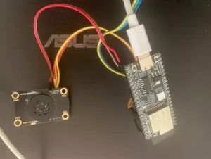
Ai-M61-32S GPIO 接口定义。
| Ai-M61-32S | XFS5152CE |
| 3.3v | VCC |
| GLB_GPIO_PIN_30 | SCL |
| GLB_GPIO_PIN_31 | SDA |
| GND | GND |
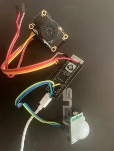
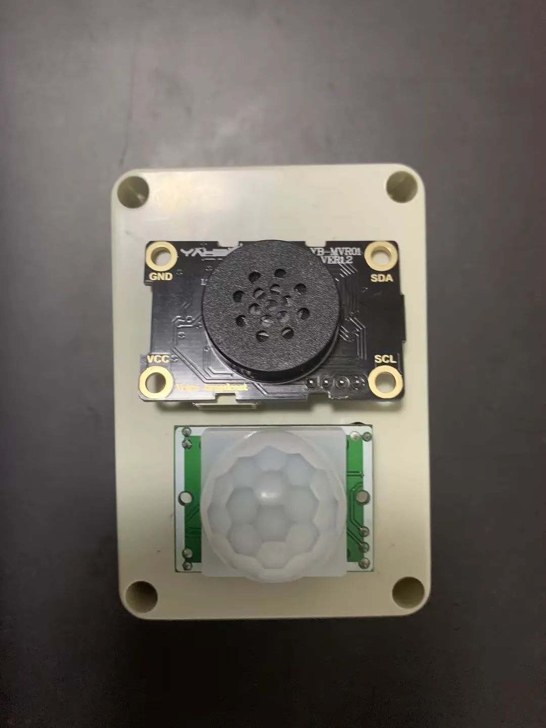
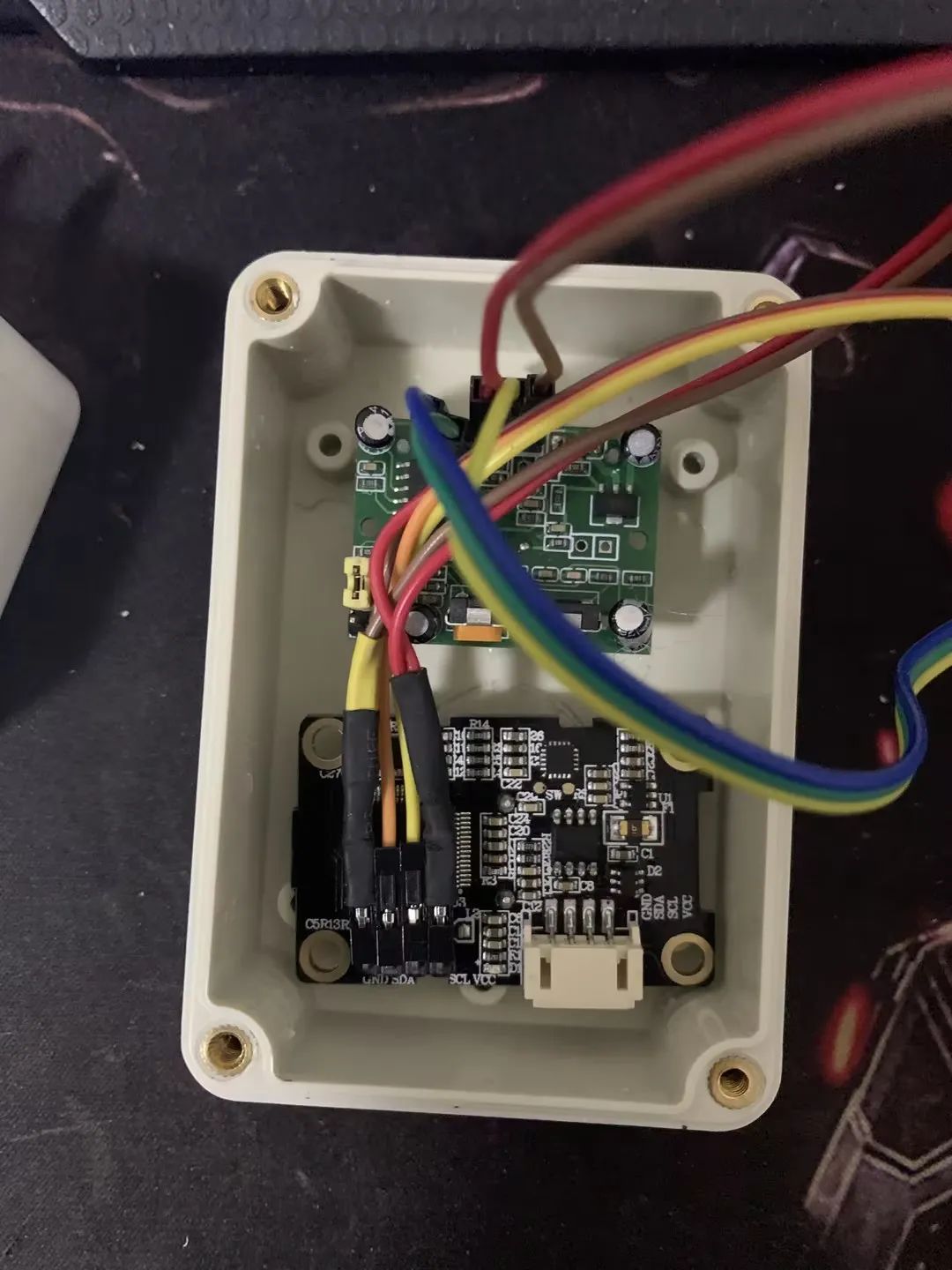
实物图:
连接部分:
红外感应:

完整 组件结构:
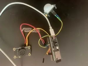
到这里基于 Ai-M61-32S “出门提醒设备 ”软硬件已完成。下一步就是外壳了。
04
外壳
外壳选材小插曲
刷 B 站的时候曾经看过一个防水盒做音箱的视频,就跟着做了一个感觉很有趣。就买了一些防水盒。
某宝签到红包1.5-3块钱,直接抵下来几毛钱一个比 3D 打印什么的性价比高很多。唯一缺点就是外观比较固定。
这个是 DIY 的小音箱。用的是“蓝牙驱动板 m38 蓝牙模块” 4 快多买的。可以蓝牙连接,也可以当 USB 声卡使用还是不错的。侧面改装成了 Type-C 接口,内置了 18650 电池。插着电源开关关掉就可以了。开着开关也没关系。用 mos 管做了隔离。插着线的情况下电池不给设备供电。
拔掉 USB 线,电池供电。基本可以无缝衔接。
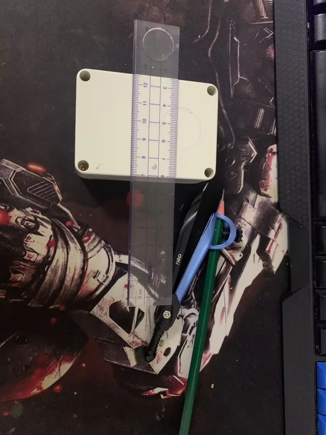
下面言归正传,选用的是 835833mm 尺寸的防水盒,用了给的红包抵扣后价格 0.17 元。还可以。
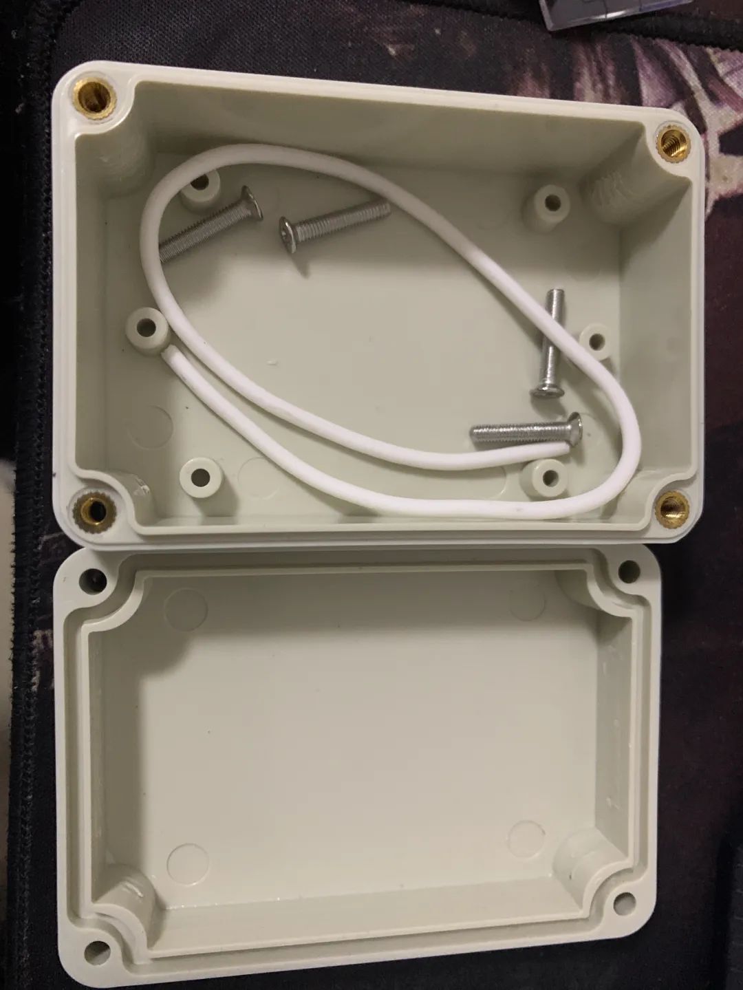
摆了摆感觉尺寸刚刚好。
新铅笔,用小孩儿的卷笔刀削一下。

拿出尺子、圆规。
画上圈圈,定好位置。
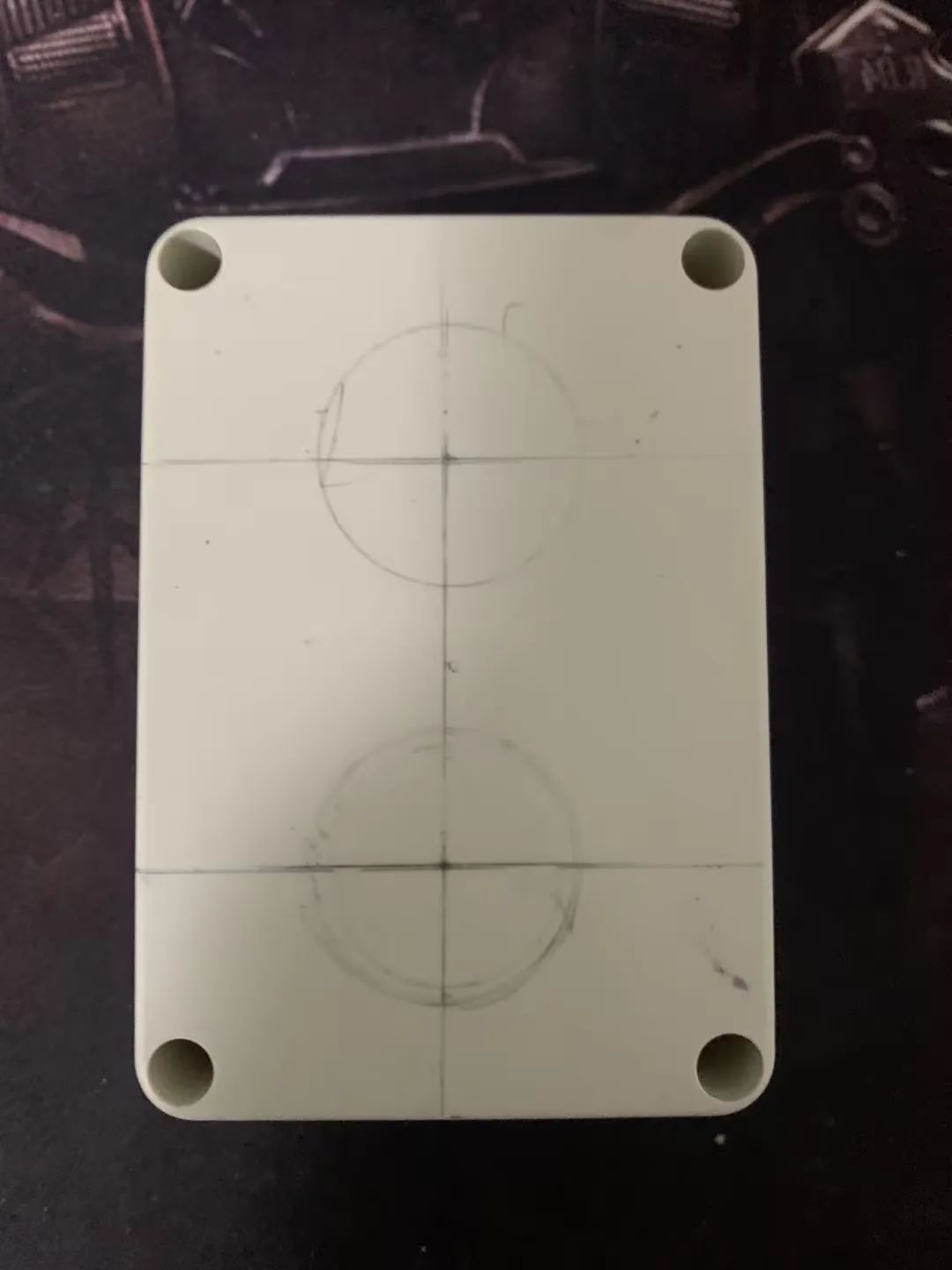
然后拿把剪刀,搞就完了。
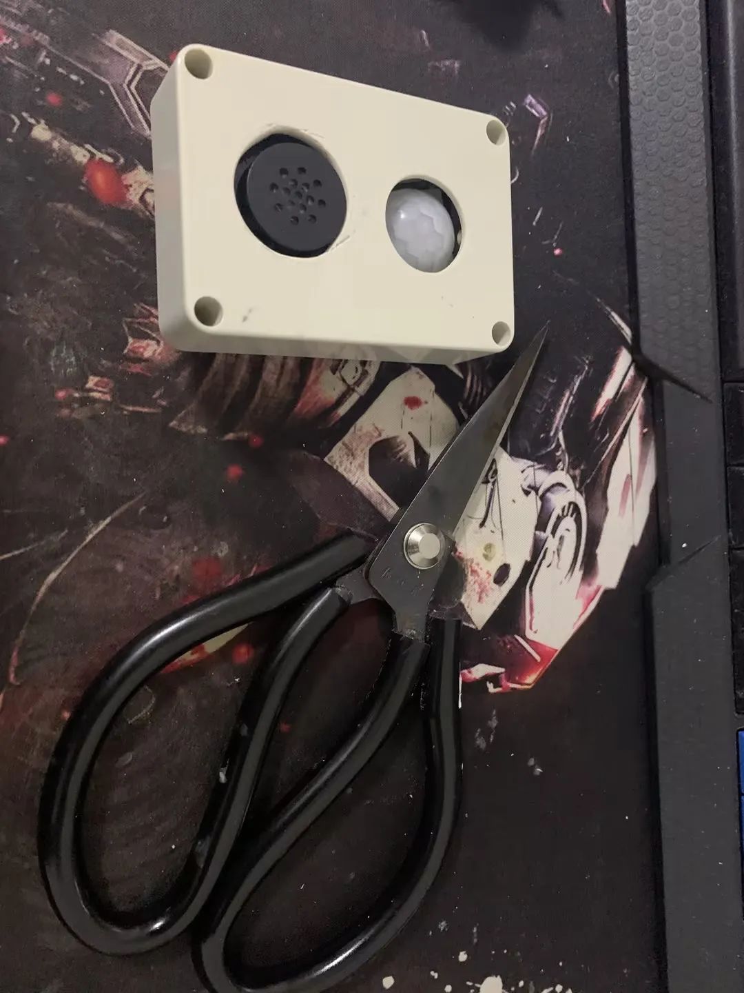
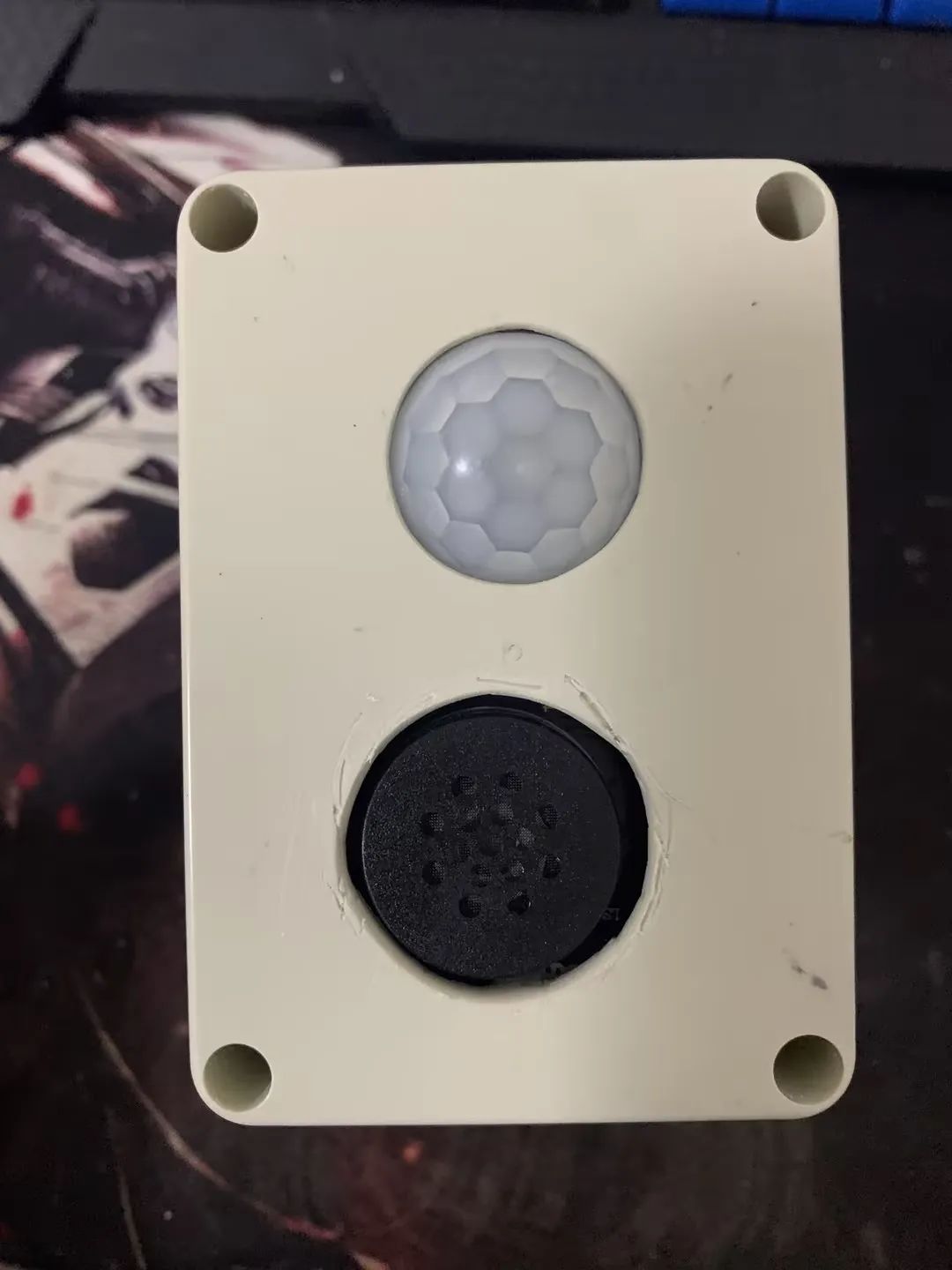
最终效果。下面“ XFS5152CE” 语音合成模块的那个孔开始想用其他方法开孔结果给弄坏了。
最后用剪刀固定一点一直转,圆孔就出来了,也算是涨经验了。
开孔后接线。

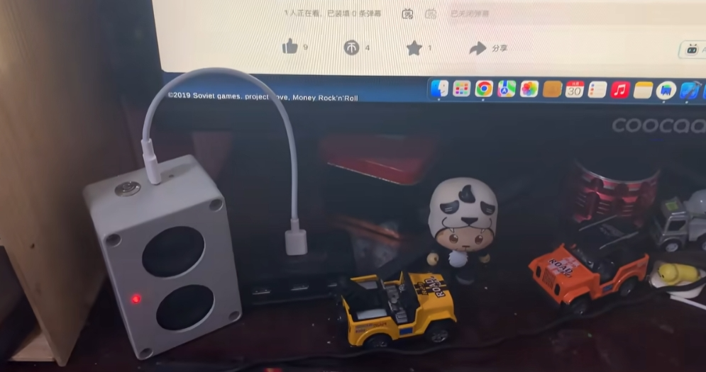
最终效果展示,快来围观!
-
传感器
+关注
关注
2574文章
54438浏览量
786372 -
PIR
+关注
关注
0文章
76浏览量
18615 -
HC-SR501
+关注
关注
9文章
16浏览量
42392
原文标题:【DIY电子作品】基于 Ai-M61-32S做一个出门提醒设备(汇总篇)
文章出处:【微信号:安信可科技,微信公众号:安信可科技】欢迎添加关注!文章转载请注明出处。
发布评论请先 登录
Ai-M61-32S(点灯)
高性能、低功耗、可驱屏,Ai-M61系列模组驱屏能力介绍
介绍两款小安派开源硬件:Cam-U和Cam-D
用Ai-M61-32S开发板能玩出多少拓展板?
安信可Ai-M61-32S开发板能玩出多少拓展板?

晚上再也不摸黑 ,用Ai-M61-32S&Rd-03制作一盏自动感应小夜灯
DIY案例:用Ai-M61-32S做一个多功能书桌灯

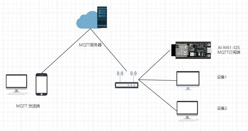
安信可Ai-M61/Ai-M62系列连接AWS亚马逊云
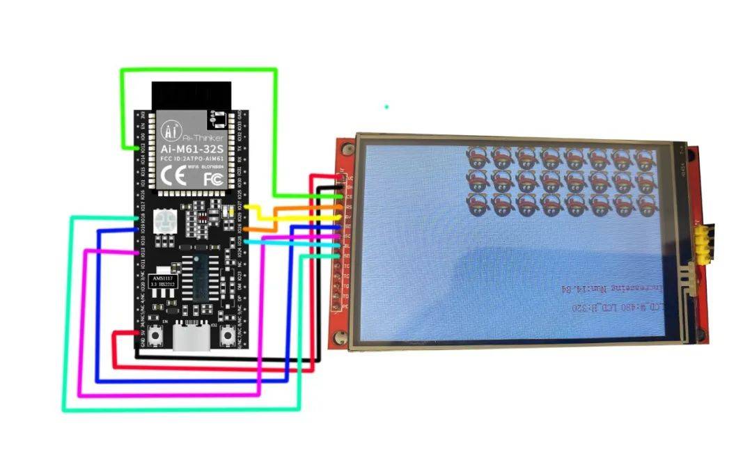
【外设移植】Ai-M61-32s 开发板+3.5寸SPI彩屏
不到10块钱,用Ai-M61-32S如何自制一个开机棒?
能和Ai-M61模组对话了?手搓一个ChatGPT 语音助手


 工商网监
工商网监
评论