 ZYNQ基础---AXI DMA使用

前言
在ZYNQ中进行PL-PS数据交互的时候,经常会使用到DMA,其实在前面的ZYNQ学习当中,也有学习过DMA的使用,那就是通过使用自定义的IP,完成HP接口向内存写入和读取数据的方式。同样Xilinx官方也提供有一些DMA的IP,通过调用API函数能够更加灵活地使用DMA。
1. AXI DMA的基本接口
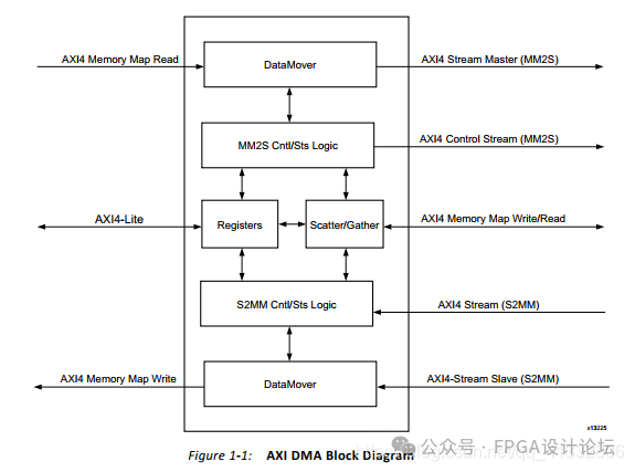
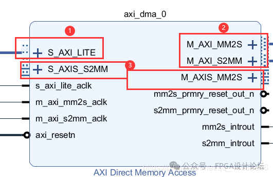
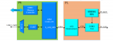
axi dma IP的基本结构如下,主要分为三个部分,分别是控制axi dma寄存器通道,从ddr读出数据通道和向ddr写入数据通道。其IP结构的两边分别对应着用于访问内存的AXI总线和用于用户简单操作的axis stream总线。axi stream总线相较于axi总线来说要简单很多,它没有地址,靠主机和从机之间进行握手来传递数据。
2 Block design搭建
做一个简单的例子来测试一下axi dma。先自定义一个IP,用于缓存从zynq通过axi dma发来的数据,一次突发传输结束之后,将接收到的数据写回到内存中。
2.1 自定义一个IP
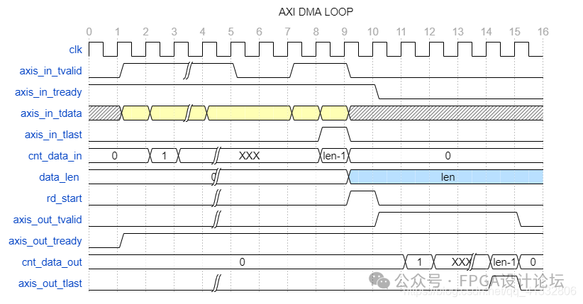
时序设计如下,将接收到的数据缓存到FIFO中,当zynq一次axi stream 传输结束的时候,开始将数据从FIFO中读出,并将数据写入到内存中。
module dma_loop(
//====================================================
//clock and reset
//====================================================
input wire axis_clk ,
input wire rst_n ,
//====================================================
//input axis port
//====================================================
input wire [7:0] axis_in_tdata ,
input wire axis_in_tvalid ,
output wire axis_in_tready ,
input wire axis_in_tlast ,
//====================================================
//output axis port
//====================================================
output wire [7:0] axis_out_tdata ,
output reg axis_out_tvalid ,
input wire axis_out_tready ,
output wire axis_out_tlast
);
//====================================================
//input axis port
//====================================================
wire wr_fifo_en ;
wire rd_fifo_en ;
wire full,empty ;
reg rd_start ;
reg [9:0] cnt_data_in ;
wire add_cnt_data_in ;
wire end_cnt_data_in ;
reg [9:0] data_len ;
reg [9:0] cnt_data_out ;
wire add_cnt_data_out;
wire end_cnt_data_out;
assign wr_fifo_en = axis_in_tvalid & axis_in_tready;
assign axis_in_tready = ~full;
always @(posedge axis_clk or negedge rst_n) begin
if (rst_n==1'b0) begin
rd_start <= 1'b0;
end
else if (axis_in_tvalid & axis_in_tready & axis_in_tlast) begin
rd_start <= 1'b1;
end
else begin
rd_start <= 1'b0;
end
end
//----------------cnt_data------------------
always @(posedge axis_clk or negedge rst_n) begin
if (rst_n == 1'b0) begin
cnt_data_in <= 'd0;
end
else if (add_cnt_data_in) begin
if(end_cnt_data_in)
cnt_data_in <= 'd0;
else
cnt_data_in <= cnt_data_in + 1'b1;
end
end
assign add_cnt_data_in = axis_in_tvalid & axis_in_tready;
assign end_cnt_data_in = add_cnt_data_in && axis_in_tlast;
//----------------data_len------------------
always @(posedge axis_clk or negedge rst_n) begin
if (rst_n==1'b0) begin
data_len <= 'd0;
end
else if (end_cnt_data_in) begin
data_len <= cnt_data_in + 1'b1;
end
end
sfifo_wr1024x8_rd1024x8 inst_sfifo (
.clk(axis_clk), // input wire clk
.din(axis_in_tdata), // input wire [7 : 0] din
.wr_en(wr_fifo_en), // input wire wr_en
.rd_en(rd_fifo_en), // input wire rd_en
.dout(axis_out_tdata), // output wire [7 : 0] dout
.full(full), // output wire full
.empty(empty) // output wire empty
);
//----------------axis_out_tvalid------------------
always @(posedge axis_clk or negedge rst_n) begin
if (rst_n==1'b0) begin
axis_out_tvalid <= 1'b0;
end
else if (end_cnt_data_out) begin
axis_out_tvalid <= 1'b0;
end
else if (rd_start == 1'b1) begin
axis_out_tvalid <= 1'b1;
end
end
//----------------cnt_data_out------------------
always @(posedge axis_clk or negedge rst_n) begin
if (rst_n == 1'b0) begin
cnt_data_out <= 'd0;
end
else if (add_cnt_data_out) begin
if(end_cnt_data_out)
cnt_data_out <= 'd0;
else
cnt_data_out <= cnt_data_out + 1'b1;
end
end
assign add_cnt_data_out = axis_out_tvalid & axis_out_tready;
assign end_cnt_data_out = add_cnt_data_out && cnt_data_out == data_len - 1;
assign axis_out_tlast = end_cnt_data_out;
assign rd_fifo_en = axis_out_tvalid & axis_out_tready;
wire [63:0] probe0;
assign probe0 = {
cnt_data_in ,
cnt_data_out ,
rd_start ,
data_len ,
axis_in_tdata ,
axis_in_tvalid ,
axis_in_tready ,
axis_in_tlast ,
axis_out_tdata ,
axis_out_tvalid ,
axis_out_tready ,
axis_out_tlast
};
ila_0 inst_ila (
.clk(axis_clk), // input wire clk
.probe0(probe0) // input wire [63:0] probe0
);
endmodule
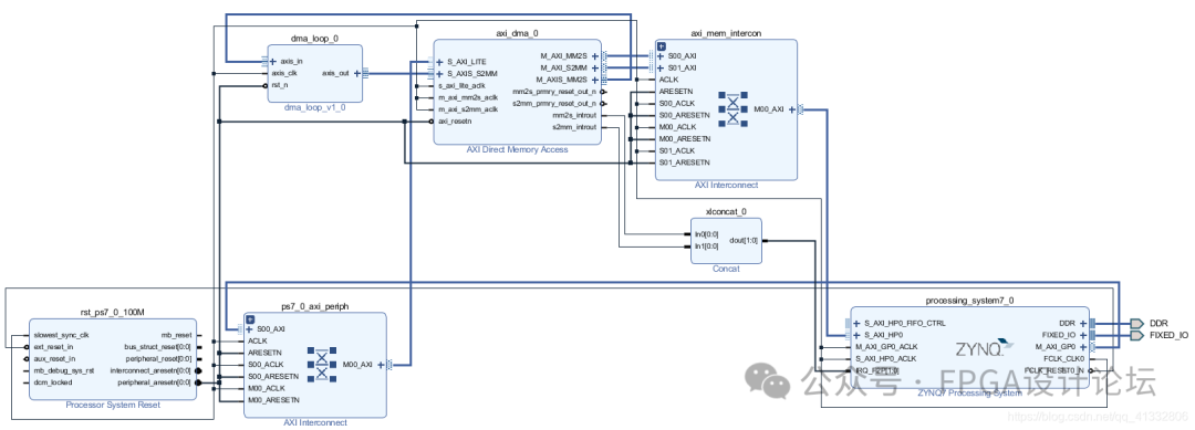
搭建block design
3. vitis
xilinx的东西就有这点优点,基本上fpga里面有的资源,都有一个示例工程,把它导入进来就可以参考一下具体这个外设改怎么来使用了。这个demo里面使用到了串口。串口在前面的串口中断中已经使用到,本次实验需要使用到串口的中断和DMA的中断。
PC的串口向FPGA发送数据,一帧数据发送完成之后,会触发串口的中断。串口中断函数会接收数据,并且记录数据长度。然后将通过DMA将数据写入到自定义的IP当中,自定义IP接收完数据之后,将把数据写回到内存中。
#include
#include "platform.h"
#include "xil_printf.h"
#include "xparameters.h"
#include "xaxidma.h"
#include "xuartps.h"
#include "xscugic.h"
#include "sleep.h"
#define GIC_DEVICE_IDXPAR_PS7_SCUGIC_0_DEVICE_ID
#define UART_DEV_ID XPAR_PS7_UART_1_DEVICE_ID
#define DMA_DEVICE_ID XPAR_AXI_DMA_0_DEVICE_ID
#define UART_INTR_ID XPAR_PS7_UART_1_INTR
#define MM2S_INTR_ID XPAR_FABRIC_AXIDMA_0_MM2S_INTROUT_VEC_ID
#define S2MM_INTR_ID XPAR_FABRIC_AXIDMA_0_S2MM_INTROUT_VEC_ID
XUartPs UartInst;
XScuGic GicInst;
XAxiDma DmaInst;
volatile int TxDone;
volatile int RxDone;
volatile int Error;
u32 UartRxLen = 0;
int UartRxFlag = 0;
u8 * UartRxBuf = (u8 *)(0x2000000);
u8 * UartTxBuf = (u8 *)(0x4000000);
/***********************************
* Uart Init function
**********************************/
int Uart_Init();
/********************************
* DMA initialize function
********************************/
int Dma_Init();
int Setup_Interrupt_System();
void Uart_Intr_Handler(void *CallBackRef, u32 Event, unsigned int EventData);
void Mm2s_Intr_Handler();
void S2mm_Intr_Handler();
int main()
{
init_platform();
Uart_Init();
Dma_Init();
Setup_Interrupt_System();
while(1)
{
/*****************************************************************************
* Uart has receive one frame
*****************************************************************************/
if (UartRxFlag == 1) {
// clear the flag
UartRxFlag = 0;
/*****************************************************************************
* Transfer data from axidma to device
*****************************************************************************/
Xil_DCacheFlushRange((INTPTR)UartRxBuf, UartRxLen);//flush data into ddr
usleep(2);
// transfer data from axi dma to device
XAxiDma_SimpleTransfer(&DmaInst, (UINTPTR)UartRxBuf, UartRxLen, XAXIDMA_DMA_TO_DEVICE);
while(!TxDone);
TxDone=0;//reset txdone flag; complete txtransfer
/*****************************************************************************
* Transfer data from device to dma
*****************************************************************************/
Xil_DCacheInvalidateRange((INTPTR)UartTxBuf, UartRxLen);
usleep(2);
XAxiDma_SimpleTransfer(&DmaInst, (UINTPTR)UartTxBuf, UartRxLen, XAXIDMA_DEVICE_TO_DMA);
while(!RxDone);
RxDone = 0;
XUartPs_Send(&UartInst, UartTxBuf, UartRxLen);
XUartPs_Recv(&UartInst, UartRxBuf, 4096);//reset conter and start recv from uart
}
}
cleanup_platform();
return 0;
}
/*****************************************************************************
* @ function : init uart and set the callback fuction
*****************************************************************************/
int Uart_Init()
{
int Status;
u32 IntrMask;
XUartPs_Config *UartCfgPtr;
UartCfgPtr = XUartPs_LookupConfig(UART_DEV_ID);
Status = XUartPs_CfgInitialize(&UartInst, UartCfgPtr, UartCfgPtr->BaseAddress);
if(Status != XST_SUCCESS)
{
printf("initialize UART failed ");
return XST_FAILURE;
}
/****************************************
* Set uart interrput mask
****************************************/
IntrMask =
XUARTPS_IXR_TOUT | XUARTPS_IXR_PARITY | XUARTPS_IXR_FRAMING |
XUARTPS_IXR_OVER | XUARTPS_IXR_TXEMPTY | XUARTPS_IXR_RXFULL |
XUARTPS_IXR_RXOVR;
XUartPs_SetInterruptMask(&UartInst, IntrMask);
/*****************************************************************************
* Set Uart interrput callback function
*****************************************************************************/
XUartPs_SetHandler(&UartInst, (XUartPs_Handler)Uart_Intr_Handler, &UartInst);
/*****************************************************************************
* Set Uart baud rate
*****************************************************************************/
XUartPs_SetBaudRate(&UartInst, 115200);
/*****************************************************************************
* Set Uart opertion mode
*****************************************************************************/
XUartPs_SetOperMode(&UartInst, XUARTPS_OPER_MODE_NORMAL);
/*****************************************************************************
* Set Uart Receive timeout
*****************************************************************************/
XUartPs_SetRecvTimeout(&UartInst, 8);
/*****************************************************************************
* Start to listen
*****************************************************************************/
XUartPs_Recv(&UartInst, UartRxBuf, 4096);
return Status;
}
void Uart_Intr_Handler(void *CallBackRef, u32 Event, unsigned int EventData)
{
if (Event == XUARTPS_EVENT_RECV_TOUT) {
if(EventData == 0)
{
XUartPs_Recv(&UartInst, UartRxBuf, 4096);
}
else if(EventData > 0) {
UartRxLen = EventData;
UartRxFlag = 1;
}
}
}
/*****************************************************************************
* @ function : init Axi DMA
*****************************************************************************/
int Dma_Init()
{
int Status;
XAxiDma_Config * DmaCfgPtr;
DmaCfgPtr = XAxiDma_LookupConfig(DMA_DEVICE_ID);
Status = XAxiDma_CfgInitialize(&DmaInst, DmaCfgPtr);
if(Status != XST_SUCCESS)
{
printf("initialize AXI DMA failed ");
return XST_FAILURE;
}
/*****************************************************************************
* Disable all the interrupt before setup
*****************************************************************************/
XAxiDma_IntrDisable(&DmaInst, XAXIDMA_IRQ_ALL_MASK, XAXIDMA_DEVICE_TO_DMA);
XAxiDma_IntrDisable(&DmaInst, XAXIDMA_IRQ_ALL_MASK, XAXIDMA_DMA_TO_DEVICE);
/*****************************************************************************
*Enable all the interrput
*****************************************************************************/
XAxiDma_IntrEnable(&DmaInst, XAXIDMA_IRQ_ALL_MASK, XAXIDMA_DEVICE_TO_DMA);
XAxiDma_IntrEnable(&DmaInst, XAXIDMA_IRQ_ALL_MASK, XAXIDMA_DMA_TO_DEVICE);
return Status;
}
/*****************************************************************************/
/*
*
* This is the DMA TX Interrupt handler function.
*
* It gets the interrupt status from the hardware, acknowledges it, and if any
* error happens, it resets the hardware. Otherwise, if a completion interrupt
* is present, then sets the TxDone.flag
*
* @paramCallback is a pointer to TX channel of the DMA engine.
*
* @returnNone.
*
* @noteNone.
*
******************************************************************************/
void Mm2s_Intr_Handler(void *Callback)
{
u32 IrqStatus;
int TimeOut;
XAxiDma *AxiDmaInst = (XAxiDma *)Callback;
/* Read pending interrupts */
IrqStatus = XAxiDma_IntrGetIrq(AxiDmaInst, XAXIDMA_DMA_TO_DEVICE);
/* Acknowledge pending interrupts */
XAxiDma_IntrAckIrq(AxiDmaInst, IrqStatus, XAXIDMA_DMA_TO_DEVICE);
/*
* If no interrupt is asserted, we do not do anything
*/
if (!(IrqStatus & XAXIDMA_IRQ_ALL_MASK)) {
return;
}
/*
* If error interrupt is asserted, raise error flag, reset the
* hardware to recover from the error, and return with no further
* processing.
*/
if ((IrqStatus & XAXIDMA_IRQ_ERROR_MASK)) {
Error = 1;
/*
* Reset should never fail for transmit channel
*/
XAxiDma_Reset(AxiDmaInst);
TimeOut = 10000;
while (TimeOut) {
if (XAxiDma_ResetIsDone(AxiDmaInst)) {
break;
}
TimeOut -= 1;
}
return;
}
/*
* If Completion interrupt is asserted, then set the TxDone flag
*/
if ((IrqStatus & XAXIDMA_IRQ_IOC_MASK)) {
TxDone = 1;
}
}
/*****************************************************************************/
/*
*
* This is the DMA RX interrupt handler function
*
* It gets the interrupt status from the hardware, acknowledges it, and if any
* error happens, it resets the hardware. Otherwise, if a completion interrupt
* is present, then it sets the RxDone flag.
*
* @paramCallback is a pointer to RX channel of the DMA engine.
*
* @returnNone.
*
* @noteNone.
*
******************************************************************************/
void S2mm_Intr_Handler(void *Callback)
{
u32 IrqStatus;
int TimeOut;
XAxiDma *AxiDmaInst = (XAxiDma *)Callback;
/* Read pending interrupts */
IrqStatus = XAxiDma_IntrGetIrq(AxiDmaInst, XAXIDMA_DEVICE_TO_DMA);
/* Acknowledge pending interrupts */
XAxiDma_IntrAckIrq(AxiDmaInst, IrqStatus, XAXIDMA_DEVICE_TO_DMA);
/*
* If no interrupt is asserted, we do not do anything
*/
if (!(IrqStatus & XAXIDMA_IRQ_ALL_MASK)) {
return;
}
/*
* If error interrupt is asserted, raise error flag, reset the
* hardware to recover from the error, and return with no further
* processing.
*/
if ((IrqStatus & XAXIDMA_IRQ_ERROR_MASK)) {
Error = 1;
/* Reset could fail and hang
* NEED a way to handle this or do not call it??
*/
XAxiDma_Reset(AxiDmaInst);
TimeOut = 10000;
while (TimeOut) {
if(XAxiDma_ResetIsDone(AxiDmaInst)) {
break;
}
TimeOut -= 1;
}
return;
}
/*
* If completion interrupt is asserted, then set RxDone flag
*/
if ((IrqStatus & XAXIDMA_IRQ_IOC_MASK)) {
RxDone = 1;
}
}
/*****************************************************************************
* @ function : Set up the interrupt system
*****************************************************************************/
int Setup_Interrupt_System()
{
int Status;
XScuGic_Config * GicCfgPtr;
GicCfgPtr = XScuGic_LookupConfig(GIC_DEVICE_ID);
Status = XScuGic_CfgInitialize(&GicInst, GicCfgPtr, GicCfgPtr->CpuBaseAddress);
if(Status != XST_SUCCESS)
{
printf("initialize GIC failed ");
return XST_FAILURE;
}
/*****************************************************************************
* initialize exception system
*****************************************************************************/
Xil_ExceptionInit();
/*****************************************************************************
* register interrput type exception
*****************************************************************************/
Xil_ExceptionRegisterHandler(XIL_EXCEPTION_ID_INT,(Xil_ExceptionHandler)XScuGic_InterruptHandler, &GicInst);
/*****************************************************************************
* connect interrput to scugic controller
*****************************************************************************/
Status = XScuGic_Connect(&GicInst, UART_INTR_ID, (Xil_ExceptionHandler) XUartPs_InterruptHandler, &UartInst);
if(Status != XST_SUCCESS)
{
printf("Connect Uart interrput to GIC failed ");
return XST_FAILURE;
}
Status = XScuGic_Connect(&GicInst, MM2S_INTR_ID, (Xil_ExceptionHandler) Mm2s_Intr_Handler, &DmaInst);
if(Status != XST_SUCCESS)
{
printf("Connect DMA tx interrput to GIC failed ");
return XST_FAILURE;
}
Status = XScuGic_Connect(&GicInst, S2MM_INTR_ID, (Xil_ExceptionHandler) S2mm_Intr_Handler, &DmaInst);
if(Status != XST_SUCCESS)
{
printf("Connect DMA tx interrput to GIC failed ");
return XST_FAILURE;
}
/*****************************************************************************
* Enable the interrput
*****************************************************************************/
XScuGic_Enable(&GicInst, UART_INTR_ID);
XScuGic_Enable(&GicInst, S2MM_INTR_ID);
XScuGic_Enable(&GicInst, MM2S_INTR_ID);
/*****************************************************************************
* Enable the exception system
*****************************************************************************/
Xil_ExceptionEnable();
return Status;
}
测试结果
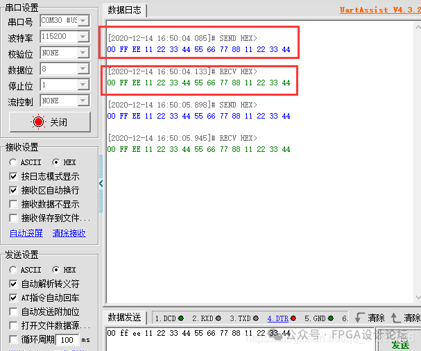
从串口发出的数据被成功的接收。再看看ila抓取到的波形。
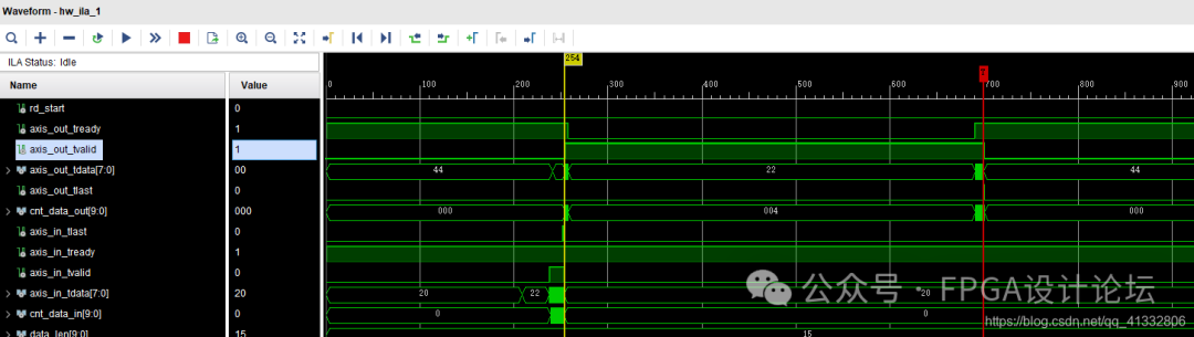
输入到自定义IP的数据:

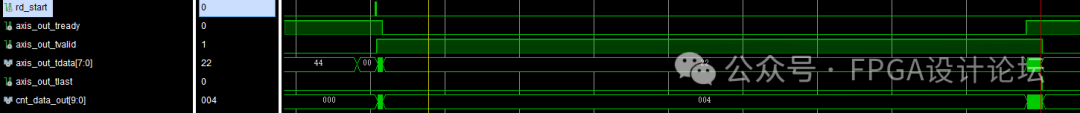
从自定义IP输出的数据。一次传输之间隔了较长的时间。
原文链接:
https://openatomworkshop.csdn.net/67401f383a01316874d6e783.html
-
dma
+关注
关注
3文章
584浏览量
106391 -
AXI
+关注
关注
1文章
145浏览量
18063
原文标题:ZYNQ基础---AXI DMA使用
文章出处:【微信号:gh_9d70b445f494,微信公众号:FPGA设计论坛】欢迎添加关注!文章转载请注明出处。
发布评论请先 登录
Xilinx高性能低延时8通道PCIe-DMA控制器IP,SGDMA,QDMA,CDMA,RDMA, V4L2驱动,高速视频采集, 高速AD采集
利用开源uart2axi4实现串口访问axi总线

基于AXI DMA IP核的DDR数据存储与PS端读取
使用AXI4接口IP核进行DDR读写测试
Xilinx高性能NVMe Host控制器IP+PCIe 3.0软核控制器IP,纯逻辑实现,AXI4和AXI4-Stream DMA接口,支持PCIe 3.0和4.0
利用蜂鸟E203搭建SoC【5】——DMA使用
将e203 例化AXI总线接口
NVMe高速传输之摆脱XDMA设计42:DMA 读写功能验证与分析
双Zynq MPSoC PS侧PCIe高速DMA互连解决方案
AXI GPIO扩展e203 IO口简介
基于E203的DMA ip的使用
关于AXI Lite无法正常握手的问题
RDMA简介8之AXI分析


评论