 简化5G基本收发器电台发射机阵容的设计和评估

摘要
借助无线通信标准,例如LTE和5G,对较高的数据速率和光谱效率的重点促使无线原始设备制造商(OEM)采用新的传输格式,例如正交频施加多元化(OFDM)。但是,这些信号在其信封中具有较大的波动,由于其高峰值功率比(PAPR)而尤其容易受到非线性功率放大器(PA)畸变的影响。使用该高PAPR信号,PA非线性可以产生大量的信号扭曲,从而增加了位错误率(BER)并因此而降低了信噪比。本文回顾了PAPR,它们起源于其中,如何分解发射阵容的RF组件,以及如何摆脱它们或至少减轻其对信号链的影响。
介绍
较新的调制格式(例如OFDM)和各种形式的正交振幅调制(QAM)在信号信封中具有较大的波动。这会在信号中产生高papr。在非线性PA上播放高PAPR信号会产生光谱再生。光谱再生是指由增益压缩引起的新频率,而不是在原始输入中。高papr会导致带内变形,从而降低了整个系统的BER性能。我们将讨论一种解决方案,以帮助找到使用数字预性(DPD)和降低峰值因子(CFR)发动机之间的效率和线性之间的正确系统权衡。
OFDM调制 - 每个人都在这样做!
在LTE和5G系统中,正在并行传输几个载体的载体聚集用于提高带宽和数据速率。这些网络杠杆OFDM调制是一种非常熟练且使用广泛使用的多载波传输技术,可以提高光谱效率并降低多路径反射对接收器解码信号的能力的影响。使用OFDM,最终波形是携带信息的子载波的正交总和,每个子载波都有其自己的中心频率和调制方案。在时间域中,有时这些子载波的峰可以对齐以产生一个巨大的OFDM波形峰。OFDM的一个独特特征是,子载波波形是正交组合的,因此一个子载波的空null(或零振幅)与图1所示的其他子载波的峰值相吻合。这提供了通道带宽相对有效的使用,从而与传统的单一单位模块相比,相对有效地使用了该通道带宽。
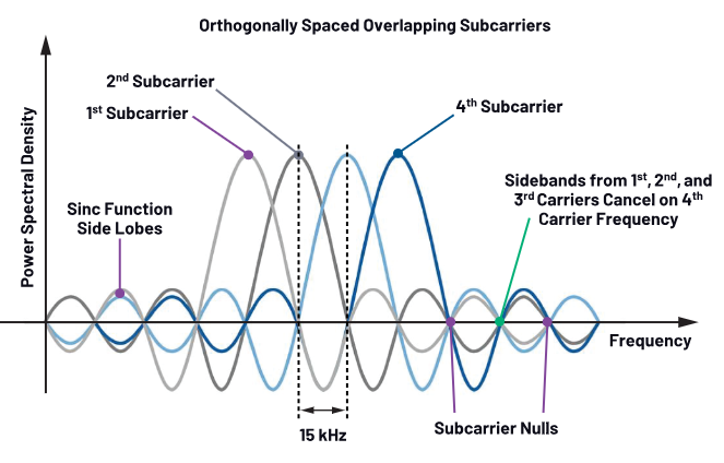
图1 DM子载体波形的多载体。
OFDM还有其他几个好处,包括其对多径褪色的稳健性。但是,OFDM调制的主要问题之一是传输波形遭受高papr的影响。图2显示了各种普通移动技术或调制类型的PAPR。可以观察到,随着新标准或调制技术的出现,典型的PAPR一直在稳步增加。
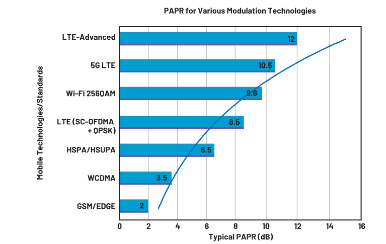
图2。各种调制技术的典型PAPR。
ofm信号
如前所述,由OFDM调制启用的载波聚集用于提高5G系统中的带宽和数据速率。 OFDM还会产生信号的信号,其信封是非构恒定的,这可能会导致较高的PAPR,这可能会导致系统损坏。如果RF信号系列(尤其是PA)中的RF功率组件不能适当地指定以处理预期的电压峰,则这些组件可能会失败。一个大的PAPR通过将PA的效率推向饱和,从而降低了PA的效率,即其非线性工作区域,导致失真导致信号的光谱扩散。对于非稳定 - 内玻璃数字调制方案而言,PA的线性一直是一个关键的设计问题。图3显示了一个时域LTE 64-QAM信号,该信号在ADRV9040的发射器输出。
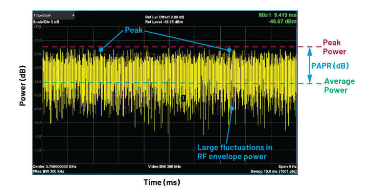
图3。造成大峰的子载波的正交求和的例证。
互补分布函数
由于其形式,OFDM信号需要采用统计方法进行适当的测量。补充累积分布函数(CCDF)用于评估RF信号链中的PAPR降低性能。图4a显示了LTE下行链路10 MHz带宽和64个QAM子载波调制信号的传输波形。图4b中的CCDF显示,信号功率在0.01%的时间内至少超过7.4 dB。理论最大峰值出现在0%的概率上,该概率在此图上不确定。该痕量在约7.4 dB的PAPR处与X轴(0.01%或概率为10E ^-4^ )相交。这表明每10,000个中的一个样本预计将超过7.4 dB的平均功率。
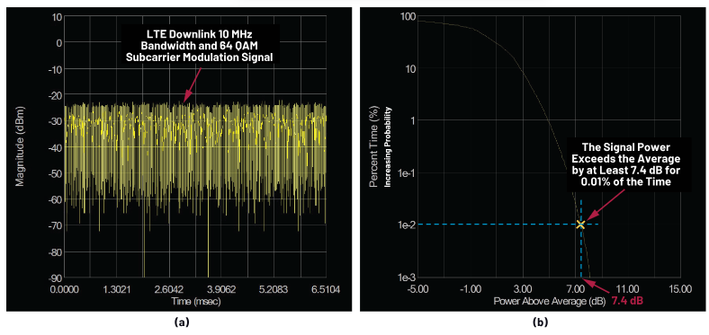
图4。具有10 MHz带宽和64个QAM子载波调制的LTE下行链路的CCDF。
仔细观察CCDF图后,观察Y轴是累积的概率,通常在对数刻度上绘制。 X轴是DB中绘制的功率。该图显示信号功率超过平均功率或高于平均功率的概率或时间百分比。从本质上讲,对于每个功率水平,CCDF图描述了信号在平均功率水平以上的时间。随着CCDF曲线向右移动,我们的峰值功率与平均功率的比率增加。
CCDF图可验证线性操作,并且在PA之后更常见。与通常在不同功率水平下增益变化的方法相比,它可以更准确地描述信号压缩。波峰因子发生的统计分析使其成为设计人员评估放大器压缩对系统BER和/或误差矢量幅度(EVM)的影响的宝贵工具。
那么,为什么PAPR很重要?
PAS本质上是非线性的,在线性和效率之间表现出权衡。常见的非线性问题是增益压缩和相失真,包括带外和带外变形。这些因素中的每一个都会降低系统的性能,并创建带外光谱再生,从而导致相邻的渠道干扰,并违反了监管机构规定的带外排放标准。
在测试PA时,输入幅度逐渐增加,直到测得的比率降低1 dB,代表1 dB增益压缩。 1 dB压缩点是功绩的关键图形,它为RF设计师提供了有关其放大器性能的假设。从本质上讲,放大器的1 dB压缩点被定义为从其小信号值降低设备增益下降1 dB的输出功率。该参数通常用作放大器非线性开始的参考点,大约等于放大器的最大可用峰输出功率。这就是为什么许多RF设计人员通常估计其PA的最大工作输出功率比其1 dB压缩点低几dB的原因。这使得在PA的1 dB压缩点成为关键练习,为了使PAPR高的信号永远不会饱和PA。 PAPR的另一个名称是波峰因素。图5显示了所示的1 dB压缩点的AM-AM曲线。
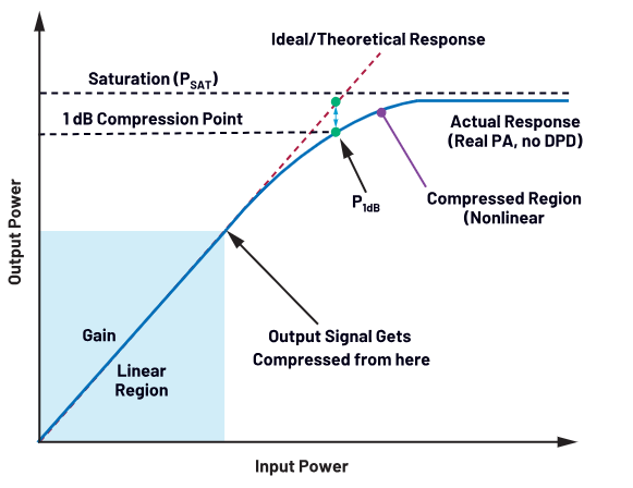
图5。具有1 dB压缩点的AM-AM曲线。
现在,设计师已经评估了PA并确定了其1 dB的压缩点,他们需要在其线性区域中以输入功率向后进行操作PA(例如,在其工作曲线的线性部分内以较低的功率操作PA)以避免光谱增长,对吗?好吧,不完全是!
仅仅备份了远离PA的饱和点的输入,肯定可以帮助避免讨论的所有非线性问题,但会导致非常低的效率并增加散热耗散。通过增加系统的功耗来解决这种低效率问题并不是可行的权衡。如图2所示,随着标准机构具有新的调制方案的创新性,可以更好地利用现有频谱,这导致信号具有越来越高的波峰因素。因此,从长远来看,使用PA返回实施策略将不起作用。本文的下一个部分将讨论两种实施策略,结合在一起,将使PA运行到其饱和点,同时仍保持良好的线性性并大大提高其效率。第一个使用振幅剪切技术来减少PAPR,第二种方法是将PA在其预期功率范围内的非线性响应线性化。
非常成功的数字前端解决方案的两个功能
在无线数字前端(DFE)系统中,涵盖了广泛的子系统,包括DPD,Digital Upconversion(DUC),数字下降转换(DDC)和CFR。还有其他重要领域,例如DC偏移校准,脉搏形成,图像排斥,数字混合,延迟/增益/不平衡补偿,误差校正和其他相关块。 DPD电路使用PA输出处捕获的数据来线性化PA输出。 DPD通过允许PAS更有效地操作来改善系统线性,而CFR有助于限制信号PAPR。使用CFR减少信号的动态范围后,使用DPD发动机,并允许PA在线性区域上方操作。尽管这些块中的每个块涵盖了DFE的关键功能,但本文的这一部分将仅关注CFR和DPD块。
波峰因子降低
OFDM波形的大多数输入信号将在PA的线性范围内。但是,如前所述,该信号的峰值可能超过PA的线性工作范围,由于其对系统损害的贡献,它引起了长期可靠性问题。同样,非常需要在不饱和的情况下以最高输入功率驱动PA。为了避免由于峰值而导致的饱和度,使用了CFR,而不是衰减整个信号,而是减弱了PA线性范围以上信号的部分。简而言之,CFR有助于保持PA线性。
抑制峰时,这会导致恒定的输出功率,从而确保信号保持在PA的线性范围内。请注意,CFR不是线性化技术,而是一种效率提高方案。 CFR凭借其最有效的实施,消除了发射信号的峰值,以降低峰与平均比率,同时遵守所需的光谱发射掩码,相邻的通道功率比和EVM规格。图6显示了检测到的信号峰高于阈值水平。峰的幅度降低至低于某些目标值。这通常是过滤以重塑信号频谱。
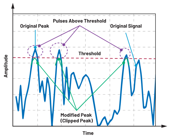
图6。检测到的信号峰高于阈值。
CFR的缺点是剪辑会导致带内信号失真,导致BER性能下降和带外辐射,从而将带外干扰信号施加到相邻的通道上。简而言之,剪辑的后果是信号ACLR和EVM差。过滤夹板信号通常用于以峰值再生成本减少带外辐射。
数字预性
使用DPD,可以将PA推动以直至饱和区域,而不会损害其线性特性。 DPD允许RF设计人员在PA的有效但非线性区域操作其系统,同时保留OFDM调制所需的发送信号线性。换句话说,使用DPD,PA的线性区域扩展了。 DPD发动机通过对PA的逆AM-AM和AM-PM特性进行建模来产生预性系数。本质上,DPD专注于提高PA在其峰值效率点运行时产生的信号的质量。 DPD旨在引入弥补PA增益的反非线性。这是一种通过将精确的反抗原引入输入波形,以补偿PA的带内非线性产品的输入波形,以提高非线性PA的线性。图7显示了DPD线性化PA响应的概念。
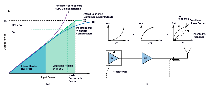
图7。用于线性化PA响应的DPD的通用概念:(a)典型的AM-AM曲线显示整个线性区域为绿色; (b)DPD的基本概念及其如何提高功率放大器效率。
它根据预测数字域中的传输数据的原理来取消模拟域中的PA压缩引起的失真。 DPD的方法可以从简单的解决方案(例如基本查找表(LUT))到更复杂的实时信号处理方法。 DPD实现可以分类为具有内存的无内存模型和模型。
无内存的DPD
无内存的DPD仅基于当前样本来纠正智商样本的幅度和相位。严格无记忆的PA可以以AM-AM和AM-PM转换为特征。这种瞬时非线性通常以PA的AM-AM和AM-PM响应为特征,其中PA输出的输出信号振幅和相位偏差作为其当前输入幅度的函数。因此,可以通过其AM-AM和AM-PM响应来表征无内存的PA。这些测量用于创建将每个输入功率/相组合与产生所需线性输出所需的功率/相相关联的LUT数据。无内存DPD的优点是它可以作为查找表实现相对简单。图7a和7b显示了具有和没有DPD校正的PA的AM-AM响应,应用于2×100 MHz,400 MHz带宽4096样品数据集。
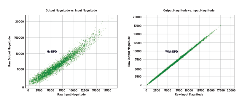
图8。在2×100 MHz,400 MHz带宽信号上具有和不带DPD的PA的AM-AM响应。
带有内存的DPD
随着传输信号带宽的变化,PA将开始表现出记忆效应。这些是某些组件中的频率响应,例如偏置网络,解耦电容器,电源电路,或可以归因于活动设备的热常数。结果,PA的当前输出不仅取决于当前输入,还取决于过去的输入值。在这种情况下,这意味着PA已成为具有内存的非线性系统。带有内存的DPD基于以前的几个样本及其相互依赖性,纠正了iQ数据样本的振幅和阶段。 PA的响应通常不仅取决于当前信号振幅,还取决于先前样品的幅度。因此,数字预性也需要具有内存结构,这是DPD的数学骨干。 Volterra系列是具有内存的非线性最通用的多项式类型,用于模拟具有内存的非线性系统。因此,引入内存的最通用方法是使用Volterra系列。有关与Volterra系列的建模PA失真背后的数学细节的精心讨论,该系列超出了本文的范围,请参阅Masterson(2022)。这超出了本文的范围,请参考Masterson(2022)。这超出了本文的范围,请参考Masterson(2022)。^2^
轻松设计5G RF信号链的框架
ADRV9040 RF收发器提供了一个简化的框架,可轻松设计,实现和测试5G通信系统的RF信号链阵容。一个离散的大型MIMO系统需要以其离散的部署形式进行四个芯片级别,包括RF收发器,DFE FPGA,基带FPGA/ASIC和控制FPGA。由于该收发器附带了DFE集成,因此它消除了对竞争性离散解决方案中使用的几种FPGA的需求,在该解决方案中,在计算机代码中实现了DPD,CFR,DUC和DDC块。 FPGA的实施通常是昂贵的,并且饥饿。这款高度集成的RF收发器有助于消除这种渴望强力的专用FPGA。在本文的这一部分中,我们强调了该RF收发器和提议的框架,用于检查典型的PA增益阵容并通过在设备内实现寄存器写入噪声限制的理智检查。
芯片(SOC)上的这种高度集成的射频敏捷收发器系统提供了八个发射器,两个用于监视发射机通道的观察接收机,八个接收器,集成的本地振荡器(LO)和时钟合成器以及数字信号处理功能,以提供具有重要数字前端能力的完整收集器。该设备提供了由小细胞无线电单元(RUS),宏观4G/5G RUS和大量MIMO RUS所需的高无线电性能和低功耗。完整的收发器子系统包括自动和手动衰减控制,DC偏移校正,正交误差校正和数字过滤。收发器具有完全集成的数字前端,该数字前端支持一些关键块,包括DPD(最多400 MHz IBW),高性能的三阶段CFR发动机,集成的数字下调和数字上转换都能够支持多达八个组件载体。该设备适用于带有小型单频段,多波段,TDD Massive Mimo和TDD/FDD的此类部署/应用程序。图9显示了一个高级功能框图。
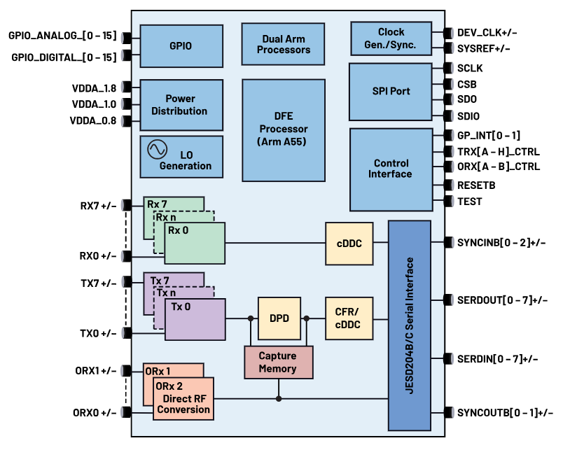
图9。ADRV9040高级功能框图。
基于ZIF的体系结构
ADRV9040的发射和接收信号路径使用零IF(ZIF)体系结构,该体系结构提供宽带宽度,具有适用于非连续多载波RU应用程序的动态范围。 ZIF架构具有低功率加上RF频率和带宽敏捷性的好处。该体系结构提供了比离散解决方案的尺寸,重量和功率优势。该体系结构使OEM能够设计最小,最轻的5G巨大MIMO收音机40%轻40%,能源效率高约10%。对完整的小信号无线电板的分析表明,ZIF体系结构可以在RF BOM与简单导数RU上节省大量成本(PER 32T32R)。
零IF体系结构还以LO频率传输能量。由于智商混合和数据路径的差异,引入了正交和LO泄漏误差(例如,载体不集中在LO上)(例如,两个混合器从未真正具有相同的特征)。在多载波和不对称载体应用中,这是一个更大的问题。为了减少这种不需要的发射,收发器具有TX LO泄漏校正算法,该算法都用于初始校准,然后是在运行时操作期间使用的跟踪校准。
CFR块
该设备的CFR有助于保持PAS线性。这种低功率CFR发动机可帮助设计人员降低输入信号的峰值与平均值,从而使效率更高的传输线路UPS。如前所述,校正峰的光谱再生始终是CFR的关注点。至关重要的是,ADRV9040在优化算法中起着至关重要的作用,以确保CFR块的影响与OEM的系统规格保持一致。理想的CFR块具有非常低的延迟,零缺少峰值。
图10显示了5G新无线电(NR)信号上PAPR降低的结果。 PER-CFR(左)图显示了峰值压缩,这是由输出信号的CCDF(黄色痕迹)以陡峭的速率掉落的,而随着PAPR的增加,高斯参考ccdf(绿色痕迹)的速度较高。另一方面,CFR后(右)图显示了其CCDF与高斯信号相似的5G NR信号。
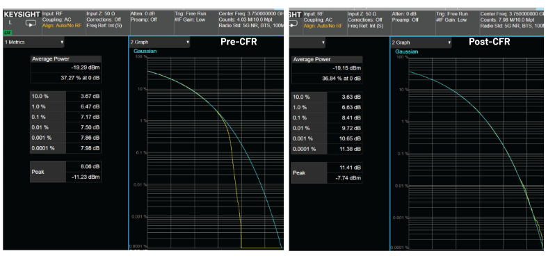
图10。5GNR信号在应用CFR之前和之后。
通过从检测到的峰中减去预定的脉冲以使信号在PA的线性范围内,使用脉冲取消技术的变体实现此CFR。 CFR块由CFR发动机的三个副本组成,每个副本都使用检测阈值来检测峰和校正阈值,而检测到的峰被减弱。这些频谱校正脉冲从数据流中减去,以使信号在PA的线性范围内。校正脉冲需要在光谱上形状,以将噪声泄漏到相邻的频段中。 ADRV9040可以容纳两个校正脉冲,同时对应于设备上的两个不同的载波配置。这些校正脉冲可以预加载,并允许设备在即时两种载波配置之间进行切换。
DPD
该设备包含一个完全集成的低功率DPD引擎,用于RF信号链线性化应用。该引擎提供行业领先的DPD性能。如所讨论的,介绍记忆的最通用方法是使用Volterra系列。该DPD发动机基于广义记忆多项式(GMP)和动态偏差(DDR)的缩写实现,它们是众所周知的Volterra系列的广义子集。在收发器的用户指南和其他设计侧支中详细讨论了ADRV9040中使用的广义内存多项式。通过DPD执行器硬件将逆PA模型(PA ^-1^ )应用于插值数字基带样本。专用的嵌入式^ARM®Cortex®^^^A55处理器用于计算GMP系数。 DPD执行器是可编程的多项式计算器。图11显示了应用于插值数字基带样品的PA ^-1模型。^
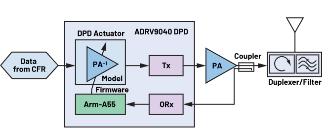
图11。将逆PA模型应用于插值的数字基带样品。
该DPD算法支持间接学习和直接学习DPD机制,用于提取DPD模型系数。间接学习涉及使用观察接收器数据作为预测与参考相对应的输入样本的参考,而直接学习涉及使用DPD前执行器发送信号作为参考以最大程度地减少观察到的参考数据之间的误差。两者之间的区别在于,间接学习算法是时间效率的,但是直接学习算法更准确,因为它需要更长的时间来收敛。在不需要DPD的系统应用中,ADRV9040提供了一种通过GPIO控制绕过预性的机制。图12显示了在20 MHz LTE信号中使用DPD后ACLR的功率谱密度提高。通过在右图上使用DPD,消除了左图所示的ACLR的障碍。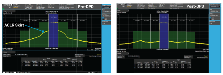
图12。功率光谱密度显示DPD后ACLR的改善。
电源管理注意事项
使用正确的功率解决方案设计ADRV9040对于避免在TDD接收到传输过渡和实现最佳RF性能的问题之类的问题至关重要。 ADI SilentSwitcher®^技术^提供了多种区别,包括高切换频率,超低RMS噪声和点噪声。无声切换器3功率设计需要更少的组件,小的PCB足迹(尺寸),最重要的是一个更快且控制良好的瞬态沉降时间,从而导致超值EMI排放。图13显示了带有一些建议的功率IC的宏基站的高级框图,LT8627SP 和ADM7172 用于为ADRV9040电压导轨提供动力。
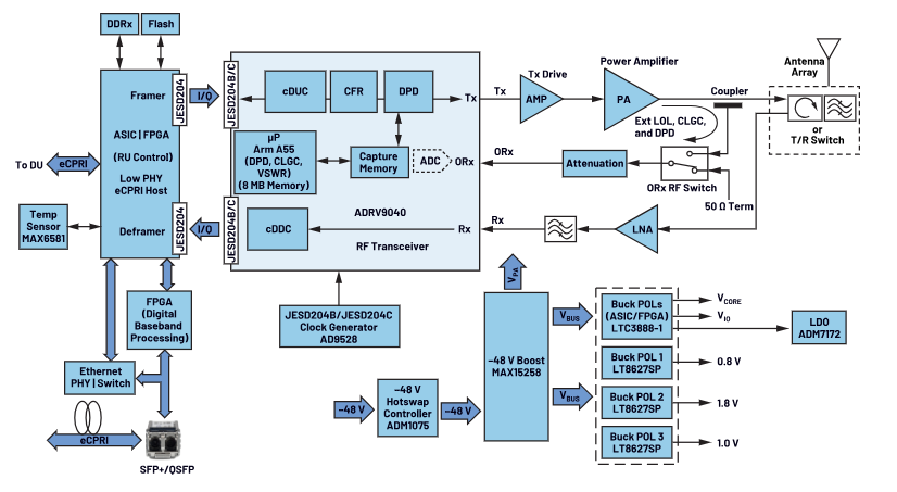
图13。具有ADRV9040功率解决方案的宏RRH的系统级框图。
ADS10-V1EBZ和ADRV904X-MB/PCBZ评估平台
ADRV9040评估平台有助于建立一个简单明了的框架,用于测试用户的设计。图14呈现 ADS10-V1EBZ (主板)和ADRV904X-MB/PCBZ评估板。请联系您的ADI销售代表以订购您的评估系统。 RF设计师只需要将其设备连接到Eval平台即可捕获不同的图,而ADRV9040进行了繁重的举重,以通过Data Byte将其写入其寄存器中找到最佳性能配置。
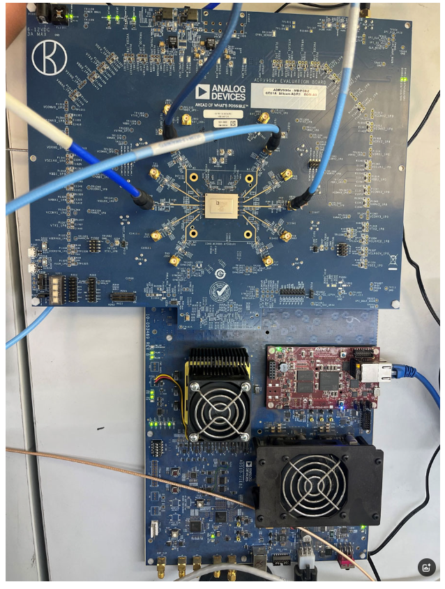
图14。ADS10-V1EBZ(主板)和ADRV904X-MB/PCBZ评估板。
结论
电信技术的进步能够通过载体聚合来提高数据速率通信和提高光谱效率,这也有助于PAPR的增加。但是,通过将CFR和DPD功能集成到专业设计的ADRV9040收发器中,无线电设计过程得到了简化,从而减少了RF材料清单(BOM)成本,董事会尺寸,重量,重量和功耗,而不是常规的FPGA实施。随着大量无线基站和全球部署的远程单元,提高的功率放大器效率可以显着降低服务提供商的能源和冷却成本。这不仅加速了上市时间,还可以帮助降低运营费用,并确保部署在网络中时的合规性。
作者
Hamed M. Sanogo
Hamed M. Sanogo是ADI公司全球应用部门的云和通信终端市场专家。Hamed拥有密歇根大学迪尔本分校的电子工程硕士学位,之后还获得了达拉斯大学的工商管理硕士学位。在加入ADI公司之前,毕业后的Hamed曾在通用汽车担任高级设计工程师,并在摩托罗拉系统担任过高级电气工程师以及Node-B和RRH基带卡设计师。在过去的17年里,Hamed担任过不同的职务,包括FAE/FAE经理、产品线经理,目前是通信和云终端市场专家。
附英文原文给大家参考:
Simplifying Your 5G Base Transceiver Station Transmitter Line-Up, Design, and Evaluation
摘要
With wireless communication standards such as LTE and 5G, the emphasis on higher data rates and spectral efficiency has driven the wireless original equipment manufacturers (OEMs) to adopt new transmission formats such as orthogonal frequency division multiplexing (OFDM). However, these signals, with large fluctuations in their envelopes, are especially vulnerable to nonlinear power amplifier (PA) distortions due to their high peak-to-average power ratios (PAPR). With this high PAPR signal, a PA nonlinearity can produce substantial signal distortions that increased bit error rates (BERs) and decreased signal-to-noise ratio as a result. This article reviews PAPRs, where they originate, how they can break down the RF components of the transmit line-up, and how to get rid of them or at least mitigate their effects on the signal chain.
Introduction
The newer modulation formats, such as OFDM, and various forms of quadrature amplitude modulation (QAM) have large fluctuations in their signal envelopes. This creates a high PAPR in the signal. Playing a high PAPR signal on a nonlinear PA generates spectral regrowth. Spectral regrowth refers to new frequencies that are caused by gain compression and were not in the original input. The high PAPR causes in-band distortion, which degrades the BER performance of the entire system. We will discuss a solution to help find the right system trade-off between efficiency and linearity using digital predistortion (DPD) and crest factor reduction (CFR) engines.
OFDM Modulation—Everyone Is Doing It!
In LTE and 5G systems, carrier aggregation, which is transmitting several carriers in parallel, is used to increase bandwidth and data rate. These networks leverage OFDM modulation, a very proficient and widely used multicarrier transmission technique that enables better spectral efficiency and reduces the impact of multipath reflections on the receiver’s ability to demodulate the signal. With OFDM, the final waveform is an orthogonal summation of subcarriers that carry information, where each subcarrier has its own center frequency and modulation scheme. In the time domain, sometimes the peaks of these subcarriers can align to produce an aggregate large OFDM waveform peak. A unique feature of OFDM is that the subcarrier waveforms are orthogonally combined such that the null (or zero amplitude) of one subcarrier coincides with the peak of other subcarriers as shown in Figure 1. This provides a relatively efficient use of the channel bandwidth, resulting in improved spectral efficiency compared to traditional single-carrier modulation.
Figure 1. Multicarriers OFDM subcarriers waveforms.
OFDM has several other benefits including its robustness against multipath fading. However, one of the major problems with OFDM modulation is that the transmitting waveforms suffer from a high PAPR. Figure 2 shows the PAPR of various common mobile technologies or modulation types. One can observe that the typical PAPR has been steadily increasing as new standards or modulation technologies have emerged.
Figure 2. Typical PAPR for various modulation technologies.
PAPR in OFDM Signals
As noted, carrier aggregation, enabled by OFDM modulation, is used to increase the bandwidth and data rate in 5G systems. OFDM also results in a signal whose envelope is nonconstant, and this can lead to high PAPR, which can contribute to system damage. If the RF power components in the RF signal line-up, especially the PA, are not suitably specified to handle the expected voltage peaks, these components can fail. A large PAPR reduces the efficiency of the PA by driving it deep into saturation, its nonlinear operating region, leading to distortion that results in spectral spreading of the signal. The linearity of the PA has always been a critical design issue for nonconstant-envelope digital modulation schemes. Figure 3 shows a time domain LTE 64-QAM signal captured at the ADRV9040’s transmitter output.
Figure 3. An illustration of orthogonal summation of subcarriers causing large peaks.
Complementary Cumulative Distribution Function
Due to its form, an OFDM signal requires a statistical approach for proper measurement. The complementary cumulative distribution function (CCDF) is used to evaluate the PAPR reduction performance in an RF signal chain. Figure 4a shows the transmitted waveform of an LTE downlink 10 MHz bandwidth and 64 QAM subcarrier modulation signal. The CCDF in Figure 4b shows that the signal power exceeds the average by at least 7.4 dB for 0.01% of the time. The theoretical maximum peak occurs at 0% probability, which is undefined on this plot. The trace intersects the x-axis (0.01%, or a probability of 10e ^-4^ ) at a PAPR of about 7.4 dB. This would indicate that one sample out of every 10,000 would be expected to exceed the average power by more than 7.4 dB.
Figure 4. CCDF of an LTE downlink with 10 MHz bandwidth and 64 QAM subcarrier modulation.
Upon taking a closer look at the CCDF graph, observe that the y-axis is cumulative probability and is usually plotted on a log scale; and the x-axis is power plotted in dB. The graph displays the probability or the percentage of time that a signal power is at or above the average power. Essentially, for each power level, the CCDF plot depicts the amount of time the signal spends above the average power level. As the CCDF curve moves to the right, the ratio of our peak power to the average power increases.
The CCDF plot verifies linear operation and is more often measured immediately after a PA. It can give a more accurate depiction of signal compression compared to the commonly used method of tracking changes in gain at differing power levels. The statistical analysis of crest factor occurrence makes it a valuable tool for designers to assess the impact of amplifier compression on the system’s BER and/ or error vector magnitude (EVM).
So, Why Is PAPR Important?
PAs are nonlinear in nature and exhibit a trade-off between linearity and efficiency. The common nonlinear problems are gain compression and phase distortion, including in-band and out-of-band distortions. Each of these factors degrades the BER performance of the system, as well as creates out-of-band spectral regrowth, which leads to adjacent channel interference, and violates out-of-band emissions standards mandated by regulatory bodies.
While testing a PA, the input amplitude is gradually increased until the measured ratio decreases by 1 dB, representing 1 dB gain compression. The 1 dB compression point is a key figure of merit that provides RF designers with assumptions about their amplifier’s performance. Essentially, the 1 dB compression point of an amplifier is defined as the output power at which the device’s gain drops by 1 dB from its small-signal value. This parameter is commonly used as a reference point for the beginning of amplifier nonlinearity and is approximately equal to the maximum useable peak output power for the amplifier. This is why many RF designers typically estimate their PA’s maximum operating output power to be a few dB lower than its 1 dB compression point. This makes finding the 1 dB compression point of a PA a crucial exercise, in order that a signal with a high PAPR is never allowed to saturate the PA. Another name for PAPR is crest factor. Figure 5 shows the AM-AM curve with the 1 dB compression point shown.
Figure 5. The AM-AM curve with the 1 dB compression point.
Now that the designer has evaluated the PA and identified its 1 dB compression point, they need to operate the PA in its linear region with an input power back-off (for example, operate the PA at a lower power within the linear portion of its operating curve) to avoid the spectral growth, right? Well, not exactly!
Simply backing off the input, far from the PA’s saturation point, can certainly help avoid all the nonlinear problems discussed, but results in very low efficiencies and increases heat dissipation. Solving this low efficiency problem by increasing the power consumption of the system is not a viable trade-off. As seen in Figure 2, as the standard bodies got innovative with new modulation schemes to make better use of the existing spectrum, this has resulted in signals with higher and higher levels of crest factor. So, using a PA back off implementation strategy would not work in the long run. The next sections of this article will discuss two implementation strategies that, when combined, will operate the PA up to its saturation point while still maintaining a good linearity and significantly increasing its efficiency. The first uses an amplitude clipping technique for PAPR reduction and the second method is to linearize the nonlinear response of a PA over its intended power range.
The Two Features of a Highly Successful Digital Front-End Solution
In a wireless digital front-end (DFE) system, a broad range of subsystems are covered, including DPD, digital upconversion (DUC), digital down-conversion (DDC), and CFR. There are also other important areas such as DC-offset calibration, pulse-shaping, image rejection, digital mixing, delay/gain/imbalance compensation, error correction, and other relevant blocks. The data captured at the output of the PA is utilized by the DPD circuit to linearize the PA output. DPD improves system linearity by allowing PAs to operate more efficiently, while CFR helps limit the signal PAPR. The DPD engine is used after using CFR to reduce the dynamic range of the signal and allows the PA to be operated above the linear region. While each of these blocks covers key features of the DFE, this section of the article will only focus on the CFR and DPD blocks.
Crest Factor Reduction
Most of the input signal of an OFDM waveform will be within the linear range of the PA. However, as previously shown, the signal has peaks that may exceed the PA’s linear operating range, which invites long-term reliability concerns due to their contribution to system damage. Again, it is highly desirable to drive the PA at the highest input power possible without having it saturate. To avoid saturation due to the peaks, CFR is used, where instead of attenuating the whole signal, only the portions of the signal that are above the PA’s linear range are attenuated. In short, CFR assists in keeping the PA linear.
When peaks are suppressed, this results in a constant output power, thus ensuring that the signal remains within the PA’s linear range. Note that CFR is not a linearization technique, but it is rather an efficiency improvement scheme. With its most effective implementation, CFR eliminates the peaks of the transmit signal to reduce the peak-to-average ratio while complying with the desired spectral emission mask, adjacent channel power ratio, and EVM specifications. Figure 6 shows detected signal peaks above a threshold level. The magnitude of the peaks is reduced to below some target value. This is usually followed by filtering to reshape the signal spectrum.
Figure 6. Detected signal peaks above the threshold level are reduced.
A downside of CFR is that clipping leads to in-band signal distortion, resulting in BER performance degradation, and out-of-band radiation, which imposes out-of-band interference signals to adjacent channels. In short, the consequence of clipping is poor signal ACLR and EVM. Filtering the clipped signal is often used to reduce out-of-band radiation at the cost of peak regrowth.
Digital Predistortion
With DPD, the PA can be pushed to operate up to the saturation region, without compromising its linear characteristics. DPD allows RF designers to operate their systems in the efficient, yet nonlinear, region of a PA while retaining the transmit signal linearity required of the OFDM modulation. In other words, with DPD the PA’s linear region is extended. The DPD engine produces predistorter coefficients by modeling the inverse AM-AM and AM-PM characteristics of the PA. Essentially, DPD focuses on improving the quality of a signal that the PA produces when operating at its peak efficiency point. DPD aims to introduce inverse nonlinearities that compensate for the PA gain. This is a technique for improving the linearity of a nonlinear PA by introducing precise antidistortion into the input waveform that compensates for the PA’s in-band nonlinear products. Figure 7 shows the concept of DPD for linearizing a PA response.
Figure 7. Generic concept of DPD for linearizing the PA response: (a) Typical AM-AM curve showing the overall linear region is in green; (b) basic concept of DPD and how it improves power amplifier efficiency.
It works on the principle of predistorting the transmitted data in the digital domain to cancel the distortion caused by PA compression in the analog domain. The approach to DPD can range from simple solutions such as a basic lookup table (LUT) to a more complex real-time signal processing approach. DPD implementations can be classified into memoryless models and models with memory.
Memoryless DPD
Memoryless DPD corrects the amplitude and phase of the IQ samples based on the current sample only. PAs that are strictly memoryless can be characterized by their AM-AM and AM-PM conversions. This instantaneous nonlinearity is usually characterized by the AM-AM and AM-PM responses of the PA, where the output signal amplitude and phase deviation of the PA output are given as functions of the amplitude of its current input. Therefore, a memoryless PA can be characterized by its AM-AM and AM-PM responses. These measurements are used to create LUT data that relates every input power/phase combination to the power/phase required to produce the desired linear output. The advantage of memoryless DPD is that it can be implemented relatively straightforward as a lookup table. Figures 7a and 7b show AM-AM response of a PA with and without DPD correction applied to a 2× 100 MHz, 400 MHz bandwidth 4096 samples dataset.
Figure 8. AM-AM response of a PA with and without DPD on a 2× 100 MHz, 400 MHz bandwidth signal.
DPD with Memory
As the transmit signal bandwidth gets wider, PAs will begin to exhibit memory effects. These are nonuniform frequency responses in certain components like the biasing network, decoupling capacitors, power supply circuitry, or can be attributed to thermal constants of the active devices. As a result, the current output of the PA then depends not only on the current input but also on past input values. When this is the case, this means that the PA has become a nonlinear system with memory. DPD with memory corrects amplitude and phase of IQ data samples based on several previous samples and their interdependencies. The response of the PA generally does not only depend on the current signal amplitude, but also on the amplitudes of the previous samples. Thus, the digital predistorter would also need to have memory structures—it is the mathematical backbone of DPD. The Volterra series is the most general polynomial type of nonlinearity with memory and used to model nonlinear systems with memory. Therefore, the most general way to introduce memory is to use the Volterra series. For an elaborate discussion on the details of the math behind modeling PA distortion with the Volterra series, which is beyond the scope of this article, please refer to Masterson (2022).^2^
Framework for Designing 5G RF Signal Chains with Ease
The ADRV9040 RF transceiver provides a streamlined framework for designing, implementing, and testing the RF signal chain lineup of a 5G communication system with ease. A discrete massive MIMO system requires four chip levels in its discrete form of deployment, including an RF transceiver, DFE FPGAs, baseband FPGA/ASIC, and a control FPGA. Since this transceiver comes with the DFE integrated, it eliminates the need for several FPGAs used in competitive discrete solutions where the DPD, CFR, DUC, and DDC blocks are implemented in computer code. The FPGA implementation is typically costly and power hungry. This highly integrated RF transceiver helps eliminate such power-hungry dedicated FPGAs. In this section of the article, we highlight this RF transceiver and a proposed framework for checking a typical PA gain line-up and doing a sanity check for noise limits by implementing register writes inside the device.
This highly integrated, radio frequency agile transceiver system on chip (SoC) offers eight transmitters, two observation receivers for monitoring transmitter channels, eight receivers, integrated local oscillator (LO) and clock synthesizers, and digital signal processing functions to provide a complete transceiver with significant digital front-end capability. The device provides the high radio performance and low power consumption demanded by cellular infrastructure applications such as small cell radio units (RUs), macro 4G/5G RUs, and massive MIMO RUs. The complete transceiver subsystem includes automatic and manual attenuation control, DC offset correction, quadrature error correction, and digital filtering. The transceiver has a fully integrated digital front-end that supports a few key blocks, including DPD (up to 400 MHz IBW), a high performance three-stage CFR engine, integrated digital downconversion and digital upconversion both capable of supporting up to eight component carriers. The device is suitable for such deployments/applications with small cell single-band, multi-band, TDD massive-MIMO, and TDD/FDD in macro-RU equipment. Figure 9 shows a high level functional block diagram.
Figure 9. An ADRV9040 high level functional block diagram.
ZIF-Based Architecture
The transmit and receive signal paths of the ADRV9040 use a zero-IF (ZIF) architecture that provides a wide bandwidth with dynamic range suitable for noncontiguous multicarrier RU applications. The ZIF architecture has the benefits of low power plus RF frequency and bandwidth agility. This architecture provides size, weight, and power advantages over discrete solutions. The architecture enables OEMs to design the smallest and lightest 5G massive-MIMO radios 40% lighter and ~10% more energy efficient. Analysis of a complete small signal radio board shows that the ZIF architecture enables significant cost savings (per 32T32R) on RF BOM vs. simple derivative RUs.
The zero-IF architecture also transmits energy at the LO frequency. The quadrature and LO leakage errors (for example, carriers are not centered on LO) are introduced due to differences in IQ mixing and data paths (for example, two mixers never really have the same characteristics). This is an even bigger issue in multicarrier and asymmetric-carrier applications. To reduce this undesired emission, the transceiver has a Tx LO leakage correction algorithm, which is used both for initial calibration followed by a tracking calibration used during runtime operation.
CFR Block
The device’s CFR assists in keeping PAs linear. This low power CFR engine helps designers reduce the peak-to-average ratio of the input signal, enabling higher efficiency transmit line ups. As mentioned previously, spectral regrowth of corrected peaks is always a concern with CFR. It is crucial to note that the ADRV9040 plays a vital role in optimizing the algorithm to ensure that the impact of the CFR block aligns with the system specifications of the OEM. The ideal CFR block has very low latency and zero missed peaks.
Figure 10 shows the results of a PAPR reduction on a 5G new radio (NR) signal. The pre-CFR (left) plot shows peak compression, which is indicated by the output signal’s CCDF (yellow trace) falling off at a steeper rate than the input, Gaussian reference, CCDF (green trace) as the PAPR increases. On the other hand, the post-CFR (right) plot shows a much improved 5G NR signal where its CCDF is similar to that of the Gaussian signal.
Figure 10. 5G NR signal before and after applying CFR.
This CFR is implemented using a variation of a pulse cancellation technique by subtracting a precomputed pulse from the detected peaks to bring the signal within the PA’s linear range. The CFR block consists of three copies of CFR engines, each of which uses a detection threshold to detect the peaks and a correction threshold to which the detected peaks are attenuated. These spectrally shaped correction pulses are subtracted from the data stream to bring the signal within the PA’s linear range. The correction pulse needs to be spectrally shaped to manage the noise leakage into adjacent bands. The ADRV9040 can hold two correction pulses corresponding to two different carrier configurations on the device at the same time. These correction pulses can be preloaded and allow the device to switch between two carrier configurations on-the-fly.
DPD Block
The device includes a fully integrated, low power DPD engine for use in RF signal chain linearization applications. This engine provides industry-leading DPD performance. As discussed, the most general way to introduce memory is to use the Volterra series. This DPD engine is based on an abbreviated implementation of generalized memory polynomial (GMP) and dynamic deviation reduction (DDR), which are generalized subsets of the well-known Volterra series. The generalized memory polynomials used in the ADRV9040 are discussed in detail in the transceiver’s user guide and other design collaterals. An inverse PA model (PA ^-1^ ) is applied to the interpolated digital baseband samples through the DPD actuator hardware. A dedicated embedded Arm^®^ Cortex^®^ A55 processor is used for the computation of the GMP coefficients. The DPD actuator is a programmable polynomial calculator. Figure 11 shows a PA^-1^ model applied to the interpolated digital baseband samples.
Figure 11. An inverse PA model is applied to the interpolated digital baseband samples.
This DPD algorithm supports both indirect learning and direct learning DPD mechanisms for extracting DPD model coefficients. Indirect learning involves using the observation receiver data as a reference for predicting the input samples corresponding to the reference, while direct learning involves using the pre-DPD actuator transmit signal as a reference to minimize the error between the observed and reference data. The difference between the two is that the indirect learning algorithm is time efficient, but the direct learning algorithm is more accurate since it requires a longer time to converge. In a system application where DPD is not needed, the ADRV9040 provides a mechanism to bypass predistortion through GPIO control. Figure 12 shows the power spectral density improvement in ACLR after the application of DPD for a 20 MHz LTE signal. The impairments that provoked the ACLR skirt shown on the left plot have been removed by using DPD on the right plot.
Figure 12. Power spectral density showing improvement in ACLR post-DPD.
Power Management Considerations
Designing the ADRV9040 with the right power solutions is paramount to avoiding issues such as the first symbol poor EVM (for example, Cyclic prefix) at the TDD receive-to-transmit transitions and to achieving optimum RF performance. The ADI Silent Switcher^®^ technology offers several differentiations, including high switching frequency, ultralow rms noise, and spot noise. A Silent Switcher 3 power design requires fewer components, a small PCB footprint (size), and most importantly a faster and well-controlled transient settling time, which results in ultralow EMI emissions. Figure 13 shows a high-level block diagram of a macro base station with a few suggested power ICs, LT8627SP and ADM7172 for powering the ADRV9040 voltage rails.
Figure 13. System-level block diagram of a macro RRH with the ADRV9040 power solutions.
ADS10-V1EBZ and ADRV904X-MB/PCBZ Evaluation Platform
The ADRV9040 evaluation platform facilitates the establishment of a simple and straightforward framework for testing the user’s design. Figure 14 presents the ADS10-V1EBZ (motherboard) and ADRV904X-MB/PCBZ evaluation board. Please contact your ADI sales representative to order your evaluation system. The RF designer only needs to connect his equipment to the eval platform to capture the different plots while the ADRV9040 does the heavy lifting to find the optimal performance configuration via data byte writes into its registers.
Figure 14. ADS10-V1EBZ (motherboard) and ADRV904X-MB/PCBZ evaluation board.
Conclusion
The advancements in telecom technologies that enable higher data rate communications and improved spectral efficiency through carrier aggregation also contribute to an increase in PAPR. However, by integrating CFR and DPD capabilities into the expertly designed ADRV9040 transceiver, the radio design process is simplified, resulting in reduced RF bill of materials (BOM) cost, board size, weight, and power consumption compared to conventional FPGA-based implementations. With a large number of wireless base stations and remote units deployed globally, improved power amplifier efficiency can significantly reduce energy and cooling costs for service providers. This not only accelerates time-to-market but also helps lower operational expenses (energy and truck rolls) and ensures compliance when deployed in networks.
关于作者
Hamed M. Sanogo
Hamed M. Sanogo是ADI公司全球应用部门的云和通信终端市场专家。Hamed拥有密歇根大学迪尔本分校的电子工程硕士学位,之后还获得了达拉斯大学的工商管理硕士学位。在加入ADI公司之前,毕业后的Hamed曾在通用汽车担任高级设计工程师,并在摩托罗拉系统担任过高级电气工程师以及Node-B和RRH基带卡设计师。在过去的17年里,Hamed担任过不同的职务,包括FAE/FAE经理、产品线经理,目前是通信和云终端市场专家。
-
收发器
+关注
关注
10文章
3840浏览量
111492 -
ADI
+关注
关注
151文章
46126浏览量
281264 -
ofdm
+关注
关注
6文章
350浏览量
58708 -
发射机
+关注
关注
7文章
531浏览量
49339 -
5G
+关注
关注
1368文章
49231浏览量
641492
发布评论请先 登录
创新集成收发器简化2G至5G基站接收器设计
《电子发烧友电子设计周报》聚焦硬科技领域核心价值 第4期:2025.03.17--2025.03.21
无线数据收发器/数传电台
OTA测试以获得5G的重要性
简化2G至5G基站接收器的设计
WCDMA发射机原理是什么?
I/Q宽带调制器简化电台设计
传输超过100GHz的无线收发器能超越5G?
光端机与光纤收发器有何区别
无线收发器超越 5G
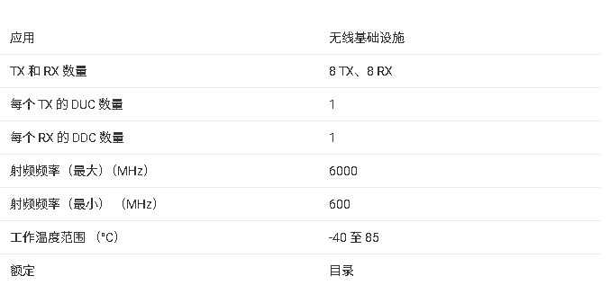
AFE8092 8 个发射、8 个接收 RF 采样收发器技术手册
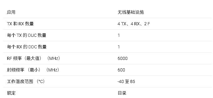
AFE7769 4 个发射、4 个接收、2 个反馈射频收发器


评论