 如何测试红外传感器以确保其正常工作

概述
在说CdS光电管之间有一些区别:
IR检测器经过特殊过滤以用于红外光,它们不擅长检测可见光。另一方面,光电管擅长检测黄/绿可见光,而不擅长红外光
红外检测器内部有一个解调器,用于寻找38 KHz的调制IR。只是无法检测到红外LED发光,它必须以38KHz的PWM频率闪烁。光电管没有任何类型的解调器,可以检测到光电管响应速度(大约1KHz)内的任何频率(包括DC)。
红外检测器是数字输出的-它们可以检测38KHz红外信号,输出低电平(0V)或它们没有检测到并输出高电平(5V)。光电管就像电阻一样,电阻会根据它们所暴露的光量而变化
在本教程中,我们将展示如何
测试红外传感器以确保其正常工作
将原始IR代码读入微控制器
创建相机间隔计
从微控制器上的遥控器收听“命令”
某些统计信息
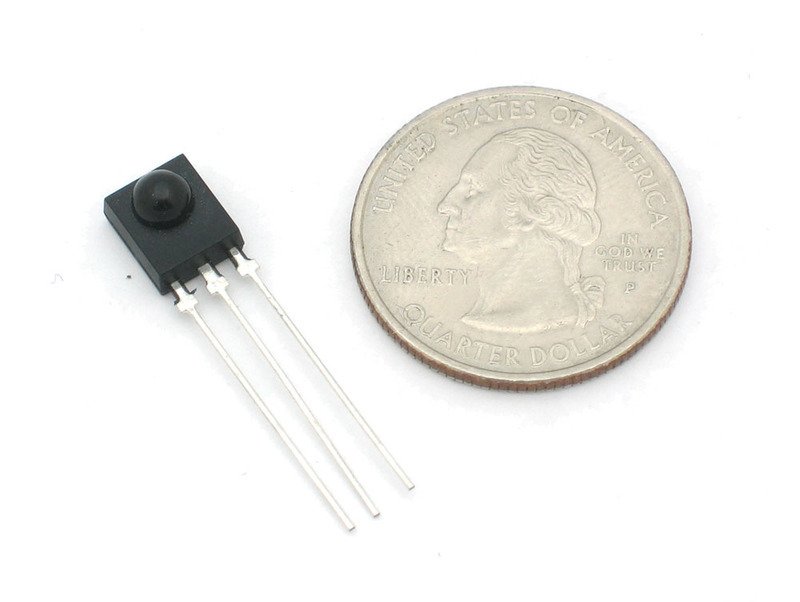
这些统计信息适用于Adafruit商店(也称为PNA4602)中的红外探测器。几乎所有光电管的规格都略有不同,尽管它们的工作原理几乎相同。如果有数据表,您将需要参考它
尺寸:正方形,探测器面积7mm x 8mm
输出:检测到38KHz载波时为0V(低),否则为5V(高)
灵敏度范围::800nm至1100nm,峰值响应在940nm。频率范围为35KHz至41KHz,峰值检测频率为38KHz
电源: 3-5V DC 3mA
PNA4602数据表( (现已停产)或 GP1UX311QS 或 TSOP38238 (与引脚兼容的替代品)
您可以测量的内容
从这些数据表图表中可以看到,峰值频率检测在 38 KHz ,峰值LED颜色为 940 nm 。您可以使用大约35 KHz至41 KHz的频率,但灵敏度会下降,因此远距离也无法检测到。同样,您可以使用850至1100 nm的LED,但它们不能与900至1000nm的LED一样工作,因此请确保获得匹配的LED!
尝试获取940nm-记住940nm不是可见光(它的红外光)!
测试IR传感器
由于传感器内部有半导体/芯片,因此必须使用3-5V的电源才能正常工作。将其与光电池和FSR进行对比,它们像电阻一样发挥作用,因此可以用万用表简单地进行测试。

在这里,我们将按以下方式连接检测器:
Pin 1是输出,因此我们将其接线连接到可见的LED和电阻器
引脚2接地
引脚3为VCC,连接到3-5V
当检测器看到IR时信号,它将拉低输出,从而打开LED指示灯-由于LED指示灯为红色,因此我们比IR更容易看到它!
我们将使用4节3号1.3V电池(我使用NiMH),以便为传感器供电大约4V。
2个电池(3V)可能太少。如果您有三节AA电池座,则3块电池应该没问题
如果周围有一个电池,也可以从Arduino等微控制器获得5V电压。接地连接到中间引脚。
红色LED的正(较长)头连接到+ 6V引脚,负(较短引线)通过200到1000欧姆的电阻连接到第一个引脚。
现在抓住电视,DVD,计算机等遥控器,将其指向检测器,同时按下一些按钮,每当遥控器发出信号时,LED应该会闪烁两次按下。
红外遥控信号
现在我们知道传感器可以正常工作了,我们想弄清楚发送的是什么吗?但是在执行此操作之前,我们首先要仔细检查数据是如何从红外遥控器(在您的手中)发送到红外接收传感器(在面包板上)的
在此示例中,我们将使用索尼电源/off来自Sony电视遥控器的IR代码。它非常简单,并且经常记录在案!
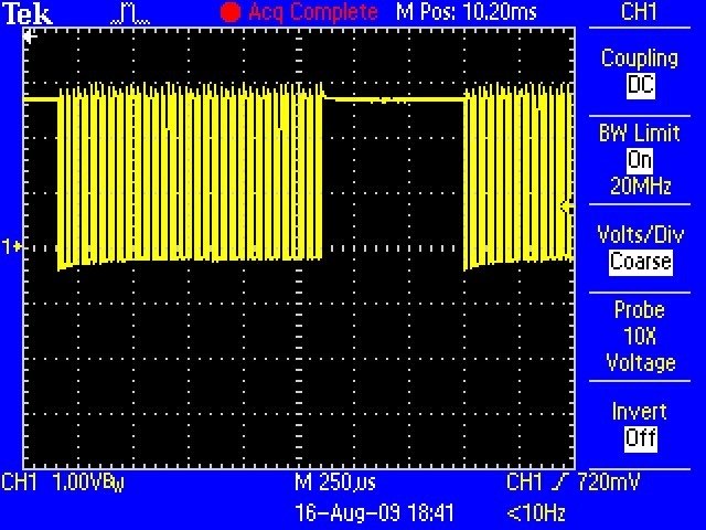
假设我们有一个Sony遥控器,我们可以确切地查看从IR LED发射出的光。我们将连接一个基本的光传感器(如基本的光电管!)并进行监听。我们不会使用像PNA4602这样的解码器(到目前为止),因为我们希望看到未解码的信号。我们看到的是以下内容:

基本上我们看到脉冲或IR信号。黄色的“块”表示IR LED处于传输状态,而只有一条线时,IR LED处于熄灭状态。 (请注意,处于3VDC的电压仅仅是由于我连接传感器的方式,如果我将上拉交换为下拉,则它将在地面。)
第一个“块”大约是2.5毫秒长(请参见侧面的光标和测量值)
如果您放大这些块之一……
您会发现它们并不是真正的“障碍”,而是非常快的脉冲! p》
如果一直放大…
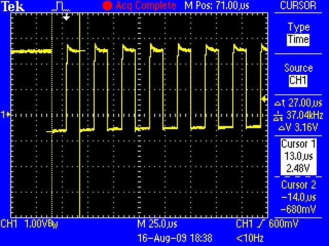
您可以测量IR脉冲的频率。正如您可以从光标和侧面的测量值看出的那样,频率大约为37.04KHz
OK,因此现在我们可以了解如何发送IR代码了。红外发射器LED迅速以38KHz的高频率脉冲化(PWM-脉宽调制),然后该PWM同样被慢速地脉冲化开和关,时间约为1-3 ms。
为什么不只打开和关闭LED?为什么会有PWM“载波”脉冲?原因很多!
一个原因是,这会使LED冷却。红外LED最多可消耗1 A(1000毫安!)的电流。大多数LED仅占用20mA左右。这意味着IR LED是为大功率喷砂而设计的,但它们只能承受几微秒的时间。通过PWM‘ing,可以让LED冷却一半的时间
另一个原因是电视将仅收听特定频率的PWM。因此,在37KHz的Sony遥控器上无法使用仅要求50KHz的JVC DVD播放器。
最后,最重要的原因是通过对载波施加脉冲,可以减少环境照明的影响。电视只寻找时钟频率约为37KHz的亮度变化。就像对我们来说分辨音频音调之间的差异比确定音调的精确音高(至少对大多数人而言)一样容易
好,所以现在我们知道了载波频率。其37KHz。接下来让我们找到脉冲宽度!
回头看第一张示波器图片
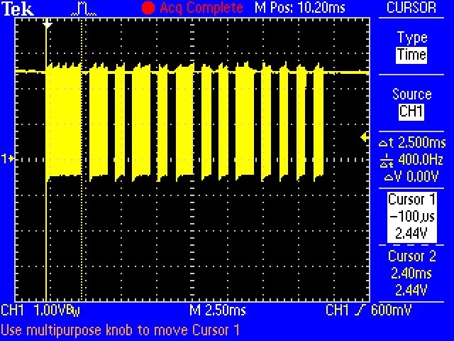
第一个脉冲为2.5毫秒。我们可以使用光标来测量剩余的脉冲。我将为您保留12张图像,让您知道脉冲是:
PWM ON 关闭
2.4毫秒0.6毫秒
1.2 ms0.6 ms
0.6 ms0.6 ms
1.2 ms0.6 ms
0.6 ms0.6 ms
1.2 ms0.6 ms
0.6 ms0.6 ms
0.6毫秒0.6毫秒
1.2毫秒0.6毫秒
0.6毫秒0.6毫秒
0.6毫秒0.6毫秒
0.6毫秒0.6毫秒
0.6毫秒270毫秒
因此,假设您没有价格为$ 1000的示波器,您还能如何读取这些信号?像PNA4602这样的IR解码器很好地帮了我们一个忙,它“滤出”了38KHz信号,因此我们只能得到毫粘范围内的大信号块。对于微控制器来说,这要容易得多。那就是我们在下一节中要做的!
使用红外传感器
好消息是,连接此传感器非常容易。只需将输出连接到数字引脚即可。坏消息是,Arduino的友好的 digitalRead()程序太慢了,无法可靠地读取快速信号,因此我们直接从引脚D2使用硬件引脚读取功能,这就是行“ IRpin_PIN&BV(IRpin))”。此技巧特定于基于ATmega328的板,例如Arduino Uno,Adafruit Metro等。

完全组装的Adafruit METRO 328-兼容Arduino IDE
产品ID:50
我们肯定喜欢Adafruit的ATmega328,并且将lota用于我们自己的项目。该处理器具有大量的GPIO,模拟输入,硬件UART SPI和I2C,。。.
$ 17.50
入库
添加到购物车
下载:Project Zip 或 ir_codes。 ino | 在Github上查看
复制代码
/* Raw IR decoder sketch!
This sketch/program uses the Arduno and a PNA4602 to
decode IR received. This can be used to make a IR receiver
(by looking for a particular code)
or transmitter (by pulsing an IR LED at ~38KHz for the
durations detected
Code is public domain, check out www.ladyada.net and adafruit.com
for more tutorials!
*/
// We need to use the ’raw‘ pin reading methods
// because timing is very important here and the digitalRead()
// procedure is slower!
//uint8_t IRpin = 2;
// Digital pin #2 is the same as Pin D2 see
// http://arduino.cc/en/Hacking/PinMapping168 for the ’raw‘ pin mapping
#define IRpin_PIN PIND
#define IRpin 2
// the maximum pulse we’ll listen for - 65 milliseconds is a long time
#define MAXPULSE 65000
// what our timing resolution should be, larger is better
// as its more ‘precise’ - but too large and you wont get
// accurate timing
#define RESOLUTION 20
// we will store up to 100 pulse pairs (this is -a lot-)
uint16_t pulses[100][2]; // pair is high and low pulse
uint8_t currentpulse = 0; // index for pulses we‘re storing
void setup(void) {
Serial.begin(9600);
Serial.println(“Ready to decode IR!”);
}
void loop(void) {
uint16_t highpulse, lowpulse; // temporary storage timing
highpulse = lowpulse = 0; // start out with no pulse length
// while (digitalRead(IRpin)) { // this is too slow!
while (IRpin_PIN & (1 《《 IRpin)) {
// pin is still HIGH
// count off another few microseconds
highpulse++;
delayMicroseconds(RESOLUTION);
// If the pulse is too long, we ’timed out‘ - either nothing
// was received or the code is finished, so print what
// we’ve grabbed so far, and then reset
if ((highpulse 》= MAXPULSE) && (currentpulse != 0)) {
printpulses();
currentpulse=0;
return;
}
}
// we didn‘t time out so lets stash the reading
pulses[currentpulse][0] = highpulse;
// same as above
while (! (IRpin_PIN & _BV(IRpin))) {
// pin is still LOW
lowpulse++;
delayMicroseconds(RESOLUTION);
if ((lowpulse 》= MAXPULSE) && (currentpulse != 0)) {
printpulses();
currentpulse=0;
return;
}
}
pulses[currentpulse][1] = lowpulse;
// we read one high-low pulse successfully, continue!
currentpulse++;
}
void printpulses(void) {
Serial.println(“ Received: OFF ON”);
for (uint8_t i = 0; i 《 currentpulse; i++) {
Serial.print(pulses[i][0] * RESOLUTION, DEC);
Serial.print(“ usec, ”);
Serial.print(pulses[i][1] * RESOLUTION, DEC);
Serial.println(“ usec”);
}
// print it in a ’array‘ format
Serial.println(“int IRsignal[] = {”);
Serial.println(“// ON, OFF ”);
for (uint8_t i = 0; i 《 currentpulse-1; i++) {
//Serial.print(“ ”); // tab
Serial.print(“pulseIR(”);
Serial.print(pulses[i][1] * RESOLUTION , DEC);
Serial.print(“);”);
Serial.println(“”);
//Serial.print(“ ”);
Serial.print(“delayMicroseconds(”);
Serial.print(pulses[i+1][0] * RESOLUTION , DEC);
Serial.println(“);”);
}
//Serial.print(“ ”); // tab
Serial.print(“pulseIR(”);
Serial.print(pulses[currentpulse-1][1] * RESOLUTION, DEC);
Serial.print(“);”);
}
如果您在指向Sony IR遥控器并按下ON按钮的同时运行此程序,则会得到以下内容。。.
如果您忽略第一个OFF脉冲(这只是从Arduino开始的时间打开第一个接收到的IR信号)和最后一个打开脉冲(即下一个代码的开始),您会找到Sony电源代码:
PWM开启关闭
2.5 ms0.6毫秒
1.2 ms0.6 ms
0.6 ms0.6 ms
1.2 ms0.6 ms
0.6 ms0.6 ms
1.2 ms0.6 ms
0.6 ms0.6 ms
0.6 ms0.6 ms
1.2 ms0.6 ms
0.6 ms0.6 ms
0.6 ms0.6 ms
0.6毫秒0.6毫秒
0.6毫秒27.2毫秒
现在,我们可以读取红外代码了,制作一个间隔计
好,让我们做一个基础项目。我们要做的第一个是制作一个间隔计。间隔计基本上是一种电子设备,可使照相机每隔几分钟左右关闭一次。这可以用于游戏中时光倒流项目或风筝摄影或其他照片项目。
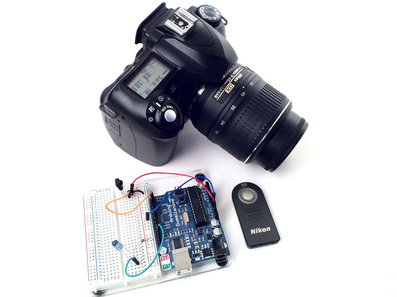
我们将要使用的相机具有一个红外遥控器,您可以将其关闭(大多数高端相机都有)。

首先我们要弄清楚通过读取按下按钮时发送的信号来读出代码。然后,我们将获取这些数据,并使Arduino每分钟一次将该代码输出到IR LED中。
好,第一步很简单,将遥控器对准IR传感器,然后按一下按钮,我们得到了
看起来像发送的数据是:
PWM ON OFF
2.0 ms27 ms
0.4 ms1.5 ms
0.5 ms3.5 ms
0.5 ms62.2毫秒
2.0毫秒27毫秒
0.5毫秒1.5毫秒
0.5毫秒3.5毫秒
0.5 ms
如果仔细观察,您会发现它实际上只是
PWM ON OFF
2.0 ms27 ms
0.4毫秒1.5毫秒
0.5毫秒3.5毫秒
0.5毫秒62.2毫秒
已发送两次。两次发送相同的信号是很常见的-加倍以确保收到信号
下一步,我们需要将940nm IR LED连接到Arduino的输出

然后我们将写一个草图
下载: Project Zip 或 intervalometer.ino | 在Github上查看
复制代码
// This sketch will send out a Nikon D50 trigger signal (probably works with most Nikons)
// See the full tutorial at https://learn.adafruit.com/ir-sensor/making-an-intervalometer
// MIT License, attribution appreciated Limor Fried, Adafruit Industries
int IRledPin = 13; // LED connected to digital pin 13
// The setup() method runs once, when the sketch starts
void setup() {
// initialize the IR digital pin as an output:
pinMode(IRledPin, OUTPUT);
Serial.begin(9600);
}
void loop()
{
Serial.println(“Sending IR signal”);
SendNikonCode();
delay(60*1000); // wait one minute (60 seconds * 1000 milliseconds)
}
// This procedure sends a 38KHz pulse to the IRledPin
// for a certain # of microseconds. We’ll use this whenever we need to send codes
void pulseIR(long microsecs) {
// we‘ll count down from the number of microseconds we are told to wait
cli(); // this turns off any background interrupts
while (microsecs 》 0) {
// 38 kHz is about 13 microseconds high and 13 microseconds low
digitalWrite(IRledPin, HIGH); // this takes about 3 microseconds to happen
delayMicroseconds(10); // hang out for 10 microseconds, you can also change this to 9 if its not working
digitalWrite(IRledPin, LOW); // this also takes about 3 microseconds
delayMicroseconds(10); // hang out for 10 microseconds, you can also change this to 9 if its not working
// so 26 microseconds altogether
microsecs -= 26;
}
sei(); // this turns them back on
}
void SendNikonCode() {
// This is the code for my particular Nikon, for others use the tutorial
// to ’grab‘ the proper code from the remote
pulseIR(2080);
delay(27);
pulseIR(440);
delayMicroseconds(1500);
pulseIR(460);
delayMicroseconds(3440);
pulseIR(480);
delay(65); // wait 65 milliseconds before sending it again
pulseIR(2000);
delay(27);
pulseIR(440);
delayMicroseconds(1500);
pulseIR(460);
delayMicroseconds(3440);
pulseIR(480);
}
void pulseIR(long microsecs)是我们的帮助程序,它将像之前看到的那样创建PWM IR信号。我使用示波器进行了微调,以使延迟加起来正确。我们使用不常讨论的cli()和sei()过程关闭中断。 Arduino在后台执行了一些操作,例如寻找要读取或写入的串行数据,跟踪时间等。大多数情况下,我们可以忽略它,但是对于像这样的微妙的高速信号,我们希望保持安静,以便我们会得到一个很好的干净信号
如果您查看SendNikonCode(),您将看到我们在上一个项目中通过对来自红外传感器的脉冲进行计时推导出的IR命令代码。

并且效果很好,请确保将IR LED正确对准相机。
读取IR命令
对于我们的最终项目,我们将使用遥控器将消息发送到微控制器。例如,这对于可以用IR遥控器控制的机器人可能很有用。这对于想要在远处无需电线控制的项目也可能是好的。您可以使用任何所需的遥控器,也可以从毫无戒心的行家那里窃取其中之一。

我们将使用之前草图中的代码进行原始红外读取,但是这次我们将编辑打印机的外部它为我们提供了C数组中的脉冲,这将使我们更易于用于模式匹配。
下载:文件
复制代码
void printpulses(void) {
Serial.println(“ Received: OFF ON”);
for (uint8_t i = 0; i 《 currentpulse; i++) {
Serial.print(pulses[i][0] * RESOLUTION, DEC);
Serial.print(“ usec, ”);
Serial.print(pulses[i][1] * RESOLUTION, DEC);
Serial.println(“ usec”);
}
// print it in a ’array‘ format
Serial.println(“int IRsignal[] = {”);
Serial.println(“// ON, OFF (in 10’s of microseconds)”);
for (uint8_t i = 0; i 《 currentpulse-1; i++) {
Serial.print(“ ”); // tab
Serial.print(pulses[i][1] * RESOLUTION / 10, DEC);
Serial.print(“, ”);
Serial.print(pulses[i+1][0] * RESOLUTION / 10, DEC);
Serial.println(“,”);
}
Serial.print(“ ”); // tab
Serial.print(pulses[currentpulse-1][1] * RESOLUTION / 10, DEC);
Serial.print(“, 0};”);
} void printpulses(void) {
Serial.println(“ Received: OFF ON”);
for (uint8_t i = 0; i 《 currentpulse; i++) {
Serial.print(pulses[i][0] * RESOLUTION, DEC);
Serial.print(“ usec, ”);
Serial.print(pulses[i][1] * RESOLUTION, DEC);
Serial.println(“ usec”);
}
// print it in a ‘array’ format
Serial.println(“int IRsignal[] = {”);
Serial.println(“// ON, OFF (in 10‘s of microseconds)”);
for (uint8_t i = 0; i 《 currentpulse-1; i++) {
Serial.print(“ ”); // tab
Serial.print(pulses[i][1] * RESOLUTION / 10, DEC);
Serial.print(“, ”);
Serial.print(pulses[i+1][0] * RESOLUTION / 10, DEC);
Serial.println(“,”);
}
Serial.print(“ ”); // tab
Serial.print(pulses[currentpulse-1][1] * RESOLUTION / 10, DEC);
Serial.print(“, 0};”);
}
我上传了新草图,并按了 Play Apple遥控器上的按钮并获得以下内容:
下载:文件
复制代码
int IRsignal[] = { // ON, OFF (in 10’s of microseconds)
912, 438,
68, 48,
68, 158,
68, 158,
68, 158,
68, 48,
68, 158,
68, 158,
68, 158,
70, 156,
70, 158,
68, 158,
68, 48,
68, 46,
70, 46,
68, 46,
68, 160,
68, 158,
70, 46,
68, 158,
68, 46,
70, 46,
68, 48,
68, 46,
68, 48,
66, 48,
68, 48,
66, 160,
66, 50,
66, 160,
66, 52,
64, 160,
66, 48,
66, 3950,
908, 214,
66, 3012,
908, 212,
68, 0}; int IRsignal[] = { // ON, OFF (in 10‘s of microseconds)
912, 438,
68, 48,
68, 158,
68, 158,
68, 158,
68, 48,
68, 158,
68, 158,
68, 158,
70, 156,
70, 158,
68, 158,
68, 48,
68, 46,
70, 46,
68, 46,
68, 160,
68, 158,
70, 46,
68, 158,
68, 46,
70, 46,
68, 48,
68, 46,
68, 48,
66, 48,
68, 48,
66, 160,
66, 50,
66, 160,
66, 52,
64, 160,
66, 48,
66, 3950,
908, 214,
66, 3012,
908, 212,
68, 0};
我们将尝试检测该代码。
让我们开始一个名为 IR Commander的新草图(您可以从GitHub下方的绿色按钮下载最终代码,或在完整的代码列表中单击Download Project Zip)。
打开此页面上代码的GitHub存储库
下载:Project Zip 或 ircommander.ino | 在Github上查看
复制代码
/* Raw IR commander
This sketch/program uses the Arduno and a PNA4602 to
decode IR received. It then attempts to match it to a previously
recorded IR signal. Limor Fried, Adafruit Industries
MIT License, please attribute
check out learn.adafruit.com for more tutorials!
*/
// We need to use the ’raw‘ pin reading methods
// because timing is very important here and the digitalRead()
// procedure is slower!
//uint8_t IRpin = 2;
// Digital pin #2 is the same as Pin D2 see
// http://arduino.cc/en/Hacking/PinMapping168 for the ’raw‘ pin mapping
#define IRpin_PIN PIND
#define IRpin 2
// the maximum pulse we’ll listen for - 65 milliseconds is a long time
#define MAXPULSE 65000
#define NUMPULSES 50
// what our timing resolution should be, larger is better
// as its more ‘precise’ - but too large and you wont get
// accurate timing
#define RESOLUTION 20
// What percent we will allow in variation to match the same code
#define FUZZINESS 20
// we will store up to 100 pulse pairs (this is -a lot-)
uint16_t pulses[NUMPULSES][2]; // pair is high and low pulse
uint8_t currentpulse = 0; // index for pulses we‘re storing
#include “ircommander.h”
void setup(void) {
Serial.begin(9600);
Serial.println(“Ready to decode IR!”);
}
void loop(void) {
int numberpulses;
numberpulses = listenForIR();
Serial.print(“Heard ”);
Serial.print(numberpulses);
Serial.println(“-pulse long IR signal”);
if (IRcompare(numberpulses, ApplePlaySignal,sizeof(ApplePlaySignal)/4)) {
Serial.println(“PLAY”);
}
if (IRcompare(numberpulses, AppleRewindSignal,sizeof(AppleRewindSignal)/4)) {
Serial.println(“REWIND”);
}
if (IRcompare(numberpulses, AppleForwardSignal,sizeof(AppleForwardSignal)/4)) {
Serial.println(“FORWARD”);
}
delay(500);
}
//KGO: added size of compare sample. Only compare the minimum of the two
boolean IRcompare(int numpulses, int Signal[], int refsize) {
int count = min(numpulses,refsize);
Serial.print(“count set to: ”);
Serial.println(count);
for (int i=0; i《 count-1; i++) {
int oncode = pulses[i][1] * RESOLUTION / 10;
int offcode = pulses[i+1][0] * RESOLUTION / 10;
#ifdef DEBUG
Serial.print(oncode); // the ON signal we heard
Serial.print(“ - ”);
Serial.print(Signal[i*2 + 0]); // the ON signal we want
#endif
// check to make sure the error is less than FUZZINESS percent
if ( abs(oncode - Signal[i*2 + 0]) 《= (Signal[i*2 + 0] * FUZZINESS / 100)) {
#ifdef DEBUG
Serial.print(“ (ok)”);
#endif
} else {
#ifdef DEBUG
Serial.print(“ (x)”);
#endif
// we didn’t match perfectly, return a false match
return false;
}
#ifdef DEBUG
Serial.print(“ ”); // tab
Serial.print(offcode); // the OFF signal we heard
Serial.print(“ - ”);
Serial.print(Signal[i*2 + 1]); // the OFF signal we want
#endif
if ( abs(offcode - Signal[i*2 + 1]) 《= (Signal[i*2 + 1] * FUZZINESS / 100)) {
#ifdef DEBUG
Serial.print(“ (ok)”);
#endif
} else {
#ifdef DEBUG
Serial.print(“ (x)”);
#endif
// we didn‘t match perfectly, return a false match
return false;
}
#ifdef DEBUG
Serial.println();
#endif
}
// Everything matched!
return true;
}
int listenForIR(void) {
currentpulse = 0;
while (1) {
uint16_t highpulse, lowpulse; // temporary storage timing
highpulse = lowpulse = 0; // start out with no pulse length
// while (digitalRead(IRpin)) { // this is too slow!
while (IRpin_PIN & (1 《《 IRpin)) {
// pin is still HIGH
// count off another few microseconds
highpulse++;
delayMicroseconds(RESOLUTION);
// If the pulse is too long, we ’timed out‘ - either nothing
// was received or the code is finished, so print what
// we’ve grabbed so far, and then reset
// KGO: Added check for end of receive buffer
if (((highpulse 》= MAXPULSE) && (currentpulse != 0))|| currentpulse == NUMPULSES) {
return currentpulse;
}
}
// we didn‘t time out so lets stash the reading
pulses[currentpulse][0] = highpulse;
// same as above
while (! (IRpin_PIN & _BV(IRpin))) {
// pin is still LOW
lowpulse++;
delayMicroseconds(RESOLUTION);
// KGO: Added check for end of receive buffer
if (((lowpulse 》= MAXPULSE) && (currentpulse != 0))|| currentpulse == NUMPULSES) {
return currentpulse;
}
}
pulses[currentpulse][1] = lowpulse;
// we read one high-low pulse successfully, continue!
currentpulse++;
}
}
void printpulses(void) {
Serial.println(“ Received: OFF ON”);
for (uint8_t i = 0; i 《 currentpulse; i++) {
Serial.print(pulses[i][0] * RESOLUTION, DEC);
Serial.print(“ usec, ”);
Serial.print(pulses[i][1] * RESOLUTION, DEC);
Serial.println(“ usec”);
}
// print it in a ’array‘ format
Serial.println(“int IRsignal[] = {”);
Serial.println(“// ON, OFF (in 10’s of microseconds)”);
for (uint8_t i = 0; i 《 currentpulse-1; i++) {
Serial.print(“ ”); // tab
Serial.print(pulses[i][1] * RESOLUTION / 10, DEC);
Serial.print(“, ”);
Serial.print(pulses[i+1][0] * RESOLUTION / 10, DEC);
Serial.println(“,”);
}
Serial.print(“ ”); // tab
Serial.print(pulses[currentpulse-1][1] * RESOLUTION / 10, DEC);
Serial.print(“, 0};”);
}
/* Raw IR commander
This sketch/program uses the Arduno and a PNA4602 to
decode IR received. It then attempts to match it to a previously
recorded IR signal. Limor Fried, Adafruit Industries
MIT License, please attribute
check out learn.adafruit.com for more tutorials!
*/
// We need to use the ‘raw’ pin reading methods
// because timing is very important here and the digitalRead()
// procedure is slower!
//uint8_t IRpin = 2;
// Digital pin #2 is the same as Pin D2 see
// http://arduino.cc/en/Hacking/PinMapping168 for the ‘raw’ pin mapping
#define IRpin_PIN PIND
#define IRpin 2
// the maximum pulse we‘ll listen for - 65 milliseconds is a long time
#define MAXPULSE 65000
#define NUMPULSES 50
// what our timing resolution should be, larger is better
// as its more ’precise‘ - but too large and you wont get
// accurate timing
#define RESOLUTION 20
// What percent we will allow in variation to match the same code
#define FUZZINESS 20
// we will store up to 100 pulse pairs (this is -a lot-)
uint16_t pulses[NUMPULSES][2]; // pair is high and low pulse
uint8_t currentpulse = 0; // index for pulses we’re storing
#include “ircommander.h”
void setup(void) {
Serial.begin(9600);
Serial.println(“Ready to decode IR!”);
}
void loop(void) {
int numberpulses;
numberpulses = listenForIR();
Serial.print(“Heard ”);
Serial.print(numberpulses);
Serial.println(“-pulse long IR signal”);
if (IRcompare(numberpulses, ApplePlaySignal,sizeof(ApplePlaySignal)/4)) {
Serial.println(“PLAY”);
}
if (IRcompare(numberpulses, AppleRewindSignal,sizeof(AppleRewindSignal)/4)) {
Serial.println(“REWIND”);
}
if (IRcompare(numberpulses, AppleForwardSignal,sizeof(AppleForwardSignal)/4)) {
Serial.println(“FORWARD”);
}
delay(500);
}
//KGO: added size of compare sample. Only compare the minimum of the two
boolean IRcompare(int numpulses, int Signal[], int refsize) {
int count = min(numpulses,refsize);
Serial.print(“count set to: ”);
Serial.println(count);
for (int i=0; i《 count-1; i++) {
int oncode = pulses[i][1] * RESOLUTION / 10;
int offcode = pulses[i+1][0] * RESOLUTION / 10;
#ifdef DEBUG
Serial.print(oncode); // the ON signal we heard
Serial.print(“ - ”);
Serial.print(Signal[i*2 + 0]); // the ON signal we want
#endif
// check to make sure the error is less than FUZZINESS percent
if ( abs(oncode - Signal[i*2 + 0]) 《= (Signal[i*2 + 0] * FUZZINESS / 100)) {
#ifdef DEBUG
Serial.print(“ (ok)”);
#endif
} else {
#ifdef DEBUG
Serial.print(“ (x)”);
#endif
// we didn‘t match perfectly, return a false match
return false;
}
#ifdef DEBUG
Serial.print(“ ”); // tab
Serial.print(offcode); // the OFF signal we heard
Serial.print(“ - ”);
Serial.print(Signal[i*2 + 1]); // the OFF signal we want
#endif
if ( abs(offcode - Signal[i*2 + 1]) 《= (Signal[i*2 + 1] * FUZZINESS / 100)) {
#ifdef DEBUG
Serial.print(“ (ok)”);
#endif
} else {
#ifdef DEBUG
Serial.print(“ (x)”);
#endif
// we didn’t match perfectly, return a false match
return false;
}
#ifdef DEBUG
Serial.println();
#endif
}
// Everything matched!
return true;
}
int listenForIR(void) {
currentpulse = 0;
while (1) {
uint16_t highpulse, lowpulse; // temporary storage timing
highpulse = lowpulse = 0; // start out with no pulse length
// while (digitalRead(IRpin)) { // this is too slow!
while (IRpin_PIN & (1 《《 IRpin)) {
// pin is still HIGH
// count off another few microseconds
highpulse++;
delayMicroseconds(RESOLUTION);
// If the pulse is too long, we ‘timed out’ - either nothing
// was received or the code is finished, so print what
// we‘ve grabbed so far, and then reset
// KGO: Added check for end of receive buffer
if (((highpulse 》= MAXPULSE) && (currentpulse != 0))|| currentpulse == NUMPULSES) {
return currentpulse;
}
}
// we didn’t time out so lets stash the reading
pulses[currentpulse][0] = highpulse;
// same as above
while (! (IRpin_PIN & _BV(IRpin))) {
// pin is still LOW
lowpulse++;
delayMicroseconds(RESOLUTION);
// KGO: Added check for end of receive buffer
if (((lowpulse 》= MAXPULSE) && (currentpulse != 0))|| currentpulse == NUMPULSES) {
return currentpulse;
}
}
pulses[currentpulse][1] = lowpulse;
// we read one high-low pulse successfully, continue!
currentpulse++;
}
}
void printpulses(void) {
Serial.println(“ Received: OFF ON”);
for (uint8_t i = 0; i 《 currentpulse; i++) {
Serial.print(pulses[i][0] * RESOLUTION, DEC);
Serial.print(“ usec, ”);
Serial.print(pulses[i][1] * RESOLUTION, DEC);
Serial.println(“ usec”);
}
// print it in a ‘array’ format
Serial.println(“int IRsignal[] = {”);
Serial.println(“// ON, OFF (in 10‘s of microseconds)”);
for (uint8_t i = 0; i 《 currentpulse-1; i++) {
Serial.print(“ ”); // tab
Serial.print(pulses[i][1] * RESOLUTION / 10, DEC);
Serial.print(“, ”);
Serial.print(pulses[i+1][0] * RESOLUTION / 10, DEC);
Serial.println(“,”);
}
Serial.print(“ ”); // tab
Serial.print(pulses[currentpulse-1][1] * RESOLUTION / 10, DEC);
Serial.print(“, 0};”);
}
下载:Project Zip 或 ircommander .h | 在Github上查看
复制代码
/******************* our codes ************/
int ApplePlaySignal[] = {
// ON, OFF (in 10’s of microseconds)
912, 438,
68, 48,
68, 158,
68, 158,
68, 158,
68, 48,
68, 158,
68, 158,
68, 158,
70, 156,
70, 158,
68, 158,
68, 48,
68, 46,
70, 46,
68, 46,
68, 160,
68, 158,
70, 46,
68, 158,
68, 46,
70, 46,
68, 48,
68, 46,
68, 48,
66, 48,
68, 48,
66, 160,
66, 50,
66, 160,
66, 50,
64, 160,
66, 50,
66, 3950,
908, 214,
66, 3012,
908, 212,
68, 0};
int AppleForwardSignal[] = {
// ON, OFF (in 10‘s of microseconds)
908, 444,
64, 50,
66, 162,
64, 162,
64, 162,
64, 52,
64, 162,
64, 162,
64, 162,
64, 164,
62, 164,
64, 162,
64, 52,
62, 52,
64, 52,
64, 50,
64, 164,
64, 50,
64, 164,
64, 162,
64, 50,
66, 50,
66, 50,
64, 50,
66, 50,
64, 52,
64, 50,
66, 160,
66, 50,
64, 162,
66, 50,
64, 162,
64, 50,
66, 3938,
906, 214,
66, 3014,
906, 214,
64, 0};
int AppleRewindSignal[] = {
// ON, OFF (in 10’s of microseconds)
908, 442,
66, 48,
66, 162,
66, 160,
66, 160,
66, 50,
66, 160,
66, 160,
66, 160,
68, 158,
68, 160,
66, 160,
66, 50,
66, 48,
66, 50,
66, 48,
66, 162,
66, 160,
66, 48,
68, 48,
66, 160,
66, 50,
66, 50,
66, 48,
66, 50,
66, 48,
68, 48,
66, 160,
66, 50,
66, 160,
66, 50,
66, 160,
66, 48,
68, 3936,
906, 214,
66, 0};
/******************* our codes ************/
int ApplePlaySignal[] = {
// ON, OFF (in 10‘s of microseconds)
912, 438,
68, 48,
68, 158,
68, 158,
68, 158,
68, 48,
68, 158,
68, 158,
68, 158,
70, 156,
70, 158,
68, 158,
68, 48,
68, 46,
70, 46,
68, 46,
68, 160,
68, 158,
70, 46,
68, 158,
68, 46,
70, 46,
68, 48,
68, 46,
68, 48,
66, 48,
68, 48,
66, 160,
66, 50,
66, 160,
66, 50,
64, 160,
66, 50,
66, 3950,
908, 214,
66, 3012,
908, 212,
68, 0};
int AppleForwardSignal[] = {
// ON, OFF (in 10’s of microseconds)
908, 444,
64, 50,
66, 162,
64, 162,
64, 162,
64, 52,
64, 162,
64, 162,
64, 162,
64, 164,
62, 164,
64, 162,
64, 52,
62, 52,
64, 52,
64, 50,
64, 164,
64, 50,
64, 164,
64, 162,
64, 50,
66, 50,
66, 50,
64, 50,
66, 50,
64, 52,
64, 50,
66, 160,
66, 50,
64, 162,
66, 50,
64, 162,
64, 50,
66, 3938,
906, 214,
66, 3014,
906, 214,
64, 0};
int AppleRewindSignal[] = {
// ON, OFF (in 10‘s of microseconds)
908, 442,
66, 48,
66, 162,
66, 160,
66, 160,
66, 50,
66, 160,
66, 160,
66, 160,
68, 158,
68, 160,
66, 160,
66, 50,
66, 48,
66, 50,
66, 48,
66, 162,
66, 160,
66, 48,
68, 48,
66, 160,
66, 50,
66, 50,
66, 48,
66, 50,
66, 48,
68, 48,
66, 160,
66, 50,
66, 160,
66, 50,
66, 160,
66, 48,
68, 3936,
906, 214,
66, 0};
此代码使用了先前草图的一部分。我们要做的第一部分是创建一个函数,该函数只侦听IR代码,并将脉冲时序放入 pulses [] 数组中。它将返回它听到的脉冲数作为返回值。
下载:文件
复制代码
int listenForIR(void) {
currentpulse = 0;
while (1) {
uint16_t highpulse, lowpulse; // temporary storage timing
highpulse = lowpulse = 0; // start out with no pulse length
// while (digitalRead(IRpin)) { // this is too slow!
while (IRpin_PIN & (1 《《 IRpin)) {
// pin is still HIGH
// count off another few microseconds
highpulse++;
delayMicroseconds(RESOLUTION);
// If the pulse is too long, we ’timed out‘ - either nothing
// was received or the code is finished, so print what
// we’ve grabbed so far, and then reset
if ((highpulse 》= MAXPULSE) && (currentpulse != 0)) {
return currentpulse;
}
}
// we didn‘t time out so lets stash the reading
pulses[currentpulse][0] = highpulse;
// same as above
while (! (IRpin_PIN & _BV(IRpin))) {
// pin is still LOW
lowpulse++;
delayMicroseconds(RESOLUTION);
if ((lowpulse 》= MAXPULSE) && (currentpulse != 0)) {
return currentpulse;
}
}
pulses[currentpulse][1] = lowpulse;
// we read one high-low pulse successfully, continue!
currentpulse++;
}
} int listenForIR(void) {
currentpulse = 0;
while (1) {
uint16_t highpulse, lowpulse; // temporary storage timing
highpulse = lowpulse = 0; // start out with no pulse length
// while (digitalRead(IRpin)) { // this is too slow!
while (IRpin_PIN & (1 《《 IRpin)) {
// pin is still HIGH
// count off another few microseconds
highpulse++;
delayMicroseconds(RESOLUTION);
// If the pulse is too long, we ’timed out‘ - either nothing
// was received or the code is finished, so print what
// we’ve grabbed so far, and then reset
if ((highpulse 》= MAXPULSE) && (currentpulse != 0)) {
return currentpulse;
}
}
// we didn‘t time out so lets stash the reading
pulses[currentpulse][0] = highpulse;
// same as above
while (! (IRpin_PIN & _BV(IRpin))) {
// pin is still LOW
lowpulse++;
delayMicroseconds(RESOLUTION);
if ((lowpulse 》= MAXPULSE) && (currentpulse != 0)) {
return currentpulse;
}
}
pulses[currentpulse][1] = lowpulse;
// we read one high-low pulse successfully, continue!
currentpulse++;
}
}
我们新的循环() 开始只是听脉冲
下载:文件
复制代码
void loop(void) {
int numberpulses;
numberpulses = listenForIR();
Serial.print(“Heard ”);
Serial.print(numberpulses);
Serial.println(“-pulse long IR signal”);
} void loop(void) {
int numberpulses;
numberpulses = listenForIR();
Serial.print(“Heard ”);
Serial.print(numberpulses);
Serial.println(“-pulse long IR signal”);
}
运行此命令时,它将打印出类似。。.

确定时间,让草图将收到的数据与存储数组中的数据进行比较:
如您所见,会有一些变化。因此,当我们进行比较时,我们无法精确找到相同的值,我们必须有点“模糊”。我们会说值可以相差20%-应该足够了。
下载:文件
复制代码
// What percent we will allow in variation to match the same code \ #define FUZZINESS 20
void loop(void) {
int numberpulses;
numberpulses = listenForIR();
Serial.print(“Heard ”);
Serial.print(numberpulses);
Serial.println(“-pulse long IR signal”);
for (int i=0; i《 numberpulses-1; i++) {
int oncode = pulses[i][1] * RESOLUTION / 10;
int offcode = pulses[i+1][0] * RESOLUTION / 10;
Serial.print(oncode); // the ON signal we heard
Serial.print(“ - ”);
Serial.print(ApplePlaySignal[i*2 + 0]); // the ON signal we want
// check to make sure the error is less than FUZZINESS percent
if ( abs(oncode - ApplePlaySignal[i*2 + 0]) 《= (oncode * FUZZINESS / 100)) {
Serial.print(“ (ok)”);
} else {
Serial.print(“ (x)”);
}
Serial.print(“ ”); // tab
Serial.print(offcode); // the OFF signal we heard
Serial.print(“ - ”);
Serial.print(ApplePlaySignal[i*2 + 1]); // the OFF signal we want
if ( abs(offcode - ApplePlaySignal[i*2 + 1]) 《= (offcode * FUZZINESS / 100)) {
Serial.print(“ (ok)”);
} else {
Serial.print(“ (x)”);
}
Serial.println();
}
} // What percent we will allow in variation to match the same code \ #define FUZZINESS 20
void loop(void) {
int numberpulses;
numberpulses = listenForIR();
Serial.print(“Heard ”);
Serial.print(numberpulses);
Serial.println(“-pulse long IR signal”);
for (int i=0; i《 numberpulses-1; i++) {
int oncode = pulses[i][1] * RESOLUTION / 10;
int offcode = pulses[i+1][0] * RESOLUTION / 10;
Serial.print(oncode); // the ON signal we heard
Serial.print(“ - ”);
Serial.print(ApplePlaySignal[i*2 + 0]); // the ON signal we want
// check to make sure the error is less than FUZZINESS percent
if ( abs(oncode - ApplePlaySignal[i*2 + 0]) 《= (oncode * FUZZINESS / 100)) {
Serial.print(“ (ok)”);
} else {
Serial.print(“ (x)”);
}
Serial.print(“ ”); // tab
Serial.print(offcode); // the OFF signal we heard
Serial.print(“ - ”);
Serial.print(ApplePlaySignal[i*2 + 1]); // the OFF signal we want
if ( abs(offcode - ApplePlaySignal[i*2 + 1]) 《= (offcode * FUZZINESS / 100)) {
Serial.print(“ (ok)”);
} else {
Serial.print(“ (x)”);
}
Serial.println();
}
}
此循环在经历每个脉冲时都会做一些数学运算。它将比较我们听到的代码和我们尝试匹配的代码之间的绝对( abs())差异(oncode-ApplePlaySignal [i * 2 + 0]),然后确保错误小于代码长度的FUZZINESS百分比(oncode * FUZZINESS/100)
我们发现我们必须对存储的值进行一些调整,以使它们每次都匹配100%。 IR不是一个精确定时的协议,因此必须使FUZZINESS达到20%或更多不是一件坏事
最后,我们可以将 loop()转换为自己的功能根据其是否匹配我们要求的代码,它们将返回 true 或 false 。我们还注释了打印功能
下载:文件
复制代码
boolean IRcompare(int numpulses, int Signal[]) {
for (int i=0; i《 numpulses-1; i++) {
int oncode = pulses[i][1] * RESOLUTION / 10;
int offcode = pulses[i+1][0] * RESOLUTION / 10;
/*
Serial.print(oncode); // the ON signal we heard
Serial.print(“ - ”);
Serial.print(Signal[i*2 + 0]); // the ON signal we want
*/
// check to make sure the error is less than FUZZINESS percent
if ( abs(oncode - Signal[i*2 + 0]) 《= (Signal[i*2 + 0] * FUZZINESS / 100)) {
//Serial.print(“ (ok)”);
} else {
//Serial.print(“ (x)”);
// we didn’t match perfectly, return a false match
return false;
}
/*
Serial.print(“ ”); // tab
Serial.print(offcode); // the OFF signal we heard
Serial.print(“ - ”);
Serial.print(Signal[i*2 + 1]); // the OFF signal we want
*/
if ( abs(offcode - Signal[i*2 + 1]) 《= (Signal[i*2 + 1] * FUZZINESS / 100)) {
//Serial.print(“ (ok)”);
} else {
//Serial.print(“ (x)”);
// we didn‘t match perfectly, return a false match
return false;
}
//Serial.println();
}
// Everything matched!
return true;
} boolean IRcompare(int numpulses, int Signal[]) {
for (int i=0; i《 numpulses-1; i++) {
int oncode = pulses[i][1] * RESOLUTION / 10;
int offcode = pulses[i+1][0] * RESOLUTION / 10;
/*
Serial.print(oncode); // the ON signal we heard
Serial.print(“ - ”);
Serial.print(Signal[i*2 + 0]); // the ON signal we want
*/
// check to make sure the error is less than FUZZINESS percent
if ( abs(oncode - Signal[i*2 + 0]) 《= (Signal[i*2 + 0] * FUZZINESS / 100)) {
//Serial.print(“ (ok)”);
} else {
//Serial.print(“ (x)”);
// we didn’t match perfectly, return a false match
return false;
}
/*
Serial.print(“ ”); // tab
Serial.print(offcode); // the OFF signal we heard
Serial.print(“ - ”);
Serial.print(Signal[i*2 + 1]); // the OFF signal we want
*/
if ( abs(offcode - Signal[i*2 + 1]) 《= (Signal[i*2 + 1] * FUZZINESS / 100)) {
//Serial.print(“ (ok)”);
} else {
//Serial.print(“ (x)”);
// we didn‘t match perfectly, return a false match
return false;
}
//Serial.println();
}
// Everything matched!
return true;
}
然后,我们为“倒带”和“快进”按钮获取了更多的IR命令数据,并将所有代码数组数据放入了 ircodes.h ,以防止主草图太长且不可读(您可以从github获取所有代码)
最后,主循环如下所示:
下载:文件
复制代码
void loop(void) {
int numberpulses;
numberpulses = listenForIR();
Serial.print(“Heard ”);
Serial.print(numberpulses);
Serial.println(“-pulse long IR signal”);
if (IRcompare(numberpulses, ApplePlaySignal)) {
Serial.println(“PLAY”);
}
if (IRcompare(numberpulses, AppleRewindSignal)) {
Serial.println(“REWIND”);
}
if (IRcompare(numberpulses, AppleForwardSignal)) {
Serial.println(“FORWARD”);
}
} void loop(void) {
int numberpulses;
numberpulses = listenForIR();
Serial.print(“Heard ”);
Serial.print(numberpulses);
Serial.println(“-pulse long IR signal”);
if (IRcompare(numberpulses, ApplePlaySignal)) {
Serial.println(“PLAY”);
}
if (IRcompare(numberpulses, AppleRewindSignal)) {
Serial.println(“REWIND”);
}
if (IRcompare(numberpulses, AppleForwardSignal)) {
Serial.println(“FORWARD”);
}
}
我们会根据所有已知的代码进行检查,并在得到匹配项时将其打印出来。现在,您可以使用此代码并将其转换为其他内容,例如根据所按下按钮移动的机器人。
测试后,成功!

CircuitPython
使用CircuitPython,您可以轻松地从Python代码读取红外传感器脉冲。内置于CircuitPython中的是一个特殊的pulseio模块,该模块实际上为您完成了读取快速IR接收器脉冲的大部分工作。使用Python代码甚至更好,您可以非常轻松地存储和处理大量的脉冲长度列表。甚至还有一个方便的Adafruit CircuitPython IRRemote模块,该模块简化了一些用于读取通用遥控器的处理逻辑。 CircuitPython使读取红外信号变得非常容易!
硬件和设置
要读取原始的IR信号,您需要将IR传感器连接到板上,如前页所示。在此示例中,我们假设传感器输出连接到您板上的引脚D2。
如上所述,您还需要在CircuitPython板上安装Adafruit CircuitPython IRRemote库。
首先请确保为您的电路板运行最新版本的Adafruit CircuitPython。
接下来,您需要安装必要的库以使用硬件-仔细按照以下步骤从Adafruit的CircuitPython中查找和安装这些库库包。我们的简介指南上有一个很棒的页面,介绍如何为快速和非表达板安装库包。
请记住非表达板,例如,您需要从束中手动安装必要的库:
adafruit_irremote.mpy
,或从Adafruit CircuitPython IRRemote版本页面上的最新版本下载文件。
在继续之前,请确保您开发板的lib文件夹或根文件系统已复制 adafruit_irremote.mpy 模块。
用法
下一步连接到开发板的串行REPL,因此您位于CircuitPython 》》》
然后导入必要的 board 和 pulseio 模块:
下载:文件
复制代码
import board
import pulseio import board
import pulseio
现在创建PulseIn类的实例,该实例读取pu来自红外传感器的输出。脉冲只是从高到低的变化,反之亦然,而PulseIn类将记录每个脉冲的微秒持续时间。让我们创建一个脉冲输入,它可以记住最多200个脉冲的持续时间(足以记录大多数远程控制代码):
下载:文件
复制代码
pulses = pulseio.PulseIn(board.D2, maxlen=200, idle_state=True) pulses = pulseio.PulseIn(board.D2, maxlen=200, idle_state=True)
让我们分解所有传入的参数到PulseIn初始化程序:
板针-这是必填参数,用于指示哪个针连接到IR接收器的输出。
maxlen -指定要记录的脉冲持续时间数。对于大多数遥控器,值200足以存储足够的脉冲持续时间。如果将此值设置得太高,则可能会使用超出板子可用空间的内存,因此请谨慎选择使用的值。
idle_state -这是一个布尔值,表示“默认或脉冲引脚的空闲状态。对于IR接收器,它们通常在高逻辑或True状态下处于空闲状态,因此将idle_state设置为True表示正常状态为高逻辑电平。
一旦有了脉冲输入对象,便可以与之交互好像它是持续时间值的列表一样。在内部,PulseIn类始终在侦听来自引脚的脉冲(即,从当前的高/低逻辑电平到相反的电平变化),并保存脉冲的持续时间。您可以列出接收到的脉冲数,就像读取列表的长度一样:
下载:文件
复制代码
len(pulses) len(pulses)
值为零表示传感器尚未接收到脉冲。尝试将遥控器对准传感器,然后按一个按钮。然后再次读取脉冲长度:
下载:文件
复制代码
len(pulses) len(pulses)

现在我们需要研究一些脉冲持续时间!首先,让我们告诉脉冲类暂时停止监听脉冲。这很有用,这样您就可以在最后看到的脉冲上进行操作,而不会引起其他脉冲增加更多的噪声或伪像:
下载:文件
复制代码
pulses.pause() pulses.pause()
现在,通过读取以下值来研究一些脉冲持续时间:如果脉冲对象是一个列表。例如,读取前三个持续时间:
下载:文件
复制代码
pulses[0]
pulses[1]
pulses[2] pulses[0]
pulses[1]
pulses[2]

每个持续时间是指脉冲处于特定逻辑电平的时间(以毫秒为单位)。第一个脉冲的最大值为65535,因为它代表传感器等待脉冲开始的时间(即,处于默认高逻辑电平空闲状态的时间)。就像上一页中的Arduino代码一样,您可以忽略第一个值。
接下来的两个值很有趣,下一个脉冲值显示传感器接收到的脉冲长约9毫秒(约9000)微秒)。然后,传感器在约4毫秒内未收到脉冲。这对值代表一个脉冲和遥控信号的开始。最好看到〜9ms开和〜4m关的值,因为这是IR码的常见序言或开始!
事实证明,这对脉冲在不同的遥控器之间如此常见,以至于其中许多可以用类似的代码读取。 Adafruit CircuitPython IRRemote库是一个非常简单的IR远程控制解码库,可简化许多脉冲和远程解码逻辑。让我们使用此模块简化脉冲分析,首先将其导入,然后创建一个远程解码器:
下载:文件
复制代码
import adafruit_irremote
decoder = adafruit_irremote.GenericDecode() import adafruit_irremote
decoder = adafruit_irremote.GenericDecode()

解码器类使您可以轻松地等待并从遥控器上读取脉冲列表。在使用前,请重新打开脉冲输入(记住它当前已暂停)并清除其先前的输入:
下载:文件
复制代码
pulses.clear()
pulses.resume() pulses.clear()
pulses.resume()

现在,我们可以使用解码器等待并返回脉冲了。运行此代码,并注意REPL停止并等待进一步的输入:
下载:文件
复制代码
pulse = decoder.read_pulses(pulses) pulse = decoder.read_pulses(pulses)

将遥控器对准接收器,然后按一个按钮。您应该看到REPL恢复正常运行。这意味着解码器能够检测到红外远程信号并返回脉冲值的原始列表。

此脉冲列表是一个数组,其中包含来自接收器的每个高和低脉冲的长度(以微秒为单位)。例如,您可以使用标准阵列长度和打印操作来检查检测到多少脉冲变化并查看其长度:
下载:文件
复制代码
len(pulse)
pulse len(pulse)
pulse

解码器在内部执行的一项非常有用的操作是检测并忽略噪声或无关的脉冲宽度,例如在检测到遥控器之前较长的起始脉冲宽度。这非常有用,因为它简化了您的IR处理代码-您可以集中精力查看“清理”的脉冲长度!
尝试记录第二个脉冲:
下载:文件
复制代码
pulse2 = decoder.read_pulses(pulses) pulse2 = decoder.read_pulses(pulses)

记住 read_pulses 函数将等待检测到远程控制按下(或者如果以前发生过但未进行处理,它将代替它)。按下遥控器上的同一按钮可产生与第一次按下类似的脉冲:

现在让我们比较第一个和第二个脉冲列表,看它们是否匹配。一个简单的比较可能是检查每个列表中的每个值并验证它们是否相同。让我们用定义的简单Python函数进行尝试:
下载:文件
复制代码
def simple_pulse_compare(pulse1, pulse2):
if len(pulse1) != len(pulse2):
return False
for i in range(len(pulse1)):
if pulse1[i] != pulse2[i]:
return False
return True
simple_pulse_compare(pulse, pulse2) def simple_pulse_compare(pulse1, pulse2):
if len(pulse1) != len(pulse2):
return False
for i in range(len(pulse1)):
if pulse1[i] != pulse2[i]:
return False
return True
simple_pulse_compare(pulse, pulse2)

哦,不,比较失败并返回false!发生了什么,没有按下相同的按钮?事实证明,脉冲之间的时序可以以很小的方式变化。如果查看每个阵列的单个脉冲长度,您会发现它们很接近,但并不完全相同。如果您比较原始脉冲,则需要添加一个“模糊性”来比较接近但不完全相同的值。
让我们创建一个新的模糊比较功能,该功能将检查彼此接近的脉冲(例如,彼此相差20%以内):
下载:文件
复制代码
def fuzzy_pulse_compare(pulse1, pulse2, fuzzyness=0.2):
if len(pulse1) != len(pulse2):
return False
for i in range(len(pulse1)):
threshold = int(pulse1[i] * fuzzyness)
if abs(pulse1[i] - pulse2[i]) 》 threshold:
return False
return True
fuzzy_pulse_compare(pulse, pulse2) def fuzzy_pulse_compare(pulse1, pulse2, fuzzyness=0.2):
if len(pulse1) != len(pulse2):
return False
for i in range(len(pulse1)):
threshold = int(pulse1[i] * fuzzyness)
if abs(pulse1[i] - pulse2[i]) 》 threshold:
return False
return True
fuzzy_pulse_compare(pulse, pulse2)

成功!使用模糊比较时,两个脉冲似乎相同。默认情况下,如果脉冲之间的相距在20%之内,则比较将认为相同,但是您可以通过将Fuzzyness关键字设置为其他值来更改该模糊度。模糊度值是从0到1.0(或从0到0的百分比) 100%),其中脉冲必须在彼此定时的百分比之内。较低的值较为严格,需要更多类似的脉冲,而较高的值较不严格,可能会使噪声或不正确的脉冲看起来相同。通常,除非您遇到更多有问题的IR信号,否则请坚持20%的模糊度。
让我们通过编写一个完整的程序来等待所有内容,等待上面的按钮被按下,然后将它们绑在一起
您可以在程序中使用记录的脉冲列表来记住先前记录的脉冲,并与之比较新的脉冲。要检测其他按键,只需按上述步骤进行记录,并更新代码中的脉冲列表。
将下面代码顶部的脉冲列表更改为您记录的值(只需从REPL复制并粘贴),然后将其保存为板上的 code.py :
下载IR CircuitPython示例
下载:Project Zip 或 IR.py | 在Github上查看
复制代码
import board
import pulseio
import adafruit_irremote
IR_PIN = board.D2 # Pin connected to IR receiver.
# Expected pulse, pasted in from previous recording REPL session:
pulse = [9144, 4480, 602, 535, 600, 540, 595, 536, 599, 537, 600, 536,
596, 540, 595, 544, 591, 539, 596, 1668, 592, 1676, 593, 1667,
593, 1674, 596, 1670, 590, 1674, 595, 535, 590, 1673, 597, 541,
595, 536, 597, 538, 597, 538, 597, 1666, 594, 541, 594, 541, 594,
540, 595, 1668, 596, 1673, 592, 1668, 592, 1672, 601, 540, 592,
1669, 590, 1672, 598, 1667, 593]
print(’IR listener‘)
# Fuzzy pulse comparison function:
def fuzzy_pulse_compare(pulse1, pulse2, fuzzyness=0.2):
if len(pulse1) != len(pulse2):
return False
for i in range(len(pulse1)):
threshold = int(pulse1[i] * fuzzyness)
if abs(pulse1[i] - pulse2[i]) 》 threshold:
return False
return True
# Create pulse input and IR decoder.
pulses = pulseio.PulseIn(IR_PIN, maxlen=200, idle_state=True)
decoder = adafruit_irremote.GenericDecode()
pulses.clear()
pulses.resume()
# Loop waiting to receive pulses.
while True:
# Wait for a pulse to be detected.
detected = decoder.read_pulses(pulses)
print(’got a pulse.。。‘)
# Got a pulse, now compare.
if fuzzy_pulse_compare(pulse, detected):
print(’Received correct remote control press!‘)
现在按下时在遥控器按钮上,您应该会看到一条消息打印在REPL上!这就是基本原始IR脉冲检测以及与CircuitPython比较的全部内容!
此页面上的代码可以方便地进行基本或未知的远程控制协议检测。但是请注意,遥控器实际上是相当先进的,有时不能按您期望的方式工作-像多次按下按钮一样,实际上可能不会每次都发送完整的代码,而遥控器可能会发送较短的重复代码!这意味着此处显示的基本原始IR检测可能会失败,因为它不希望看到重复代码。
事实证明,常规的IR远程检测是如此先进,最好由单独的库处理,该库可以解码重复代码等。对于CircuitPython,请从Chris Young那里检查IRLibCP模块,它具有更多功能完备的IR远程解码支持!
责任编辑:wv
-
红外传感器
+关注
关注
9文章
570浏览量
49469
发布评论请先 登录
传感器周边配套怎么选?尼塞拉红外滤光片与菲涅尔透镜科普

热释电红外传感器核心选型指南,尼塞拉爆款型号全解析

尼塞拉热释电红外传感器:从原理到应用,解锁智能感应核心密码

贴片式与直插式热释电红外传感器封装选择指南
探索博通ezPyro™ SMD评估套件:开启红外传感新视野
STHS34PF80红外传感器技术解析与应用指南
红外传感器技术:微测辐射热计解析


雷达传感器和红外传感器的区别
热释电人体红外传感器前方有物体震动时,会产生信号输出,有没有人知道这是什么原因?
华盛昌高精度红外校正源在红外传感器领域的应用
揭秘中波红外传感器:穿透迷雾的“热力之眼”

迪米科技·温奶器/摇奶器红外传感器测温应用--爱不“触碰”,温更精准


评论