 使用LED驱动器评估板优化改造照明设计

Lighting designers would do well to make judicious use of readily available evaluation boards or modules, both as a foundation for their lighting projects and to help accelerate the design cycle. In some cases, use of datasheets alone may not be sufficient to prepare you for the design challenges ahead, particularly, for example, if they lack all the data required to select the best LED driver solution for powering lighting systems such as LED retrofit bulbs and down-lighting applications.
Some of the trials lighting designers face include implementing dimming capabilities, achieving high efficiency, and choosing the right design tradeoffs, while simultaneously trying to squeeze all of the electronics into a small space. These reference design kits or evaluation boards focus on making it easier to solve some of these tasks so engineers can quickly implement LED driver ICs into their designs.
We will look at several evaluation boards for LED retrofit bulb projects, including A19, PAR30/38, PAR20, GU10, and candelabra-style bulbs. A range of reference design kits and evaluation boards is available on the Digi-Key website from companies such as Maxim Integrated, Power Integrations, and Texas Instruments.
"LED lighting designs are really a balancing act," said Andrew Smith, product marketing manager at Power Integrations. "There are multiple different features and requirements in different geographical regions. If this is your first time trying to manage all of these competing variables, it is extremely daunting."
The role of a design evaluation board or reference design kit is to provide a design that is 75 percent completed, added Smith. "It makes it a lot easier to establish what you really need. You might have to modify a reference design, but you won't have to design it from scratch."
Smith noted that Power Integrations' reference design boards or kits offer a working, production-ready board. The idea is to give a designer something that looks like a real solution, which can be modified. The company's reference design kits include the board, schematics, Gerber files, complete bill of materials, blank boards to build a modified version of the circuit, and extra ICs to evaluate other devices in the same series, which typically provide a little more or less power. The included engineering test report also explains why specific trade-offs were made in the design.
"One of the challenges for LED drivers is that no two applications seem to have the same voltage, current, or form factor," said Smith. He added that “the other thing about reference designs is that they have to fit into very weird spaces so we spend a lot of time optimizing the layout to fit into the space required while not violating any of the design rules for good layout practice."
One of the key requirements for power supply design is to lay out the board properly, according to Smith. "If you're not familiar with how to lay out a power supply, it's a very difficult task."
Once you have decided to take advantage of the benefits provided by a reference design, a remaining challenge is choosing the right reference design for your application without having to do too many modifications. "The first retrofit bulbs were all isolated designs, but now we're seeing the market transition to non-isolated because it's lower cost and higher efficiency," said Smith.
As an example, Power Integrations offers a reference design kit for a basic bulb design that is a low cost and low component count solution. The RDK-131 reference design (Figure 1) board is a 3 W non-isolated constant current LED driver, using Power Integration's LinkSwitch-TN series (e.g., LNK306) for a small GU10 bulb socket. It uses a non-isolated buck converter configuration that enables the use of standard inductors, which reduces the cost of the design.
In another example, Texas Instruments Inc. also focuses on applications that require a small form factor with minimal external components, targeting high-power LED retrofit bulbs including A19, PAR30/38, and GU10. TI offers evaluation boards for its TPS92310 constant-current driver with primary side sensing and power factor correction. The evaluation boards are available for a 120 V flyback LED driver and 230 V flyback LED driver.
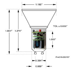
The TPS92310 module (Figure 2) PCB measures 22 (L) x 55 (W) x 19 (H) mm. The module can operate with an AC line input from 90 to 132 VRMS or 180 to 264 VRMS. It can supply 350 mA current into a single string of LEDs, with typically six to seven LEDs in series. The evaluation board is designed to comply with industrial EMC and safety requirements. The user guide, datasheet and application notes will help engineers design a board for their specific application.
Figure 2: The TPS92310 EVM-8W evaluation module, using Texas Instruments' TPS92310 controller IC in a flyback configuration, is designed for A19, PAR30/38, and GU10 applications. (Courtesy of Texas Instruments.)
Another challenge is which of the four topologies – flyback, buck, tapped buck or buck-boost – does a designer select for the LED bulb? Said Smith: "The problem is which one do I pick for my application, and unfortunately the combination of input and output, power factor (PF) and total harmonic distortion (THD) all influence those choices. It's not straightforward."
Power Integrations' RDK-268 reference design kit (Figure 3), as an example, does a good job balancing power factor and THD. The 1.1 W power-factor-corrected LED driver (non-isolated) using the LinkSwitch-PL driver IC, for a non-dimming candelabra lamp replacement design, delivers high power factor (>0.85), low THD (<25%), and low-harmonic content.
Figure 3: The Power Integrations RDK-268 reference design for a 1.1 W power-factor-corrected LED power supply, using the LinkSwitch-PL LNK454DG, is designed to fit into a candelabra lamp base. (Courtesy of Power Integrations.)
"The other thing that is critical for retrofit bulbs in down lighting is the thorny subject of triac dimming, which is a very iterative process to fix because there are many different triacs, and many different dimming circuits," said Smith. "What we tend to do with our reference designs is to specify a list of triac dimmers that this particular circuit will work with."
For instance, the RDK-193 reference design kit from Power Integrations (Figure 4) is a design for a 7 W TRIAC dimmable PAR20 LED driver, using the LinkSwitch-PH LNK403EG. The isolated flyback design delivers high efficiency (greater or equal to 81 percent), and high power factor (>0.90). It is a low cost and low component-count design.
Figure 4: The Power Integrations RDK-193 reference design board for a 7 W PAR20 LED driver, using the LinkSwitch-PH LNK403EG, provides a range of protection features including auto-restart for open control loop and output short circuits, line overvoltage, output overvoltage, and hysteretic thermal shutdown. (Courtesy of Power Integrations)
For MR16 bulb applications, Maxim Integrated offers its MAX16820EVKIT+ evaluation kit for the MAX16840 LED driver with integrated MOSFET, which is compatible with most electronic transformers and cut-angle dimmers. The IC can be used in buck, boost, and buck-boost topologies.
Summary
LED lighting designers have a number of design tradeoffs to consider when selecting a LED driver for their retrofit bulb designs. Designers have to consider a number of specs including topology, temperature, THD, efficiency, power factor, input voltage range, surge ratings, type of heat sink, lifetime, and, of course, cost. All of these design criteria have an impact on the final design.
The good news is that many fundamental decisions are made right on the reference design or evaluation board, allowing the designer to concentrate on areas that are most important. A few examples include meeting a high thermal environment, or ensuring that the design will work over an extended voltage range.
声明:本文内容及配图由入驻作者撰写或者入驻合作网站授权转载。文章观点仅代表作者本人,不代表电子发烧友网立场。文章及其配图仅供工程师学习之用,如有内容侵权或者其他违规问题,请联系本站处理。
举报投诉
发布评论请先 登录
相关推荐
热点推荐
LM3697:高性能三串白光 LED 驱动器的卓越之选
LED 的应用,一款高性能的 LED 驱动器显得尤为重要。今天,我们就来深入了解一下德州仪器(TI)推出的 LM3697 高功效三串白光 LED
MAX16820:2MHz高亮度LED驱动器的卓越之选
MAX16819/MAX16820:2MHz高亮度LED驱动器的卓越之选 在当今的照明设计领域,高亮度LED驱动器的性能和功能对于实现高效、
MAX31840:集成控制MOSFET和深度调光功能的MR16 LED驱动器
的MAX31840,是一款专为可调光12V MR16以及AR111等其他12V照明应用设计的LED驱动器IC,它集成了控制MOSFET和深度调光功能,为照明设计带来了诸多优势。 文件下
MAX20051:2A同步降压LED驱动器的卓越之选
的MAX20050–MAX20053系列2A同步降压LED驱动器,它集成了MOSFET,为照明设计带来了诸多优势。 文件下载: MAX20051.pdf 1. 产品概述 MAX20050–MAX20053是专为
探索PCA9955BTW - ARD评估板:开启LED驱动设计新征程
- ARD评估板,围绕着PCA9955B这款16通道Fm + I²C - bus 57 mA/20V恒流LED驱动器构建,为工程师们提供了一个便捷的测试和设计平台。今天,我们就一起来
PCA9958HN - ARD评估板:24通道SPI总线LED驱动评估利器
便捷的平台,用于测试和设计PCA9958HN这款24通道SPI 4线总线63 mA/5.5 V恒流LED驱动器。下面,我们就来详细了解一下这款评估板。 文件下载: NXP Semico
TLD2252-2EP 后组合灯评估板:开启汽车 LED 照明设计新视角
TLD2252-2EP 后组合灯评估板:开启汽车 LED 照明设计新视角 引言 在汽车电子领域,LED
探索TLD1211SJ评估板:汽车LED照明驱动的理想之选
.pdf 一、评估板概述 TLD1211SJ_EVAL评估板专为汽车LED照明应用而设计,旨在帮
TLD5191HB2W-EVAL评估板:汽车LED驱动的高效解决方案
TLD5191HB2W-EVAL评估板:汽车LED驱动的高效解决方案 在汽车电子领域,LED照明
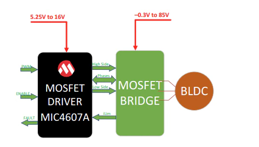
MIC4607A MOSFET驱动器评估板用户指南总结
Microchip Technology MIC4607A MOSFET驱动器评估板用于演示MIC4607A MOSFET驱动器所提供的驱动器
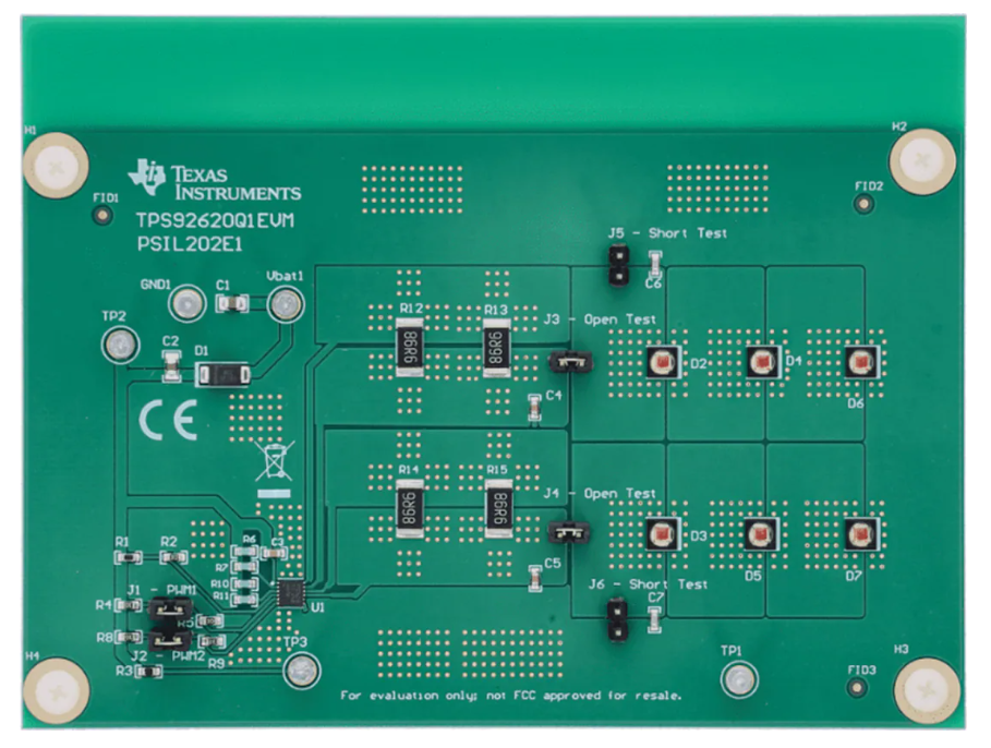
德州仪器TPS92620Q1EVM LED驱动器评估模块技术解析
LED驱动器,具有完整的LED诊断功能,用于汽车照明应用。对于汽车照明终端设备中的线性LED
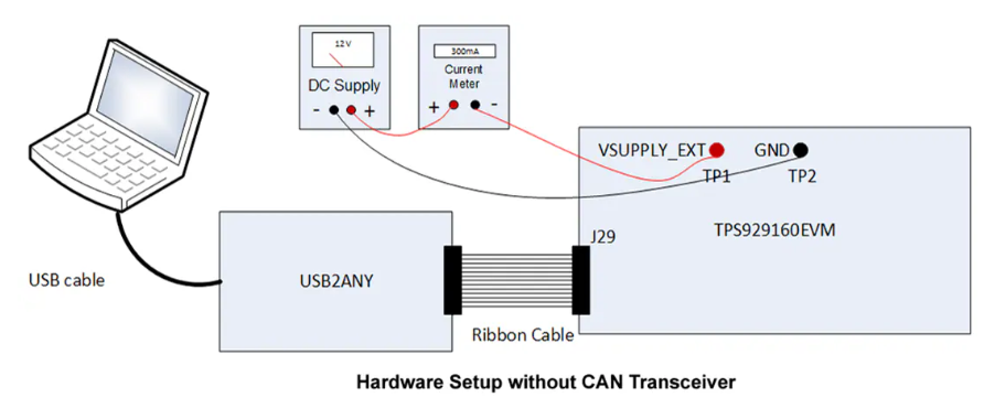
TPS929160-Q1汽车级LED矩阵驱动器评估模块技术解析
通道LED驱动器,带FlexWire接口,旨在满足日益增长的对每个LED灯串单独控制的需求。Texas Instruments TPS929160EVM配有TPS929120CANEVM评估
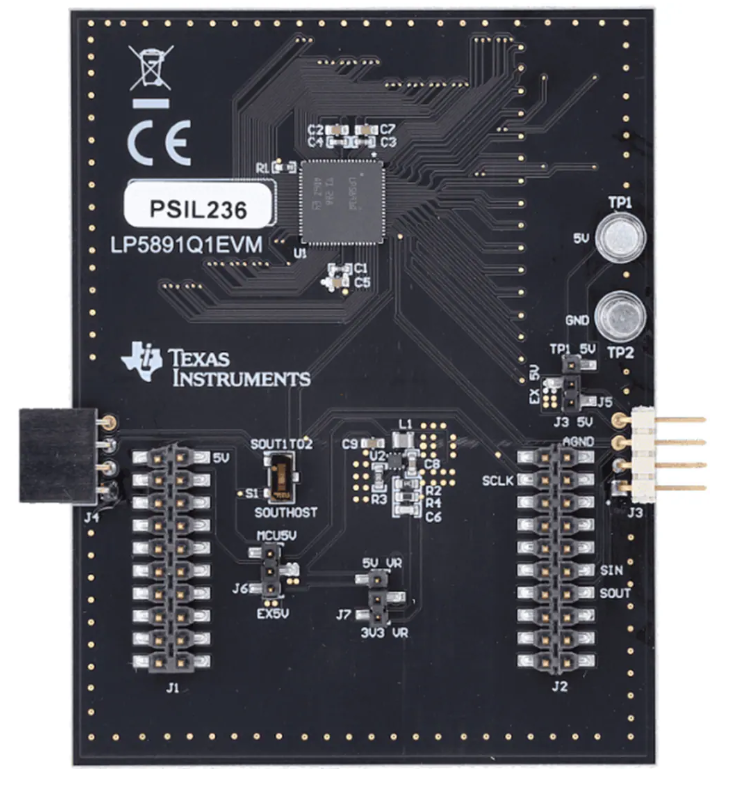
LP5891-Q1 LED矩阵显示驱动器评估模块技术解析
Texas Instruments LP5891Q1EVM驱动器评估模块 (EVM) 用于评估矩阵LED显示驱动器LP5891-Q1的特性、
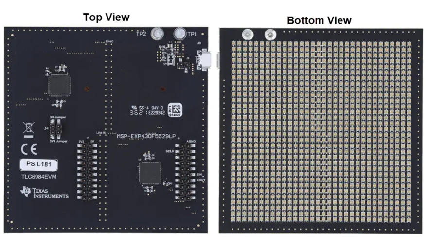
TLC6984EVM LED显示驱动器评估模块技术解析
Texas Instruments TLC6984EVM LED显示驱动器评估模块 (EVM) 用作对TLC6984进行工程演示和评估的参考。TLC984是一款高度集成的共阴极矩阵
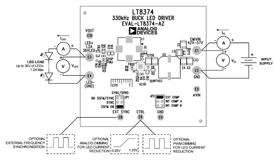
Analog Devices Inc. EVAL-LT8374-AZ LED驱动器评估板数据手册
Analog Devices EVAL-LT8374-AZ LED驱动器评估板用于评估LT8374同步降压


评论