 探索定位红外相机:功能、特性与应用

探索定位红外相机:功能、特性与应用
一、引言
在电子设备日益智能化的今天,定位红外相机作为一种独特的传感器,正发挥着越来越重要的作用。它不仅能追踪多个红外物体,还能作为火焰传感器检测热源位置,在机器人导航、安防监控等领域具有广泛的应用前景。本文将详细介绍一款小型定位红外相机,包括其规格参数、引脚定义、连接方式以及示例代码等内容,希望能为电子工程师们在相关设计中提供参考。
文件下载:SEN0158.pdf
二、相机概述
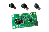
这款定位红外相机具有小巧的外形,能够同时追踪4个红外物体。它的应用场景十分多样,既可以用于带有红外发射器的机器人导航追踪,也能作为光障使用,还能确定物体的运动方向。此外,它还是一个出色的火焰传感器,可用于检测火焰位置,为消防安全等领域提供支持。而且,该相机安装和连接都非常方便,只需要四根线,其中两根用于电源供应,另外两根用于I2C通信。
三、规格参数
1. 电源消耗
该相机支持两种电源规格,分别是3.3V/44mA和5V/48mA,用户可以根据实际需求进行选择。
2. 检测距离
其检测距离范围为0 - 3m,能够满足大多数应用场景的需求。
3. 通信协议
采用I2C通信协议,这种协议具有简单、高效的特点,便于与其他设备进行连接和通信。
4. 检测角度
水平检测角度为33度,垂直检测角度为23度,能够覆盖一定的空间范围。
5. 分辨率
相机的分辨率为128x96像素,并且具备硬件图像处理能力,可同时追踪四个红外发射或反射物体。
6. 尺寸
相机呈圆柱形,尺寸为32 x 16,体积小巧,便于安装和集成。
四、引脚定义
该相机的引脚定义如下:
五、连接示意图
虽然文档中未给出具体的连接示意图,但根据引脚定义和I2C通信的原理,我们可以推测出该相机与其他设备的连接方式。在实际应用中,需要将相机的VCC+和GND分别连接到电源的正负极,SDA和SCL分别连接到主控设备的I2C数据线和时钟线。
六、示例代码
1. 指令说明
当相机检测到信号时,会在第一个位置显示其坐标,其他位置为空(返回1023,1023)。如果相机检测到多个物体,会按照检测顺序排列。若其中一个物体超出视野范围,该位置将为空(返回1023,1023)。该相机同时最多支持4个物体的检测。
2. Arduino代码
以下是使用Arduino控制该相机的示例代码:
// Wii Remote IR sensor test sample code by kako http://www.kako.com
// modified output for Wii - BlobTrack program by RobotFreak http://www.letsmak erobots.com/user/1433
// modified for http://DFRobot.com by Lumi, Jan. 2014
#include < Wire.h >
int IRsensorAddress = 0xB0;
//int IRsensorAddress = 0x58;
int slaveAddress;
int ledPin = 13;
boolean ledState = false;
byte data_buf[16];
int i;
int Ix[4];
int Iy[4];
int s;

void Write_2bytes(byte d1, byte d2)
{
    Wire.beginTransmission(slaveAddress);
    Wire.write(d1);
    Wire.write(d2);
    Wire.endTransmission();
}

void setup()
{
    slaveAddress = IRsensorAddress >> 1; // This results in 0x21 as the address to pass to TWI
    Serial.begin(19200);
    pinMode(ledPin, OUTPUT); // Set the LED pin as output
    Wire.begin();
    // IR sensor initialize
    Write_2bytes(0x30,0x01);
    delay(10);
    Write_2bytes(0x30,0x08);
    delay(10);
    Write_2bytes(0x06,0x90);
    delay(10);
    Write_2bytes(0x08,0xC0);
    delay(10);
    Write_2bytes(0x1A,0x40);
    delay(10);
    Write_2bytes(0x33,0x33);
    delay(10);
    delay(100);
}

void loop()
{
    ledState = !ledState;
    if (ledState) {
        digitalWrite(ledPin,HIGH);
    } else {
        digitalWrite(ledPin,LOW);
    }
    //IR sensor read
    Wire.beginTransmission(slaveAddress);
    Wire.write(0x36);
    Wire.endTransmission();
    Wire.requestFrom(slaveAddress, 16); // Request the 2 byte heading
    for (i = 0; i < 16; i++) {
        data_buf[i] = 0;
    }
    i = 0;
    while(Wire.available() && i < 16) {
        data_buf[i] = Wire.read();
        i++;
    }
    Ix[0] = data_buf[1];
    Iy[0] = data_buf[2];
    s = data_buf[3];
    Ix[0] += (s & 0x30) < < 4;
    Iy[0] += (s & 0xC0) < < 2;
    Ix[1] = data_buf[4];
    Iy[1] = data_buf[5];
    s = data_buf[6];
    Ix[1] += (s & 0x30) < < 4;
    Iy[1] += (s & 0xC0) < < 2;
    Ix[2] = data_buf[7];
    Iy[2] = data_buf[8];
    s = data_buf[9];
    Ix[2] += (s & 0x30) < < 4;
    Iy[2] += (s & 0xC0) < < 2;
    Ix[3] = data_buf[10];
    Iy[3] = data_buf[11];
    s = data_buf[12];
    Ix[3] += (s & 0x30) < < 4;
    Iy[3] += (s & 0xC0) < < 2;
    for(i = 0; i < 4; i++) {
        if (Ix[i] < 1000) {
            Serial.print(" ");
        }
        if (Ix[i] < 100) {
            Serial.print(" ");
        }
        if (Ix[i] < 10) {
            Serial.print(" ");
        }
        Serial.print(int(Ix[i]));
        Serial.print(",");
        if (Iy[i] < 1000) {
            Serial.print(" ");
        }
        if (Iy[i] < 100) {
            Serial.print(" ");
        }
        if (Iy[i] < 10) {
            Serial.print(" ");
        }
        Serial.print(int(Iy[i]));
        if (i < 3) {
            Serial.print(",");
        }
    }
    Serial.println("");
    delay(15);
}
3. Processing代码
以下是使用Processing进行数据可视化的示例代码:
// Example by Tom Igoe
// Modified for http://www.DFRobot.com by Lumi, Jan. 2014
import processing.serial.*;
int lf = 10; // Linefeed in ASCII
String myString = null;
Serial myPort; // The serial port

void setup() {
    // List all the available serial ports
    println(Serial.list());
    // Open the port you are using at the rate you want:
    myPort = new Serial(this, Serial.list()[0], 19200);
    myPort.clear();
    // Throw out the first reading, in case we started reading
    // in the middle of a string from the sender.
    myString = myPort.readStringUntil(lf);
    myString = null;
    size(800,800);
    //frameRate(30);
}

void draw() {
    background(77);
    myString = myPort.readStringUntil(lf);
    if (myString != null) {
        int[] output = int(split(myString, ','));
        println(myString); // display the incoming string
        int xx = output[0];
        int yy = output[1];
        int ww = output[2];
        int zz = output[3];
        int xxx = output[4];
        int yyy = output[5];
        int www = output[6];
        int zzz = output[7];
        ellipseMode(RADIUS); // Set ellipseMode to RADIUS
        fill(255, 0, 0); // Set fill to white
        ellipse(xx, yy, 20, 20);
        ellipseMode(RADIUS); // Set ellipseMode to RADIUS
        fill(0, 255, 0); // Set fill to white
        ellipse(ww, zz, 20, 20);
        ellipseMode(RADIUS); // Set ellipseMode to RADIUS
        fill(0, 0, 255); // Set fill to white
        ellipse(xxx, yyy, 20, 20);
        ellipseMode(RADIUS); // Set ellipseMode to RADIUS
        fill(255); // Set fill to white
        ellipse(www, zzz, 20, 20);
    }
}
七、总结
这款定位红外相机凭借其小巧的外形、多样的功能和便捷的连接方式,为电子工程师们提供了一个强大的工具。通过详细了解其规格参数、引脚定义和示例代码,我们可以更好地将其应用到实际项目中。在实际设计过程中,你是否遇到过类似传感器的应用难题呢?你又是如何解决的呢?欢迎在评论区分享你的经验和见解。
希望本文能帮助电子工程师们更好地理解和使用这款定位红外相机,推动相关领域的技术发展。更多信息可参考[官方文档](https://www.dfrobot.com/wiki/index.php/Positioning_ir_camera 5 - 2 - 17)。
-
I2C通信
+关注
关注
0文章
30浏览量
9451
发布评论请先 登录
探索Vishay TSAL6400红外发射二极管:特性、应用与设计考量
探索 SUNWAVE SW - 30 人体红外感应模块:多功能低成本之选
探索LM9704实时数字图像处理器:功能、特性与应用
探索Microchip数字电源启动套件:功能、特性与应用指南
探索Crimzon® RC Blaster™:数字红外系统的完美之选
短波红外工业相机:材料检测和质量检验的不二之选(以Dalsa相机为例)

微小卫星红外相机双MCU冗余架构的抗辐照可靠性评估
探索 EZ - USB™ FX3 相机套件:快速上手与功能解析
浮思特 | 手机红外热成像相机原理,看不见的“温度世界”
科研级相机是什么?以及影响信噪比的主要因素
紫外工业相机的主要应用


评论