 基于STM32的元器件特性测试仪过程

元器件特性测试仪任务要求
通过编程完成对5种以上元器件特性的测量
能够自动识别元器件
在OLED屏幕上通过图形化的界面显示各种元器件的符号及测量得到的信息
实验环境
硬件:STM32G031G8U6核心板、硬禾学堂制作的底板
软件:STM32CubeMX、CLion、STM32CubeProgrammer
实现思路
首先进行一个大致的元器件类型的判断,再精确地测量元器件的各项属性,最后显示在OLED屏幕上
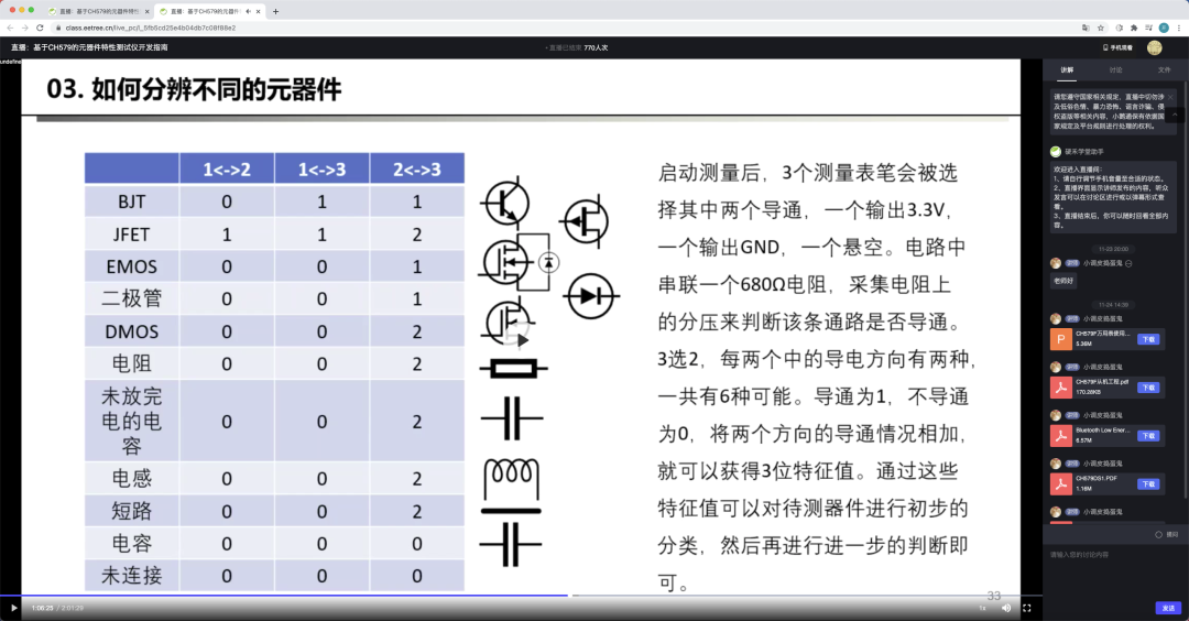
各部分的介绍元器件类型的判断
思路:首先给元器件放电,再轮番给这3pin中的每2pin进行正反地通电,会得到六次结果。将每2pin的结果存储下来,进行排序后根据元器件特性进行判断元器件的类型,初步判断后存下引脚信息并进行参数的测量和屏幕显示,具体参考如图:
代码如下
void QuickCheck() {
QUICKJUDGE result = {0}; //before compare, the result.sat should be sorted
uint8_t BJTFEA[4] = “011”; //BJT
uint8_t DioFea[4] = “001”; //diode/E-MOS
uint8_t ResFea[4] = “002”; //resistance/inductance/charged capacitance
uint8_t CapFea[4] = “000”; //capacitance/no element
uint8_t temp; //交换时用于缓存变量
discharge();
if (QuickTestBetween2Pin(MiddlePort, HighPort, LowPort))
result.Bmh = 1;
/* 共六组测量,代码省略 */
discharge();
if (QuickTestBetween2Pin(LowPort, HighPort, MiddlePort))
result.Blh = 1;
result.Sta[0] = result.Bmh + result.Bhm + ‘0’;
result.Sta[1] = result.Bml + result.Blm + ‘0’;
result.Sta[2] = result.Bhl + result.Blh + ‘0’;
/// Sort the result.sta from little to big
if (result.Sta[0] 》 result.Sta[1])
temp = result.Sta[0], result.Sta[0] = result.Sta[1], result.Sta[1] = temp;
if (result.Sta[1] 》 result.Sta[2])
temp = result.Sta[1], result.Sta[1] = result.Sta[2], result.Sta[2] = temp;
if (result.Sta[0] 》 result.Sta[2])
temp = result.Sta[0], result.Sta[0] = result.Sta[2], result.Sta[2] = temp;
result.Sta[3] = ‘’;
/// 以下是逐个判断元器件特征是否和已知特征符合
if (strcmp(result.Sta, CapFea) == 0) {
if (IsCap_Check()) {
ComponentFound = COMPONENT_CAPACITANCE;
Capacitance_Check(*ComponentParam.CAPPARAM.front, *ComponentParam.CAPPARAM.rear);
Capacitance_Display(ComponentParam);
} else {
Error_Report();
}
} else if (strcmp(result.Sta, DioFea) == 0) {
//TODO:Add emos and diode check
//TODO:Sometimes the caps may be metered as a diode
ComponentFound = COMPONENT_DIODE;
if (result.Bml + result.Blm) {
ComponentParam.DiodeParam.front = &MiddlePort;
ComponentParam.DiodeParam.rear = &LowPort;
} else if (result.Bhm + result.Bmh) {
ComponentParam.DiodeParam.front = &MiddlePort;
ComponentParam.DiodeParam.rear = &HighPort;
} else if (result.Blh + result.Bhl) {
ComponentParam.DiodeParam.front = &LowPort;
ComponentParam.DiodeParam.rear = &HighPort;
}
Diode_Check(*ComponentParam.DiodeParam.front, *ComponentParam.DiodeParam.rear);
Diode_Display(ComponentParam);
} else if (strcmp(result.Sta, ResFea) == 0) {
uint8_t ret = 0;
if (result.Bml + result.Blm) {
ret = IsIndOrRes_Check_Between2Pin(MiddlePort, LowPort, HighPort);
ComponentParam.RESPARAM.front = &MiddlePort;
ComponentParam.RESPARAM.rear = &LowPort;
ComponentParam.INDPARAM.front = &MiddlePort;
ComponentParam.INDPARAM.rear = &LowPort;
} else if (result.Bhm + result.Bmh) {
ret = IsIndOrRes_Check_Between2Pin(HighPort, MiddlePort, LowPort);
ComponentParam.RESPARAM.front = &MiddlePort;
ComponentParam.RESPARAM.rear = &HighPort;
ComponentParam.INDPARAM.front = &MiddlePort;
ComponentParam.INDPARAM.rear = &HighPort;
} else if (result.Blh + result.Bhl) {
ret = IsIndOrRes_Check_Between2Pin(LowPort, HighPort, MiddlePort);
ComponentParam.RESPARAM.front = &LowPort;
ComponentParam.RESPARAM.rear = &HighPort;
ComponentParam.INDPARAM.front = &LowPort;
ComponentParam.INDPARAM.rear = &HighPort;
}
if (ret == 1) {
Inductance_Check(*ComponentParam.INDPARAM.front, *ComponentParam.INDPARAM.rear);
Inductance_Display(ComponentParam);
} else if (ret == 2) {
Resistance_Check(*ComponentParam.RESPARAM.front, *ComponentParam.RESPARAM.rear);
Resistance_Display(ComponentParam);
} else {
Error_Report();
}
} else if (strcmp(result.Sta, BJTFEA) == 0) {
ComponentFound = COMPONENT_BJT;
if (result.Bhm + result.Bmh) {
ComponentParam.BJTPARAM.b = &LowPort;
ComponentParam.BJTPARAM.Channel = result.Blm;
} else if (result.Blm + result.Bml) {
ComponentParam.BJTPARAM.b = &HighPort;
ComponentParam.BJTPARAM.Channel = result.Bhl;
} else {
ComponentParam.BJTPARAM.b = &MiddlePort;
ComponentParam.BJTPARAM.Channel = result.Bmh;
}
BJT_Check();
BJT_Display(ComponentParam);
} else {
Error_Report();
}
discharge();
}
区分电阻和电感
可以给元器件充电后断电,如果检测到下端不为低电平,那就是电感。具体代码如下
/**
* @brief check the element is a inductance or a resistance
* @note firstly,set the fromPin to High and set the toPin to low
* the current direction will like that and the ADC will set here:
* fromPin---element---680r---toPin
* VCC ADC1 GND
* secondly,set the fromPin to Low and set a 470k to protect the io
* the current direction will like that and the ADC will set here:
* fromPin---470k---element---680r---toPin
* GND ADC2 GND
* if it is a inductance the ADC1 and the ADC2 will get a voltage
* while if it is a resistance the ADC1 will get a voltage and the ADC2 will be GND
* @param fromPort
* @param toPort
* @param unusedPort
* @return return 0 if it is no element ,
* return 1 if it is a inductance and
* return 2 if it is a resistance
*/
uint8_t IsIndOrRes_Check_Between2Pin(MEASUREPORT fromPort, MEASUREPORT toPort, MEASUREPORT unusedPort) {
uint16_t adcVol1, adcVol2;
MeasurePort_Init(fromPort, PORT_WITH_NONE, GPIO_PIN_SET);
MeasurePort_Init(toPort, PORT_WITH_680, GPIO_PIN_RESET);
MeasurePort_Init(unusedPort, PORT_FLOATING, GPIO_PIN_RESET);
HAL_GPIO_ReInit(toPort.PIN_WITH_NONE.GPIOx, toPort.PIN_WITH_NONE.GPIO_Pin, GPIO_MODE_ANALOG);
adcVol1 = GetVol(toPort);
MeasurePort_Init(fromPort, PORT_WITH_470K, GPIO_PIN_RESET);
adcVol2 = GetVol(toPort);
if ((adcVol1 《 ADCZERO) && (adcVol2 《 ADCZERO)) {
return 0;
} else if (adcVol2 《 ADCZERO) {
ComponentParam.INDPARAM.front = &fromPort;
ComponentParam.INDPARAM.rear = &toPort;
return 2;
} else {
ComponentParam.RESPARAM.front = &fromPort;
ComponentParam.RESPARAM.rear = &toPort;
return 1;
}
}
电阻的测量
电阻的参数主要有电阻值,可通过分压法测量。
首先使用680r电阻,电阻接在上端和下端各测试一次,并计算电阻值。如果电阻阻值过大,可以换用470k电阻。代码如下
/**
* @brief measure the value of resistance
* @note first measure will set as follows:
* FrontPort---resistance---680r---RearPort
* GND ADC VCC
* second measure will set as follows:
* FrontPort---680r---resistance---RearPormt
* GND ADC VCC
* third and forth measure will use the 470k resistance
* to instead the 680r to have a more accurate value
* when the resistance is big.
* @param FrontPort
* @param RearPort
*/
//TODO:the resistance of the ADC may cause some deviations when use the 470k resistance
void Resistance_Check(MEASUREPORT FrontPort, MEASUREPORT RearPort) {
uint16_t adcget[4];
float res[4];
MEASUREPORT unusedPort = GetUnusedPort(&FrontPort, &RearPort);
/// MeasurePort_Init函数用于重新初始化一个pin上的3个引脚至指定电阻和电平。
/// 如使用680r电阻,重新初始化其他两个引脚为浮空高阻,将连接着680r电阻的引脚设为指定电平
MeasurePort_Init(FrontPort, PORT_WITH_NONE, GPIO_PIN_RESET);
MeasurePort_Init(RearPort, PORT_WITH_680, GPIO_PIN_SET);
MeasurePort_Init(unusedPort, PORT_FLOATING, GPIO_PIN_RESET);
/// 重新初始化ADC引脚。ADC引脚一般为提供电阻的那组引脚中未接电阻的引脚
HAL_GPIO_ReInit(RearPort.PIN_WITH_NONE.GPIOx, RearPort.PIN_WITH_NONE.GPIO_Pin, GPIO_MODE_ANALOG);
/// GetVol函数用于测量指定引脚组中未接电阻那个引脚的电压
adcget[0] = GetVol(RearPort);
res[0] = 680 / (3300.0 / adcget[0] - 1);
MeasurePort_Init(FrontPort, PORT_WITH_680, GPIO_PIN_RESET);
MeasurePort_Init(RearPort, PORT_WITH_NONE, GPIO_PIN_SET);
MeasurePort_Init(unusedPort, PORT_FLOATING, GPIO_PIN_RESET);
HAL_GPIO_ReInit(FrontPort.PIN_WITH_NONE.GPIOx, FrontPort.PIN_WITH_NONE.GPIO_Pin, GPIO_MODE_ANALOG);
adcget[1] = GetVol(FrontPort);
res[1] = 680 / (adcget[1] / 3300.0) - 680;
if ((res[0] + res[1]) 》 1000) {
/* 与上面的代码类似,仅将680R改为470K电阻,省略 */
}
if ((res[0] + res[1]) 《= 10000) {
ComponentParam.RESPARAM.ResVal = (uint32_t) (res[0] + res[1]) / 2;
} else if ((res[0] + res[1]) 《= 1000000) {
qsort(res, 4, sizeof(float), cmpfunc);
ComponentParam.RESPARAM.ResVal = (uint32_t) (res[1] + res[2]) / 2;
} else {
ComponentParam.RESPARAM.ResVal = (uint32_t) (res[2] + res[3]) / 2;
}
}
电感的测量
电感的测量可以通过充电后测量放电时间来大致计算出电感值
/**
* @brief charge the inductance and discharge it
* @note get the discharge time and then calculate the value of the inductance
* the current direction will like that and the ADC will set here:
* FrontPort---680r---inductance---RearPort
* VCC ADC GND
* after charge, set the FrontPort to low
* the current direction will like that and the ADC will set here:
* FrontPort---680r---inductance---RearPort
* GND ADC GND
* if the discharge speed is too fast, use the 470k to instead and test again.
* @note calculating the value of the inductance is not verified
* @param FrontPort
* @param RearPort
*/
void Inductance_Check(MEASUREPORT FrontPort, MEASUREPORT RearPort) {
uint16_t adcget1, adcget2;
uint16_t time1, time2;
uint16_t i = 0;
MEASUREPORT unusedPort = GetUnusedPort(&FrontPort, &RearPort);
MeasurePort_Init(FrontPort, PORT_WITH_680, GPIO_PIN_SET);
MeasurePort_Init(RearPort, PORT_WITH_NONE, GPIO_PIN_RESET);
MeasurePort_Init(unusedPort, PORT_FLOATING, GPIO_PIN_RESET);
HAL_GPIO_ReInit(FrontPort.PIN_WITH_NONE.GPIOx, FrontPort.PIN_WITH_NONE.GPIO_Pin, GPIO_MODE_ANALOG);
HAL_Delay(100);
adcget1 = GetVol(FrontPort);
MeasurePort_Init(FrontPort, PORT_WITH_680, GPIO_PIN_RESET);
HAL_GPIO_ReInit(FrontPort.PIN_WITH_NONE.GPIOx, FrontPort.PIN_WITH_NONE.GPIO_Pin, GPIO_MODE_ANALOG);
time1 = HAL_GetTick();
while (i 《 0xffff) {
adcget2 = GetVol(FrontPort);
i++;
if (adcget2 《 ADCZERO) {
break;
}
}
time2 = HAL_GetTick();
if (i 《 100) {
MeasurePort_Init(FrontPort, PORT_WITH_680, GPIO_PIN_SET);
MeasurePort_Init(RearPort, PORT_WITH_NONE, GPIO_PIN_RESET);
MeasurePort_Init(unusedPort, PORT_FLOATING, GPIO_PIN_RESET);
HAL_GPIO_ReInit(FrontPort.PIN_WITH_NONE.GPIOx, FrontPort.PIN_WITH_NONE.GPIO_Pin, GPIO_MODE_ANALOG);
HAL_Delay(100);
adcget1 = GetVol(FrontPort);
MeasurePort_Init(FrontPort, PORT_WITH_470K, GPIO_PIN_RESET);
HAL_GPIO_ReInit(FrontPort.PIN_WITH_NONE.GPIOx, FrontPort.PIN_WITH_NONE.GPIO_Pin, GPIO_MODE_ANALOG);
time1 = HAL_GetTick();
while (i 《 0xffff) {
adcget2 = GetVol(FrontPort);
i++;
if (adcget2 《 ADCZERO) {
break;
}
}
time2 = HAL_GetTick();
ComponentParam.INDPARAM.IndVal = (time2 - time1) / (470000 * log(adcget1 / (float) adcget2)) / 1000;
} else {
ComponentParam.INDPARAM.IndVal = (time2 - time1) / (680 * log(adcget1 / (float) adcget2)) / 1000;
}
}
电容的测量
和电感类似,充电后放电,计算放电的时间。
需要注意的是这边似乎可能会对有极性的电容进行了反向充电,或者对低耐压的电容充过压,暂时没想到好的解决方法。
/**
* @brief get the value of the capacitance
* @note charge the cap and use a 680r res to discharge the cap
* calculate the value of the cap by the discharge time
* if the discharge speed is too fast, use 470k to instead the 680r
* @warning when checking the electrolytic and tantalum capacitance
* it is important to avoid reverse connection
* @param FrontPort
* @param RearPort
*/
//TODO:the value may not accurate, may caused by HAL_GetTick.
//TODO:Using a timer to caculate the discharge time may better.
void Capacitance_Check(MEASUREPORT FrontPort, MEASUREPORT RearPort) {
uint16_t adcget1, adcget2;
uint16_t time1, time2;
uint16_t i = 0;
MEASUREPORT unusedPort = GetUnusedPort(&FrontPort, &RearPort);
MeasurePort_Init(FrontPort, PORT_WITH_680, GPIO_PIN_SET);
MeasurePort_Init(RearPort, PORT_WITH_NONE, GPIO_PIN_RESET);
MeasurePort_Init(unusedPort, PORT_FLOATING, GPIO_PIN_RESET);
HAL_Delay(100);
adcget1 = GetVol(FrontPort);
MeasurePort_Init(FrontPort, PORT_WITH_680, GPIO_PIN_SET);
HAL_GPIO_ReInit(FrontPort.PIN_WITH_NONE.GPIOx, FrontPort.PIN_WITH_NONE.GPIO_Pin, GPIO_MODE_ANALOG);
time1 = HAL_GetTick();
while (i 《 0xffff) {
adcget2 = GetVol(FrontPort);
i++;
if (adcget2 《 ADCZERO) {
time2 = HAL_GetTick();
break;
}
}
if (i 《 100) {
MeasurePort_Init(FrontPort, PORT_WITH_680, GPIO_PIN_SET);
HAL_Delay(100);
adcget1 = GetVol(FrontPort);
MeasurePort_Init(FrontPort, PORT_WITH_470K, GPIO_PIN_SET);
HAL_GPIO_ReInit(FrontPort.PIN_WITH_NONE.GPIOx, FrontPort.PIN_WITH_NONE.GPIO_Pin, GPIO_MODE_ANALOG);
time1 = HAL_GetTick();
while (i 《 0xffff) {
adcget2 = GetVol(FrontPort);
i++;
if (adcget2 《 ADCZERO) {
time2 = HAL_GetTick();
break;
}
}
ComponentParam.CAPPARAM.CapVal = (time2 - time1) / (470000 * log(adcget1 / (float) adcget2)) / 1000;
} else {
ComponentParam.CAPPARAM.CapVal = (time2 - time1) / (680 * log(adcget1 / (float) adcget2)) / 1000;
}
}
二极管的测量
二极管的测量最为简单,直接测正反压降取小的即可
/**
* @brief get the voltage drop of the diode
* @note the current direction will like that and the ADC will set here:
* frontPort---680r---diode---680---rearPort
* VCC ADC1 ADC2 GND
* if the voltage of the diode is close to 3.3V
* exchange the VCC and GND and test it again
* @param FrontPort
* @param RearPort
*/
void Diode_Check(MEASUREPORT FrontPort, MEASUREPORT RearPort) {
uint16_t adcget1, adcget2;
uint16_t dropVol;
MEASUREPORT unusedPort = GetUnusedPort(&FrontPort, &RearPort);
MeasurePort_Init(FrontPort, PORT_WITH_680, GPIO_PIN_SET);
MeasurePort_Init(RearPort, PORT_WITH_680, GPIO_PIN_RESET);
MeasurePort_Init(unusedPort, PORT_FLOATING, GPIO_PIN_RESET);
HAL_GPIO_ReInit(FrontPort.PIN_WITH_NONE.GPIOx, FrontPort.PIN_WITH_NONE.GPIO_Pin, GPIO_MODE_ANALOG);
HAL_GPIO_ReInit(RearPort.PIN_WITH_NONE.GPIOx, RearPort.PIN_WITH_NONE.GPIO_Pin, GPIO_MODE_ANALOG);
adcget1 = GetVol(FrontPort);
adcget2 = GetVol(RearPort);
dropVol = abs(adcget1 - adcget2);
if (dropVol 》 3000) {
MeasurePort_Init(FrontPort, PORT_WITH_680, GPIO_PIN_RESET);
MeasurePort_Init(RearPort, PORT_WITH_680, GPIO_PIN_SET);
MeasurePort_Init(unusedPort, PORT_FLOATING, GPIO_PIN_RESET);
HAL_GPIO_ReInit(FrontPort.PIN_WITH_NONE.GPIOx, FrontPort.PIN_WITH_NONE.GPIO_Pin, GPIO_MODE_ANALOG);
HAL_GPIO_ReInit(RearPort.PIN_WITH_NONE.GPIOx, RearPort.PIN_WITH_NONE.GPIO_Pin, GPIO_MODE_ANALOG);
adcget1 = GetVol(FrontPort);
adcget2 = GetVol(RearPort);
dropVol = abs(adcget1 - adcget2);
MEASUREPORT *temp = ComponentParam.DiodeParam.rear;
ComponentParam.DiodeParam.rear = ComponentParam.DiodeParam.front;
ComponentParam.DiodeParam.front = temp;
}
ComponentParam.DiodeParam.Uon = dropVol;
}
三极管的测量
可以知道得到0次导通的那两个脚为集电极和发射极,因为基极与其他两个集都能导通一次。再检查基极向集电极或者发射集是否导通,导通即为NPN,不导通即为PNP。分出三极管类型后测量放大和倒置状态下的hFE,也就是beta,大者即为放大状态和正确的放大倍数。
三极管测量hFE的方法:以NPN为例,给基极和集电极通过一个680R电阻接高电平,测量基极和集电极电压。如果基极电压不为接近0,表明三极管处于放大状态,基极电流为(3300mv-adcget1)/680r,集电极电流为(3300mv-adcget2)/680r,hFE即为(3300 - adcget2) / (3300 - adcget1)。如果基极电压接近0,表明三极管基极电流过大,处于饱和状态。增大基极电阻再试一次。
/* 晶体管极性 */
#define P_CHANNEL 1 //NPN
#define N_CHANNEL 0 //PNP
/**
* @brief check the bjt
* @note copy from the program of the CH579
* @attention haven‘t tested yet
*/
void BJT_Check() {
uint16_t adcget1, adcget2, adcget3, adcget4;
uint16_t hfe1, hfe2;
if (ComponentParam.BJTPARAM.Channel == P_CHANNEL) {
if (ComponentParam.BJTPARAM.b == &LowPort) {
discharge();
hfe1 = BJT_Check_NPN(LowPort, MiddlePort, HighPort);
discharge();
hfe2 = BJT_Check_NPN(LowPort, HighPort, MiddlePort);
if (hfe1 》 hfe2) {
ComponentParam.BJTPARAM.c = &MiddlePort;
ComponentParam.BJTPARAM.e = &HighPort;
ComponentParam.BJTPARAM.hFE = hfe1;
} else {
ComponentParam.BJTPARAM.c = &HighPort;
ComponentParam.BJTPARAM.e = &MiddlePort;
ComponentParam.BJTPARAM.hFE = hfe2;
}
} else if (ComponentParam.BJTPARAM.b == &HighPort) {
discharge();
hfe1 = BJT_Check_NPN(HighPort, LowPort, MiddlePort);
discharge();
hfe2 = BJT_Check_NPN(HighPort, MiddlePort, LowPort);
if (hfe1 》 hfe2) {
ComponentParam.BJTPARAM.c = &LowPort;
ComponentParam.BJTPARAM.e = &MiddlePort;
ComponentParam.BJTPARAM.hFE = hfe1;
} else {
ComponentParam.BJTPARAM.c = &MiddlePort;
ComponentParam.BJTPARAM.e = &LowPort;
ComponentParam.BJTPARAM.hFE = hfe2;
}
} else {
discharge();
hfe1 = BJT_Check_NPN(MiddlePort, HighPort, LowPort);
discharge();
hfe2 = BJT_Check_NPN(MiddlePort, LowPort, HighPort);
if (hfe1 》 hfe2) {
ComponentParam.BJTPARAM.c = &HighPort;
ComponentParam.BJTPARAM.e = &LowPort;
ComponentParam.BJTPARAM.hFE = hfe1;
} else {
ComponentParam.BJTPARAM.c = &LowPort;
ComponentParam.BJTPARAM.e = &HighPort;
ComponentParam.BJTPARAM.hFE = hfe2;
}
}
} else {
if (ComponentParam.BJTPARAM.b == &LowPort) {
discharge();
hfe1 = BJT_Check_PNP(LowPort, MiddlePort, HighPort);
discharge();
hfe2 = BJT_Check_PNP(LowPort, HighPort, MiddlePort);
if (hfe1 》 hfe2) {
ComponentParam.BJTPARAM.c = &MiddlePort;
ComponentParam.BJTPARAM.e = &HighPort;
ComponentParam.BJTPARAM.hFE = hfe1;
} else {
ComponentParam.BJTPARAM.c = &HighPort;
ComponentParam.BJTPARAM.e = &MiddlePort;
ComponentParam.BJTPARAM.hFE = hfe2;
}
} else if (ComponentParam.BJTPARAM.b == &HighPort) {
discharge();
hfe1 = BJT_Check_PNP(HighPort, LowPort, MiddlePort);
discharge();
hfe2 = BJT_Check_PNP(HighPort, MiddlePort, LowPort);
if (hfe1 》 hfe2) {
ComponentParam.BJTPARAM.c = &LowPort;
ComponentParam.BJTPARAM.e = &MiddlePort;
ComponentParam.BJTPARAM.hFE = hfe1;
} else {
ComponentParam.BJTPARAM.c = &MiddlePort;
ComponentParam.BJTPARAM.e = &LowPort;
ComponentParam.BJTPARAM.hFE = hfe2;
}
} else {
discharge();
hfe1 = BJT_Check_PNP(MiddlePort, HighPort, LowPort);
discharge();
hfe2 = BJT_Check_PNP(MiddlePort, LowPort, HighPort);
if (hfe1 》 hfe2) {
ComponentParam.BJTPARAM.c = &HighPort;
ComponentParam.BJTPARAM.e = &LowPort;
ComponentParam.BJTPARAM.hFE = hfe1;
} else {
ComponentParam.BJTPARAM.c = &LowPort;
ComponentParam.BJTPARAM.e = &HighPort;
ComponentParam.BJTPARAM.hFE = hfe2;
}
}
}
}
/**
* @brief test the hfe with the imaginary collector and emitter
* @param bPort the base port
* @param cPort the imaginary collector
* @param ePort the imaginary emitter
* @return hfe
*/
uint16_t BJT_Check_PNP(MEASUREPORT bPort, MEASUREPORT cPort, MEASUREPORT ePort) {
uint16_t adcget1, adcget2;
uint16_t hfe;
MeasurePort_Init(ePort, PORT_WITH_680, GPIO_PIN_SET);
MeasurePort_Init(bPort, PORT_WITH_680, GPIO_PIN_RESET);
MeasurePort_Init(cPort, PORT_WITH_NONE, GPIO_PIN_RESET);
HAL_GPIO_ReInit(bPort.PIN_WITH_NONE.GPIOx, bPort.PIN_WITH_NONE.GPIO_Pin, GPIO_MODE_ANALOG);
adcget1 = GetVol(bPort);
if (adcget1 》 ADCZERO) {
HAL_GPIO_ReInit(ePort.PIN_WITH_NONE.GPIOx, ePort.PIN_WITH_NONE.GPIO_Pin, GPIO_MODE_ANALOG);
adcget2 = GetVol(ePort);
hfe = (3300 - adcget2) / adcget1;
} else {
MeasurePort_Init(bPort, PORT_WITH_470K, GPIO_PIN_RESET);
HAL_GPIO_ReInit(bPort.PIN_WITH_NONE.GPIOx, bPort.PIN_WITH_NONE.GPIO_Pin, GPIO_MODE_ANALOG);
adcget1 = GetVol(bPort);
HAL_GPIO_ReInit(ePort.PIN_WITH_NONE.GPIOx, ePort.PIN_WITH_NONE.GPIO_Pin, GPIO_MODE_ANALOG);
adcget2 = GetVol(ePort);
hfe = (470000 * (3300 - adcget2) / 1000) / (680 * adcget1 / 1000) - 1;
}
return hfe;
}
/**
* @brief test the hfe with the imaginary collector and emitter
* @param bPort the base port
* @param cPort the imaginary collector
* @param ePort the imaginary emitter
* @return hfe
*/
uint16_t BJT_Check_NPN(MEASUREPORT bPort, MEASUREPORT cPort, MEASUREPORT ePort) {
uint16_t adcget1, adcget2;
uint16_t hfe;
MeasurePort_Init(ePort, PORT_WITH_NONE, GPIO_PIN_RESET);
MeasurePort_Init(cPort, PORT_WITH_680, GPIO_PIN_SET);
MeasurePort_Init(bPort, PORT_WITH_680, GPIO_PIN_SET);
HAL_GPIO_ReInit(bPort.PIN_WITH_NONE.GPIOx, bPort.PIN_WITH_NONE.GPIO_Pin, GPIO_MODE_ANALOG);
adcget1 = GetVol(bPort);
if (adcget1 》 ADCZERO) {
HAL_GPIO_ReInit(cPort.PIN_WITH_NONE.GPIOx, cPort.PIN_WITH_NONE.GPIO_Pin, GPIO_MODE_ANALOG);
adcget2 = GetVol(cPort);
hfe = (3300 - adcget2) / (3300 - adcget1);
} else {
MeasurePort_Init(bPort, PORT_WITH_470K, GPIO_PIN_RESET);
HAL_GPIO_ReInit(bPort.PIN_WITH_NONE.GPIOx, bPort.PIN_WITH_NONE.GPIO_Pin, GPIO_MODE_ANALOG);
adcget1 = GetVol(bPort);
HAL_GPIO_ReInit(cPort.PIN_WITH_NONE.GPIOx, cPort.PIN_WITH_NONE.GPIO_Pin, GPIO_MODE_ANALOG);
adcget2 = GetVol(cPort);
hfe = (470000 * (3300 - adcget2) / 1000) / (680 * (3300 - adcget1) / 1000);
}
return hfe;
}
OLED的显示
元器件的各种信息通过一个全局共用体传递。OLED使用软件I2C进行驱动,具体的库和实现省略,我直播时也有讲过,可以参考我整理的一些驱动。
由于macOS上缺少一些取模软件,这里我暂时使用字符象形一下元件,比如电阻:
void Resistance_Display(COMPONENTPARAMETER ComParam) {
char ch[70];
sprintf(ch, “Res %d-[]-%dR=%d Ohm”,
ConvPinToNum(ComParam.RESPARAM.front-》PIN_WITH_NONE.GPIO_Pin),
ConvPinToNum(ComParam.RESPARAM.rear-》PIN_WITH_NONE.GPIO_Pin),
ComParam.RESPARAM.ResVal);
OLED_Clear();
OLED_ShowString(0, 0, (uint8_t *) ch, 12);
}
一些中间层的函数
QuickTestBetween2Pin
测试两脚之间有没有元件
/**
* @brief test if it is a element between 2 pins
* @note the current direction will like that and the ADC will set here:
* fromPort---element---680r---toPort
* VCC ADC GND
* the toPort will have a 680r resistance to serial connect into the current direction
* and have a no-resistance Pin which will be used as a ADC to
* get the voltage and calculate the equivalent resistance of the element
* @param fromPort the current from, will be set high
* @param toPort the current to, will be set low and use a 680r resistance
* @retval if it is a element between fromPort and toPort
*/
uint8_t QuickTestBetween2Pin(MEASUREPORT fromPort, MEASUREPORT toPort, MEASUREPORT unusedPort) {
MeasurePort_Init(fromPort, PORT_WITH_NONE, GPIO_PIN_SET);
MeasurePort_Init(toPort, PORT_WITH_680, GPIO_PIN_RESET);
MeasurePort_Init(unusedPort, PORT_FLOATING, GPIO_PIN_SET);
HAL_GPIO_ReInit(toPort.PIN_WITH_NONE.GPIOx, toPort.PIN_WITH_NONE.GPIO_Pin, GPIO_MODE_ANALOG);
HAL_Delay(50);
uint16_t ADCVol = GetVol(toPort);
return ADCVol 》 ADCZERO;
}
GetVol
测量指定脚位电压
/**
* @brief get the voltage of the no-resistance pin in the
* selected pin group.
* @param PinGroup
* @return the average voltage in 5 times test (mv)
*/
uint16_t GetVol(MEASUREPORT PinGroup) {
/**
* arrget[0]-》PA5
* arrget[1]-》PA6
* arrget[2]-》PA7
* arrget[3]-》V_ref
*/
uint16_t arrget[4] = {0};
uint16_t vol = 0, vdda = 0;
uint16_t vref = *(__IO uint16_t *) 0x1FFF75AA;
for (uint8_t i = 0; i 《 5; i++) {
for (uint8_t j = 0; j 《 4; j++) {
arrget[j] += HAL_ADC_Read(&hadc1);
}
}
arrget[3] /= 5;
HAL_ADC_Stop(&hadc1);
vdda = (uint16_t) (vref * 3000.0 / arrget[3]);
switch (PinGroup.PIN_WITH_NONE.GPIO_Pin) {
case GPIO_PIN_5:
vol = arrget[0] * 3300 / 4096.0 / 5;
break;
case GPIO_PIN_6:
vol = arrget[1] * 3300 / 4096.0 / 5;
break;
case GPIO_PIN_7:
vol = arrget[2] * 3300 / 4096.0 / 5;
break;
default:
break;
}
return vol;
}
discharge
给元器件放电
/**
* @brief discharge the element
* @param None
* @retval None
*/
void discharge() {
MeasurePort_Init(HighPort, PORT_WITH_NONE, GPIO_PIN_RESET);
MeasurePort_Init(MiddlePort, PORT_WITH_NONE, GPIO_PIN_RESET);
MeasurePort_Init(LowPort, PORT_WITH_NONE, GPIO_PIN_RESET);
HAL_Delay(50);
}
MeasurePort_Init
重新初始化一个pin上的3个引脚至指定电阻和电平
/**
* @brief Init the selected test group
* @param port the selected test group
* @param mode select the resistance and its pin
* @param PinState test pin power state select
* @retval None
*/
void MeasurePort_Init(MEASUREPORT port, PORTMODE mode, GPIO_PinState PinState) {
switch (mode) {
case PORT_WITH_NONE:
HAL_GPIO_ReInit(port.PIN_WITH_NONE.GPIOx, port.PIN_WITH_NONE.GPIO_Pin, GPIO_MODE_OUTPUT_PP);
HAL_GPIO_ReInit(port.PIN_WITH_680.GPIOx, port.PIN_WITH_680.GPIO_Pin, GPIO_MODE_INPUT);
HAL_GPIO_ReInit(port.PIN_WITH_470K.GPIOx, port.PIN_WITH_470K.GPIO_Pin, GPIO_MODE_INPUT);
HAL_GPIO_WritePin(port.PIN_WITH_NONE.GPIOx, port.PIN_WITH_NONE.GPIO_Pin, PinState);
break;
case PORT_WITH_680:
HAL_GPIO_ReInit(port.PIN_WITH_NONE.GPIOx, port.PIN_WITH_NONE.GPIO_Pin, GPIO_MODE_INPUT);
HAL_GPIO_ReInit(port.PIN_WITH_680.GPIOx, port.PIN_WITH_680.GPIO_Pin, GPIO_MODE_OUTPUT_PP);
HAL_GPIO_ReInit(port.PIN_WITH_470K.GPIOx, port.PIN_WITH_470K.GPIO_Pin, GPIO_MODE_INPUT);
HAL_GPIO_WritePin(port.PIN_WITH_680.GPIOx, port.PIN_WITH_680.GPIO_Pin, PinState);
break;
case PORT_WITH_470K:
HAL_GPIO_ReInit(port.PIN_WITH_NONE.GPIOx, port.PIN_WITH_NONE.GPIO_Pin, GPIO_MODE_INPUT);
HAL_GPIO_ReInit(port.PIN_WITH_680.GPIOx, port.PIN_WITH_680.GPIO_Pin, GPIO_MODE_INPUT);
HAL_GPIO_ReInit(port.PIN_WITH_470K.GPIOx, port.PIN_WITH_470K.GPIO_Pin, GPIO_MODE_OUTPUT_PP);
HAL_GPIO_WritePin(port.PIN_WITH_470K.GPIOx, port.PIN_WITH_470K.GPIO_Pin, PinState);
break;
case PORT_FLOATING:
HAL_GPIO_ReInit(port.PIN_WITH_NONE.GPIOx, port.PIN_WITH_NONE.GPIO_Pin, GPIO_MODE_INPUT);
HAL_GPIO_ReInit(port.PIN_WITH_680.GPIOx, port.PIN_WITH_680.GPIO_Pin, GPIO_MODE_INPUT);
HAL_GPIO_ReInit(port.PIN_WITH_470K.GPIOx, port.PIN_WITH_470K.GPIO_Pin, GPIO_MODE_INPUT);
default:
break;
}
HAL_ADC_Read
进行一次ADC的测量
uint16_t HAL_ADC_Read() {
HAL_ADC_Start(&hadc1);
HAL_ADC_PollForConversion(&hadc1,0xff);
return HAL_ADC_GetValue(&hadc1);
}
HAL_GPIO_ReInit
重新初始化GPIO
void HAL_GPIO_ReInit(GPIO_TypeDef *GPIOx, uint16_t GPIO_Pin, uint32_t Mode){
HAL_GPIO_DeInit(GPIOx,GPIO_Pin);
GPIO_InitTypeDef GPIO_InitStruct = {0};
GPIO_InitStruct.Pin = GPIO_Pin;
GPIO_InitStruct.Mode = Mode;
GPIO_InitStruct.Pull = GPIO_NOPULL;
HAL_GPIO_Init(GPIOx, &GPIO_InitStruct);
}
ConvPinToNum
将GPIO_PIN_X转换成引脚1/2/3
uint16_t ConvPinToNum(uint16_t GPIO_Pin) {
if (GPIO_Pin == GPIO_PIN_5) {
return 1;
} else if (GPIO_Pin == GPIO_PIN_6) {
return 2;
} else if (GPIO_Pin == GPIO_PIN_7) {
return 3;
}
return 0;
}
遇到的问题
STM32的ADC采得电压不是很准确,使用校准后漂移更为离谱
电阻测量时使用470k电阻时测得电阻偏差较大,猜测可能为ADC内阻导致
电容的测量暂未想到较好的方案
FLASH占用较高(约90%),以后可以使用LL库代替HAL库来节省FLASH开支
由于忙于第四期FPGA活动等事,仅针对部分元件为了直播从沁恒于浩然老师的代码中移植整理了部分代码,同时电感的代码仅移植也未经测试
原文标题:基于STM32的元器件特性测试
文章出处:【微信公众号:FPGA入门到精通】欢迎添加关注!文章转载请注明出处。
责任编辑:haq
-
电子元器件
+关注
关注
134文章
3960浏览量
114422 -
STM32
+关注
关注
2313文章
11191浏览量
374580
原文标题:基于STM32的元器件特性测试
文章出处:【微信号:xiaojiaoyafpga,微信公众号:电子森林】欢迎添加关注!文章转载请注明出处。
发布评论请先 登录
励磁系统开环小电流测试仪:技术原理与现场应用
电池测试仪:电池性能大考验,这款测试仪来“打怪”
LCR测试仪与阻抗分析仪的区别分析

半导体分立器件静态参数测试仪系统STD2000X使用价值和选型参考

IV曲线测试仪:电子器件的“性能解码师”
华科智源IGBT静态参数测试仪
华科智源半导体分立器件测试仪
光伏IV测试仪原理:实现太阳能电池测试的关键技术
液态金属电阻率测试仪的核心算法与信号处理技术
LCR测试仪如何实现智能化与AI融合
IGBT静态参数测试仪系统
充电机特性测试仪是什么?与充放电测试仪区别
元器件测试用热流仪:热流罩定义优势与选购指南

LCR测试仪的使用方法与注意事项
TH2822系列LCR测试仪的自动化测试


评论