 光电管的简介

概述
光电管是可以检测光线的传感器。它们体积小,价格便宜,功耗低,易于使用且不会磨损。因此,它们经常出现在玩具,小工具和家用电器中。它们通常被称为CdS电池(它们由硫化镉制成),光敏电阻器(LDR)和光敏电阻。

光电管基本上是一种电阻器,它会根据照射到弯曲表面上的光量来改变其电阻值(以欧姆Ω为单位)。它们的成本很低,很容易获得许多尺寸和规格,但是它们很不准确。每个光电管传感器的动作都将与其他光电管有所不同,即使它们来自同一批次。差异可能很大,高达50%或更高!因此,不应使用它们来确定勒克斯或毫坎德拉的精确照明水平。取而代之的是,您只能确定基本的灯光变化。
对于大多数对光敏感的应用程序,例如“它是亮还是暗”,“传感器前是否有东西(会阻挡光)”,“是否有干扰的东西”激光束”(断束传感器),或“多个传感器中的哪个具有最大的光束照射力”,光电管可能是一个不错的选择!
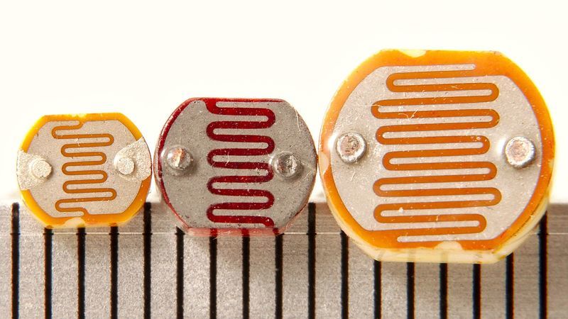
一些基本统计数据:这些统计数据用于Adafruit商店中的光电管,这与PDV-P8001非常相似。几乎所有光电管的规格都略有不同,尽管它们的工作原理几乎相同。如果有数据表,您将需要参考它。
尺寸:圆形,直径5mm(0.2“)。(其他光电管的最大尺寸为12mm/0.4 “直径!”
价格:在Adafruit商店中为1.00美元
电阻范围:200KΩ(暗)到10KΩ(10勒克斯亮度)
灵敏度范围: CdS电池对400nm之间的光产生响应(紫光) )和600nm(橙色)的波长,峰值约在520nm(绿色)。
电源:几乎所有高达100V的电源,使用的功率都小于平均1mA的电流(取决于电源电压)
数据表和另一个数据表
关于使用和选择光电管的两个应用笔记,其中几乎所有这些图形均来自
您可能会遇到多个传感器的问题
如果在添加更多传感器时发现读数不一致,则表明将模拟读数电路从一个引脚切换到另一个引脚时,传感器之间会相互干扰。另一个。您可以通过延迟两次阅读并扔掉第一个来解决此问题。
有关更多信息,请参见此帖子
测量光
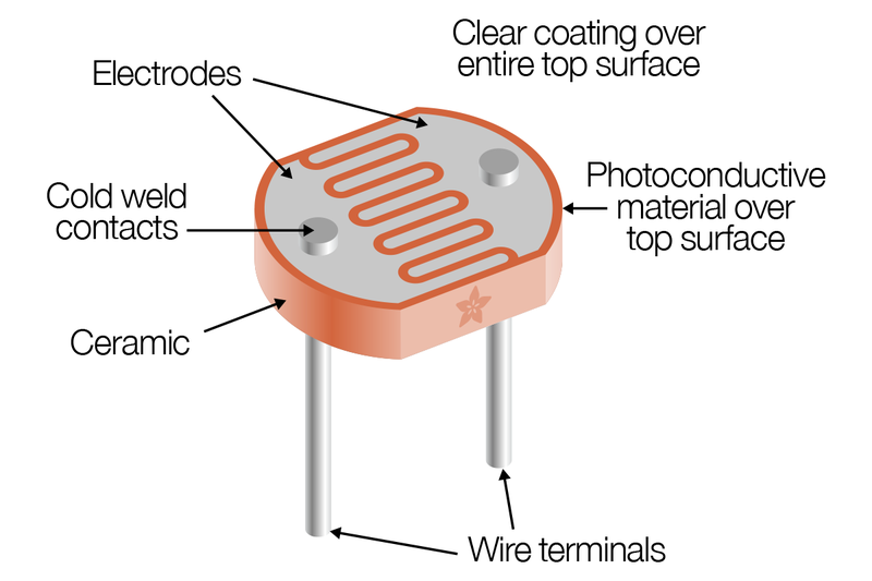
我们已经说过,光电池的电阻会随着面部暴露于更多的光而发生变化。漆黑时,传感器看起来像一个高达10MΩ的大电阻,随着光线水平的增加,电阻会降低。该图大致指示了传感器在不同光照水平下的电阻。记住每个光电管会有所不同,因此仅用作指导!
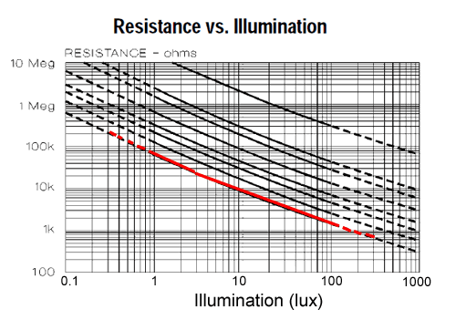
请注意,该图不是线性的,它是对数对数图!
光电管,尤其是您可能会发现的常见CdS光电管,对所有光线都不敏感。特别是它们倾向于对700nm(红色)和500nm(绿色)之间的光敏感。
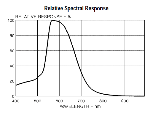
基本上,蓝光在触发传感器方面几乎不及绿/黄光!
Lux到底是什么? 大多数数据表都使用lux来表示在某些光照水平下的电阻。但是什么是lux?它不是我们倾向于用来描述亮度的方法,因此很难测量。这是来自维基百科有关该主题的文章的表格!
tr》
IlluminanceExample
0.002 lux月夜晴朗的夜空
0.2 lux紧急照明的最小设计(AS2293)。
0.27-1 lux完整在晴朗的夜晚登月
3.4 lux晴朗的天空下市民暮光的黑暗极限
50 lux家庭起居室
80 lux走廊/厕所
100 lux阴暗的日子
300-500 lux晴天时的日出或日落。
1,000 lux阴天;典型的电视演播室照明
10,000-25,000 lux全日光(非直射阳光)
32,000-130,000 lux 直射阳光
测试光电管
确定光电管工作方式的最简单方法是将电阻测量模式下的万用表连接到两条引线,并查看在用传感器遮蔽传感器时电阻如何变化您的手,关闭灯等。由于电阻变化很大,因此自动量程表在这里非常有效。否则,只需确保在“放弃”之前尝试在1MΩ和1KΩ之间尝试不同的范围。
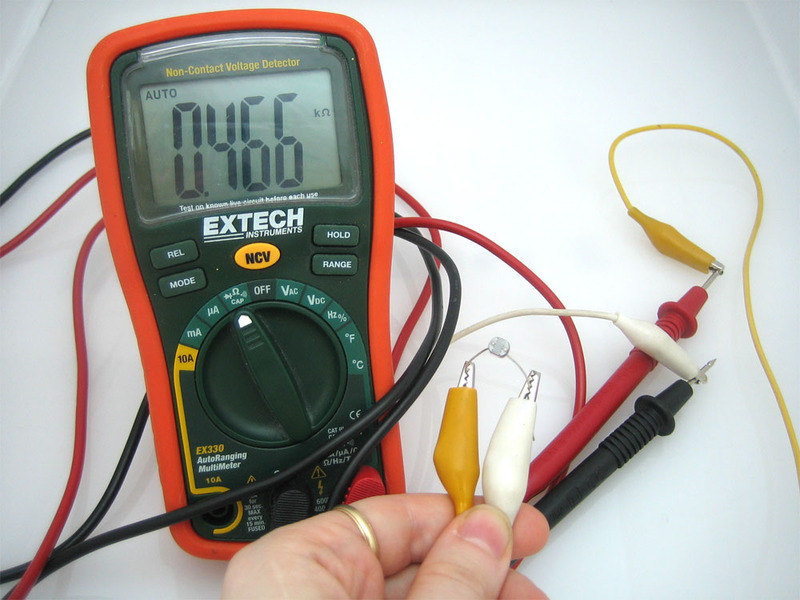
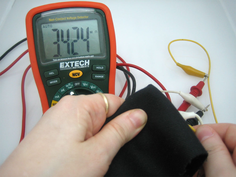
div》连接光电管
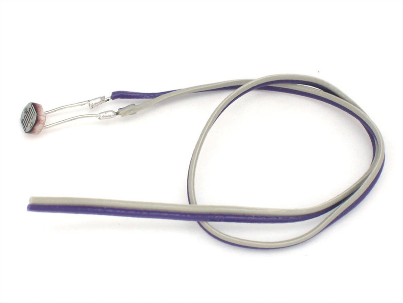
由于光电管基本上是电阻器,因此它们是无极性的。这意味着您可以“以任何一种方式”将它们连接起来,它们会正常工作!
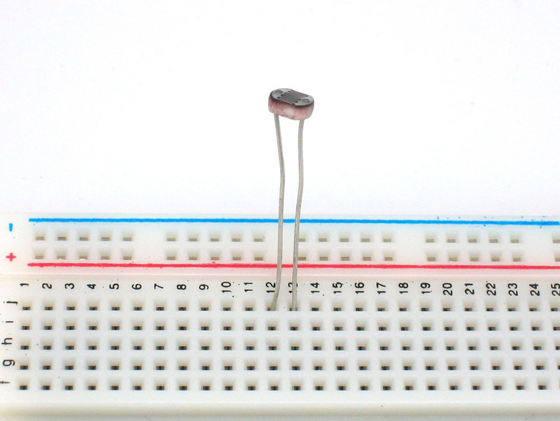
光电管非常坚固,您可以轻松地将其焊接,夹住引线,将它们插入面包板,使用鳄鱼夹等。您应该采取的措施是避免将导线直接弯曲在epoxi传感器上,因为如果弯曲得太多,它们可能会折断。
使用光电管
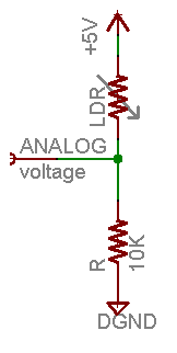
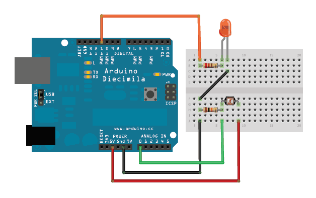
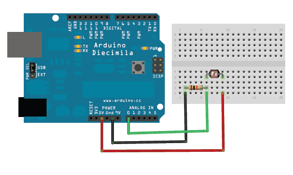
模拟电压读数方法最简单的测量电阻式传感器的方法是将一端连接到电源,另一端连接到下拉电阻到地。然后将固定下拉电阻器和可变光电管电阻器之间的点连接到微控制器的模拟输入,例如Arduino(如图所示)

i》
在此示例中,我显示的是5V电源,但请注意,将其与3.3v电源一样容易使用。在这种配置下,模拟电压读数的范围为0V(接地)至大约5V(或与电源电压大致相同)。
工作原理是,随着光电管电阻的减小,光电管和下拉电阻的总电阻从600KΩ以上降至10KΩ。这意味着流过两个电阻的电流增加,这又导致固定的10KΩ电阻两端的电压增加。
环境光,如……环境光(勒克斯)光电管电阻(Ω)LDR + R(Ω)通过LDR + R Rth上的电流
暗淡走廊0.1 lux600KΩ610KΩ0.008 mA0.1 V
月夜1 lux70KΩ80KΩ0.07 mA0.6 V
暗室10 lux10KΩ20KΩ0.25 mA2.5 V
阴暗天/明亮房间100 lux1.5KΩ11.5KΩ0.43 mA4.3 V
阴天1000 lux300Ω10.03KΩ0.5 mA5V
该表根据传感器的光/电阻(带有5V电源和10K)显示了近似的模拟电压 Ω下拉电阻。
如果您打算将传感器安装在亮区域并使用10KΩ下拉电阻,它会迅速饱和。这意味着它将达到5V的“上限”,并且无法区分有点亮和非常亮。在这种情况下,应将10KΩ下拉电阻替换为1KΩ下拉电阻。在这种情况下,它也将无法检测暗级差异,但将能够更好地检测亮光差异。这是一个必须权衡的折衷方案。
您还可以使用“ Axel Benz”公式,首先用万用表测量最小和最大电阻值,然后通过以下方法找到电阻器值:Pull-Down -Resistor = squareroot(Rmin * Rmax),这将为您提供更好的范围计算
环境光,如……环境光(lux)光电管电阻(?)LDR + R(?)通过LDR + R R上的电压
月夜1 lux70KΩ71KΩ0.07 mA0.1 V
暗室10 lux10KΩ11KΩ0.45 mA0.5 V
黑暗的阴天/明亮的房间100 lux1.5KΩ2.5KΩ2 mA2.0 V
阴天1000 lux300Ω1.3KΩ3.8 mA3.8 V
日光充足10,000 lux100Ω1.1KΩ4.5 mA4.5 V
该表基于传感器的光/电阻(带有5V电源和1K下拉电阻)显示了近似模拟电压。
请注意,我们的方法不提供相对于亮度的线性电压!而且,每个传感器都将不同。随着光强度的增加,即使电阻降低,模拟电压也会升高:
Vo = Vcc(R/(R + Photocell))
也就是说,电压与光电池电阻的 反 成正比,而光电池电阻又与光强度成反比。
Arduino代码
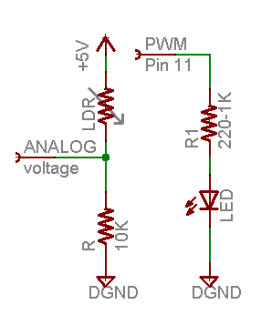
简单的使用演示 此草图将采用模拟电压读数,并以此来确定红色LED的亮度。它越黑,LED越亮!请记住,LED必须连接到PWM引脚才能起作用,在本示例中,我使用引脚11。
i》
这些示例假设您知道一些基本的Arduino编程。如果您不这样做,也许花一些时间在Arduino教程中回顾基础知识?
下载:file
复制代码
/* Photocell simple testing sketch.
Connect one end of the photocell to 5V, the other end to Analog 0.
Then connect one end of a 10K resistor from Analog 0 to ground
Connect LED from pin 11 through a resistor to ground
For more information see http://learn.adafruit.com/photocells */
int photocellPin = 0; // the cell and 10K pulldown are connected to a0
int photocellReading; // the analog reading from the sensor divider
int LEDpin = 11; // connect Red LED to pin 11 (PWM pin)
int LEDbrightness; //
void setup(void) {
// We‘ll send debugging information via the Serial monitor
Serial.begin(9600);
}
void loop(void) {
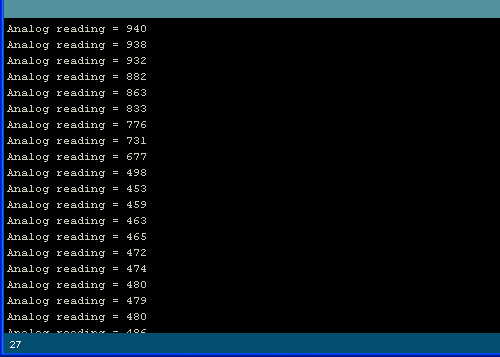
photocellReading = analogRead(photocellPin);
Serial.print(“Analog reading = ”);
Serial.println(photocellReading); // the raw analog reading
// LED gets brighter the darker it is at the sensor
// that means we have to -invert- the reading from 0-1023 back to 1023-0
photocellReading = 1023 - photocellReading;
//now we have to map 0-1023 to 0-255 since thats the range analogWrite uses
LEDbrightness = map(photocellReading, 0, 1023, 0, 255);
analogWrite(LEDpin, LEDbrightness);
delay(100);
} /* Photocell simple testing sketch.
Connect one end of the photocell to 5V, the other end to Analog 0.
Then connect one end of a 10K resistor from Analog 0 to ground
Connect LED from pin 11 through a resistor to ground
For more information see http://learn.adafruit.com/photocells */
int photocellPin = 0; // the cell and 10K pulldown are connected to a0
int photocellReading; // the analog reading from the sensor divider
int LEDpin = 11; // connect Red LED to pin 11 (PWM pin)
int LEDbrightness; //
void setup(void) {
// We’ll send debugging information via the Serial monitor
Serial.begin(9600);
}
void loop(void) {
photocellReading = analogRead(photocellPin);
Serial.print(“Analog reading = ”);
Serial.println(photocellReading); // the raw analog reading
// LED gets brighter the darker it is at the sensor
// that means we have to -invert- the reading from 0-1023 back to 1023-0
photocellReading = 1023 - photocellReading;
//now we have to map 0-1023 to 0-255 since thats the range analogWrite uses
LEDbrightness = map(photocellReading, 0, 1023, 0, 255);
analogWrite(LEDpin, LEDbrightness);
delay(100);
}
您可能要根据要检测的光强范围尝试不同的下拉电阻!
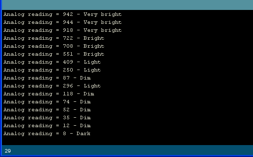
模拟光测量的简单代码该代码不执行任何操作计算时,它只是定性地打印出它解释为光量的信息。对于大多数项目,这几乎就是所有需要的东西!

下载:文件
复制代码
/* Photocell simple testing sketch.
Connect one end of the photocell to 5V, the other end to Analog 0.
Then connect one end of a 10K resistor from Analog 0 to ground
For more information see http://learn.adafruit.com/photocells */
int photocellPin = 0; // the cell and 10K pulldown are connected to a0
int photocellReading; // the analog reading from the analog resistor divider
void setup(void) {
// We‘ll send debugging information via the Serial monitor
Serial.begin(9600);
}
void loop(void) {
photocellReading = analogRead(photocellPin);
Serial.print(“Analog reading = ”);
Serial.print(photocellReading); // the raw analog reading
// We’ll have a few threshholds, qualitatively determined
if (photocellReading 《 10) {
Serial.println(“ - Dark”);
} else if (photocellReading 《 200) {
Serial.println(“ - Dim”);
} else if (photocellReading 《 500) {
Serial.println(“ - Light”);
} else if (photocellReading 《 800) {
Serial.println(“ - Bright”);
} else {
Serial.println(“ - Very bright”);
}
delay(1000);
} /* Photocell simple testing sketch.
Connect one end of the photocell to 5V, the other end to Analog 0.
Then connect one end of a 10K resistor from Analog 0 to ground
For more information see http://learn.adafruit.com/photocells */
int photocellPin = 0; // the cell and 10K pulldown are connected to a0
int photocellReading; // the analog reading from the analog resistor divider
void setup(void) {
// We‘ll send debugging information via the Serial monitor
Serial.begin(9600);
}
void loop(void) {
photocellReading = analogRead(photocellPin);
Serial.print(“Analog reading = ”);
Serial.print(photocellReading); // the raw analog reading
// We’ll have a few threshholds, qualitatively determined
if (photocellReading 《 10) {
Serial.println(“ - Dark”);
} else if (photocellReading 《 200) {
Serial.println(“ - Dim”);
} else if (photocellReading 《 500) {
Serial.println(“ - Light”);
} else if (photocellReading 《 800) {
Serial.println(“ - Bright”);
} else {
Serial.println(“ - Very bright”);
}
delay(1000);
}
要测试它,我从一个阳光照射(但有阴影)的房间开始,用手覆盖传感器,然后用一块遮光织物覆盖。
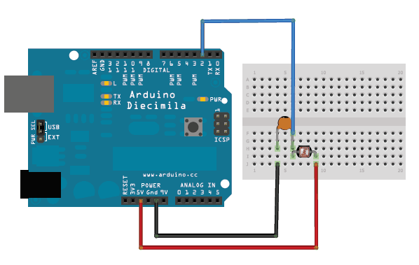
奖金!读取没有模拟引脚的光电管由于光电管基本上是电阻器,因此即使您的微控制器上没有模拟引脚(或者说您想连接的数量超过模拟输入引脚),也可以使用它们。我们这样做的方法是利用电阻器和电容器的基本电子特性。事实证明,如果您使用最初不存储电压的电容器,然后通过电阻器将其连接到电源(例如5V),则它将缓慢充电至电源电压。电阻越大,速度越慢。
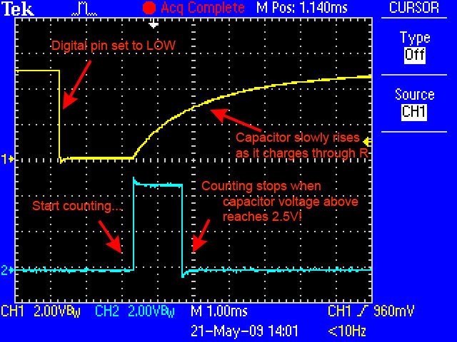
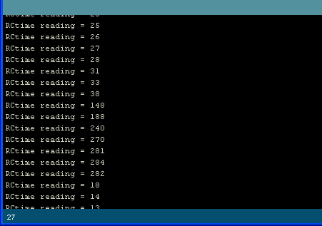
从示波器捕获的该图像显示了数字引脚(黄色)上发生的情况。蓝线表示草图何时开始计数以及何时完成计算(大约1.2毫秒后)。
这是因为电容器的作用就像一个桶,电阻的作用就像一根细管。用一根很细的管子装满水桶需要花费足够的时间,您可以通过计时将水桶装满一半的时间来确定管子的宽度。
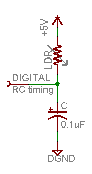
在这种情况下,我们的“桶”是一个0.1uF的陶瓷电容器。您几乎可以随意更改电容器,但时序值也会改变。对于这些光电电池,0.1uF似乎是一个不错的起点。如果要测量较亮的范围,请使用1uF电容器。如果要测量较暗的范围,请降低到0.01uF。
下载:文件
复制代码
/* Photocell simple testing sketch.
Connect one end of photocell to power, the other end to pin 2.
Then connect one end of a 0.1uF capacitor from pin 2 to ground
For more information see http://learn.adafruit.com/photocells */
int photocellPin = 2; // the LDR and cap are connected to pin2
int photocellReading; // the digital reading
int ledPin = 13; // you can just use the ‘built in’ LED
void setup(void) {
// We‘ll send debugging information via the Serial monitor
Serial.begin(9600);
pinMode(ledPin, OUTPUT); // have an LED for output
}
void loop(void) {
// read the resistor using the RCtime technique
photocellReading = RCtime(photocellPin);
if (photocellReading == 30000) {
// if we got 30000 that means we ’timed out‘
Serial.println(“Nothing connected!”);
} else {
Serial.print(“RCtime reading = ”);
Serial.println(photocellReading); // the raw analog reading
// The brighter it is, the faster it blinks!
digitalWrite(ledPin, HIGH);
delay(photocellReading);
digitalWrite(ledPin, LOW);
delay(photocellReading);
}
delay(100);
}
// Uses a digital pin to measure a resistor (like an FSR or photocell!)
// We do this by having the resistor feed current into a capacitor and
// counting how long it takes to get to Vcc/2 (for most arduinos, thats 2.5V)
int RCtime(int RCpin) {
int reading = 0; // start with 0
// set the pin to an output and pull to LOW (ground)
pinMode(RCpin, OUTPUT);
digitalWrite(RCpin, LOW);
// Now set the pin to an input and.。.
pinMode(RCpin, INPUT);
while (digitalRead(RCpin) == LOW) { // count how long it takes to rise up to HIGH
reading++; // increment to keep track of time
if (reading == 30000) {
// if we got this far, the resistance is so high
// its likely that nothing is connected!
break; // leave the loop
}
}
// OK either we maxed out at 30000 or hopefully got a reading, return the count
return reading;
} /* Photocell simple testing sketch.
Connect one end of photocell to power, the other end to pin 2.
Then connect one end of a 0.1uF capacitor from pin 2 to ground
For more information see http://learn.adafruit.com/photocells */
int photocellPin = 2; // the LDR and cap are connected to pin2
int photocellReading; // the digital reading
int ledPin = 13; // you can just use the ’built in‘ LED
void setup(void) {
// We’ll send debugging information via the Serial monitor
Serial.begin(9600);
pinMode(ledPin, OUTPUT); // have an LED for output
}
void loop(void) {
// read the resistor using the RCtime technique
photocellReading = RCtime(photocellPin);
if (photocellReading == 30000) {
// if we got 30000 that means we ‘timed out’
Serial.println(“Nothing connected!”);
} else {
Serial.print(“RCtime reading = ”);
Serial.println(photocellReading); // the raw analog reading
// The brighter it is, the faster it blinks!
digitalWrite(ledPin, HIGH);
delay(photocellReading);
digitalWrite(ledPin, LOW);
delay(photocellReading);
}
delay(100);
}
// Uses a digital pin to measure a resistor (like an FSR or photocell!)
// We do this by having the resistor feed current into a capacitor and
// counting how long it takes to get to Vcc/2 (for most arduinos, thats 2.5V)
int RCtime(int RCpin) {
int reading = 0; // start with 0
// set the pin to an output and pull to LOW (ground)
pinMode(RCpin, OUTPUT);
digitalWrite(RCpin, LOW);
// Now set the pin to an input and.。.
pinMode(RCpin, INPUT);
while (digitalRead(RCpin) == LOW) { // count how long it takes to rise up to HIGH
reading++; // increment to keep track of time
if (reading == 30000) {
// if we got this far, the resistance is so high
// its likely that nothing is connected!
break; // leave the loop
}
}
// OK either we maxed out at 30000 or hopefully got a reading, return the count
return reading;
}
CircuitPython
使用CircuitPython及其内置的模拟输入支持,很容易读取光电管看到的光量。通过将光电管连接到电路板上的模拟输入端,您可以从中读取电压,并查看其随着击中传感器的光量的变化而发生的变化。
首先将光电管连接到电路板上显示在上一页的Arduino中。您需要使用 10千欧电阻器电路设置相同的分压器,并将输出馈送到板上的任何模拟输入(请注意,没有模拟输入的读取光电管的特殊方法不是
这是将光电管连接到Feather M0的示例:
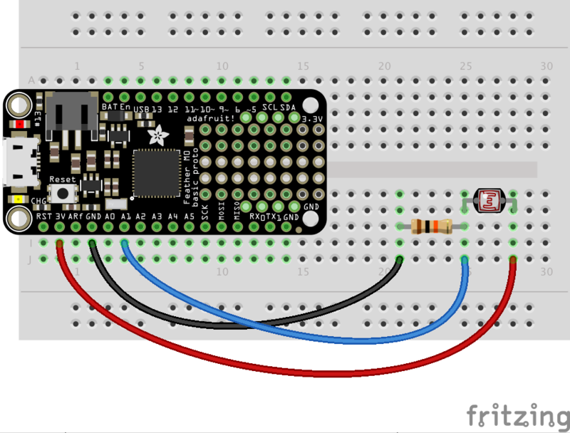
板卡3.3V 到光电管的单腿 》(与哪条腿无关)。请注意,您要使用板上的电压,该电压与最大模拟输入电压相对应。对于Feather板,此电压为3.3V,但对于其他板,该电压可能更高或更低-请务必咨询您的电路板文档。
10千欧电阻器
板GND 到10千欧电阻器的另一端。
》
板A1 (或任何其他模拟输入)连接到光电管和10千欧姆电阻的连接处。
下一步,连接到电路板的串行REPL,这样您就可以在CircuitPython上运行》》》 提示。
现在导入电路板和模拟 》允许您读取模拟输入的模块。确保还阅读了CircuitPython模拟I/O指南,以获取更多有关使用模拟输入的背景信息!
下载:文件
复制代码
import board
import analogio import board
import analogio
为连接到光电管的A1引脚创建模拟输入,电阻连接点:
下载:文件
复制代码
photocell = analogio.AnalogIn(board.A1) photocell = analogio.AnalogIn(board.A1)
在这一点上,您可以读取value属性以读取光电管看到的光。尝试:
下载:文件
复制代码
photocell.value photocell.value
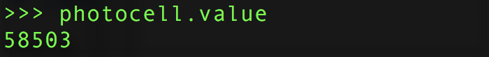
尝试用手遮盖光电管以阻挡可见光并再次读取该值:
下载:文件
复制代码
photocell.value photocell.value
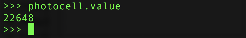
请注意,值已更改!当传感器看到的光线较少时,该值会减小。传感器看到的光线越多,该值越高。
您可能会想,可能的值范围是多少?事实证明,对于CircuitPython中的模拟输入,最大值范围是0到65535(或最大16位无符号整数值)。如果您在光电池上发出非常明亮的光,您可能会看到一个接近65k的值,如果完全阻塞了传感器,您可能会看到一个接近0的值。
如果您好奇,还可以转换取决于照射到传感器的光量多少,此值将变为更高或更低的电压。让我们做一个函数来做到这一点:
下载:文件
复制代码
def analog_voltage(adc):
return adc.value / 65535 * adc.reference_voltage
volts = analog_voltage(photocell)
print(‘Photocell voltage: {0}V’.format(volts)) def analog_voltage(adc):
return adc.value / 65535 * adc.reference_voltage
volts = analog_voltage(photocell)
print(‘Photocell voltage: {0}V’.format(volts))
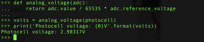
酷!请注意,随着击中光电管的光的增加,电压增加到接近3.3伏。如果将光电管盖好并读取电压,您会发现它跌落到0伏附近。
您可以使用原始值或电压来检查有多少光照射到光电管上。两者都将与照射到传感器的光量成比例地变化。
这是一个完整的程序,可以读取光电管的值并每秒打印一次值和电压。将其另存为 main.py ,然后打开串行输出以查看打印的值。尝试将光照射到传感器上或将其遮盖起来,以查看值和电压如何变化!
下载:文件
复制代码
import time
import board
import analogio
# Initialize analog input connected to photocell.
photocell = analogio.AnalogIn(board.A1)
# Make a function to convert from analog value to voltage.
def analog_voltage(adc):
return adc.value / 65535 * adc.reference_voltage
# Main loop reads value and voltage every second and prints them out.
while True:
# Read the value, then the voltage.
val = photocell.value
volts = analog_voltage(photocell)
# Print the values:
print(‘Photocell value: {0} voltage: {1}V’.format(val, volts))
# Delay for a second and repeat!
time.sleep(1.0) import time
import board
import analogio
# Initialize analog input connected to photocell.
photocell = analogio.AnalogIn(board.A1)
# Make a function to convert from analog value to voltage.
def analog_voltage(adc):
return adc.value / 65535 * adc.reference_voltage
# Main loop reads value and voltage every second and prints them out.
while True:
# Read the value, then the voltage.
val = photocell.value
volts = analog_voltage(photocell)
# Print the values:
print(‘Photocell value: {0} voltage: {1}V’.format(val, volts))
# Delay for a second and repeat!
time.sleep(1.0)
这就是使用CircuitPython使用模拟输入读取光电管的全部内容!
责任编辑:wv
-
光电管
+关注
关注
0文章
51浏览量
13277
发布评论请先 登录
光电二极管(PD)补充问题解答
雪崩光电二极管(APD)的常见问题汇总与解答

光传感器中的光电二极管和光电晶体管介绍

圣邦微电子SGM41299C如何实现温控环路热平衡

LUMAWISE ALR AA 2000EL光电控制器技术解析与应用指南
基于ALR 11000 Zhaga数字光电管的技术解析与应用设计
APD雪崩光电二极管的使用方法及核心信息讲解
耐辐射光电晶体管密封光耦合器 skyworksinc

密封表面贴装光电晶体管光耦合器 skyworksinc
光电晶体管密封表面贴装光耦合器 skyworksinc
耐辐射、光电晶体管光耦合器 skyworksinc
光电晶体管光耦合器 skyworksinc
用于混合组装的微型光电晶体管光耦合器 skyworksinc
光电晶体管密封光耦合器 skyworksinc


评论