 声音响应Cheap Ir Led Strip的制作

耗材:
1。明显带有电源
3。 Ir Emitter领导
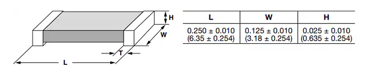
4。电阻
5。编程电缆
6。 arduino ide
7。烙铁(一些基本的焊接)
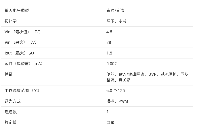
8。 7805 ic(用于使用led电源作为esp电源)
9。步骤1:准备Esp
首先,将Nodemcu与计算机或笔记本电脑连接。
现在安装nodemcu(使用谷歌搜索)的驱动程序。
打开后,Arduino IDE(当然,您需要下载并安装它)单击Arduino工具栏上的“工具”,然后单击“木板”选择“Board Manager”并搜索esp8266安装(需要一些时间才能完成)
现在,从中选择“素描” Arduino工具栏选择“包含库”,然后选择“管理库”,搜索“ IRremoteESP8266”并安装
现在,仅通过“工具”完成配置需要转到“主板”,选择“NodeMcu 1.0(ESP 12-E)”或其他版本的ESP8266。
步骤2:准备和测试IR LED
首先,我们需要安装
转到此处
标识您的led灯带,无论是24键还是44键(更大的一个)遥控器
以获取遥控器代码在这里
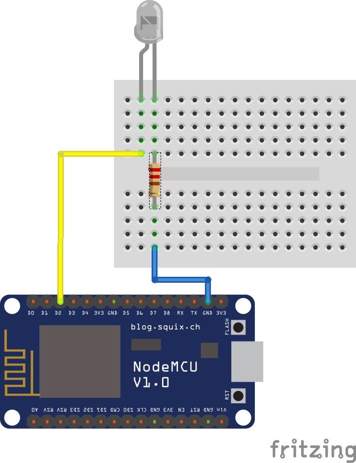
安装库后,我们ed通过按图所示连接IR LED来准备我们的IR LED。在其上连接IR LED,然后上传以下草图并将IR LED指向控制器。 LED灯条应闪烁(打开和关闭)。//可同时使用24和44键的遥控器。
HERE是执行此操作的代码。
#define IR_OFF 0xF740BF //Resective ir codes in 32 bits
#define IR_ON 0xF7C0
#includeIRsend irsend(4); // IR pin
void setup() {
irsend.begin();
}
void loop() {
irsend.sendNEC(IR_ON, 32);
delay(5000);
irsend.sendNEC(IR_OFF, 32);
delay(5000);
}
步骤3:接线和准备麦克风
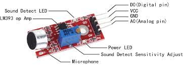
我们将仅使用Espe8266 A0的模拟引脚作为输入作为模拟信号,并使用它来触发基于声音的红外信号
将Out Pin连接到a0
将5V连接到Vin(AS节点mcu没有5v输出)
就是这样,我们将对准连接的IR LED D2引脚连接到LED灯条的接收器。
a
步骤4:上传代码并准备就绪
#include
#include
#define microphonePin A0
int sound;
int sound1;
const int irPin = 4; //d2IRsend irsend(irPin);void setup() {
Serial.begin(9600);
pinMode(microphonePin, INPUT);
pinMode(irPin, OUTPUT);}
// ir led Codes
#define IR_BPlus 0xFF3AC5 //
#define IR_BMinus 0xFFBA45 //
#define IR_ON 0xFF827D //
#define IR_OFF 0xFF02FD //
#define IR_R 0xFF1AE5 //
#define IR_G 0xFF9A65 //
#define IR_B 0xFFA25D //
#define IR_W 0xFF22DD //
#define IR_B1 0xFF2AD5 //
#define IR_B2 0xFFAA55 //
#define IR_B3 0xFF926D //
#define IR_B4 0xFF12ED //
#define IR_B5 0xFF0AF5 //
#define IR_B6 0xFF8A75 //
#define IR_B7 0xFFB24D //
#define IR_B8 0xFF32CD //
#define IR_B9 0xFF38C7 //
#define IR_B10 0xFFB847 //
#define IR_B11 0xFF7887 //
#define IR_B12 0xFFF807 //
#define IR_B13 0xFF18E7 //
#define IR_B14 0xFF9867 //
#define IR_B15 0xFF58A7 //
#define IR_B16 0xFFD827 //
#define IR_UPR 0xFF28D7 //
#define IR_UPG 0xFFA857 //
#define IR_UPB 0xFF6897 //
#define IR_QUICK 0xFFE817 //
#define IR_DOWNR 0xFF08F7 //
#define IR_DOWNG 0xFF8877 //
#define IR_DOWNB 0xFF48B7 //
#define IR_SLOW 0xFFC837 //
#define IR_DIY1 0xFF30CF //
#define IR_DIY2 0xFFB04F //
#define IR_DIY3 0xFF708F //
#define IR_AUTO 0xFFF00F //
#define IR_DIY4 0xFF10EF //
#define IR_DIY5 0xFF906F //
#define IR_DIY6 0xFF50AF //
#define IR_FLASH 0xFFD02F //
#define IR_JUMP3 0xFF20DF //
#define IR_JUMP7 0xFFA05F //
#define IR_FADE3 0xFF609F //
#define IR_FADE7 0xFFE01F //
void loop() {
sound = analogRead(microphonePin); // getting input audio signal reading
Serial.print(sound); // input audio signal readings to Serial display
Serial.print(“ ”);
if (sound 》 415)
{
sound1 = map(sound, 415, 750, 140, 255); // mapping higher frequency values which are above offset to the scale of 150 - 255
}
else if (sound 》 340 && sound 《 415) // keeping offset reading to zero scale..here offset value in the range of 340 - 415(offset value at 1.45v) 。.its depends on componets used in circuit.。
{
sound1 = map(sound, 340, 415, 0, 9);
}
else if (sound 《 340)
{
sound1 = map(sound, 0, 340, 10, 139); // keeping below offset readings to scale of 1-139.。
}
if (sound1 》 240)
{
irsend.sendNEC(IR_FLASH, 32);
irsend.sendNEC(IR_QUICK, 32);
irsend.sendNEC(IR_QUICK, 32);
irsend.sendNEC(IR_QUICK, 32);
irsend.sendNEC(IR_QUICK, 32);
irsend.sendNEC(IR_QUICK, 32);
irsend.sendNEC(IR_QUICK, 32);
}
else if ((sound1) 》 200)
{
irsend.sendNEC(IR_G, 32);
irsend.sendNEC(IR_B, 32);
delay(120);}
else if (sound1 》 160)
{
irsend.sendNEC(IR_R, 32);
irsend.sendNEC(IR_B, 32);
delay(120);
}
else if (sound1 》 120)
{
irsend.sendNEC(IR_B, 32);
delay(120);
}
else if (sound1 》 80)
{
irsend.sendNEC(IR_B, 32);
delay(120);
}
else if (sound1 》 40)
{
irsend.sendNEC(IR_G, 32);
delay(120);
}
else if (sound1 》 10)
{
irsend.sendNEC(IR_R, 32);
delay(120);}
else耗材:
1。明显带有电源
2的LED灯条。 esp8266/节点mcu
3。 Ir Emitter领导
4。电阻
5。编程电缆
6。 arduino ide
7。烙铁(一些基本的焊接)
8。 7805 ic(用于使用led电源作为esp电源)
9。步骤1:准备Esp
首先,将Nodemcu与计算机或笔记本电脑连接。
现在安装nodemcu(使用谷歌搜索)的驱动程序。
打开后,Arduino IDE(当然,您需要下载并安装它)单击Arduino工具栏上的“ 工具”,然后单击“ 木板”选择“ Board Manager ”并搜索esp8266安装(需要一些时间才能完成)
现在,从中选择“ 素描” Arduino工具栏选择“包含库”,然后选择“管理库”,搜索“ IRremoteESP8266”并安装
现在,仅通过“ 工具”完成配置需要转到“ 主板”,选择“ NodeMcu 1.0(ESP 12-E)”或其他版本的 ESP8266 。
步骤2:准备和测试IR LED
首先,我们需要安装
转到此处
标识您的led灯带,无论是24键还是44键(更大的一个)遥控器
以获取遥控器代码在这里
安装库后,我们ed通过按图所示连接IR LED来准备我们的IR LED。在其上连接IR LED,然后上传以下草图并将IR LED指向控制器。 LED灯条应闪烁(打开和关闭)。//可同时使用24和44键的遥控器。
HERE是执行此操作的代码。
#define IR_OFF 0xF740BF //Resective ir codes in 32 bits
#define IR_ON 0xF7C0
#include
IRsend irsend(4); // IR pin
void setup() {
irsend.begin();
}
void loop() {
irsend.sendNEC(IR_ON, 32);
delay(5000);
irsend.sendNEC(IR_OFF, 32);
delay(5000);
}
步骤3:接线和准备麦克风
我们将仅使用Espe8266 A0的模拟引脚作为输入作为模拟信号,并使用它来触发基于声音的红外信号
将Out Pin连接到a0
将5V连接到Vin(AS节点mcu没有5v输出)
就是这样,我们将对准连接的IR LED D2引脚连接到LED灯条的接收器。
a
步骤4:上传代码并准备就绪
#include
#include
#define microphonePin A0
int sound;
int sound1;
const int irPin = 4; //d2IRsend irsend(irPin);void setup() {
Serial.begin(9600);
pinMode(microphonePin, INPUT);
pinMode(irPin, OUTPUT);}
// ir led Codes
#define IR_BPlus 0xFF3AC5 //
#define IR_BMinus 0xFFBA45 //
#define IR_ON 0xFF827D //
#define IR_OFF 0xFF02FD //
#define IR_R 0xFF1AE5 //
#define IR_G 0xFF9A65 //
#define IR_B 0xFFA25D //
#define IR_W 0xFF22DD //
#define IR_B1 0xFF2AD5 //
#define IR_B2 0xFFAA55 //
#define IR_B3 0xFF926D //
#define IR_B4 0xFF12ED //
#define IR_B5 0xFF0AF5 //
#define IR_B6 0xFF8A75 //
#define IR_B7 0xFFB24D //
#define IR_B8 0xFF32CD //
#define IR_B9 0xFF38C7 //
#define IR_B10 0xFFB847 //
#define IR_B11 0xFF7887 //
#define IR_B12 0xFFF807 //
#define IR_B13 0xFF18E7 //
#define IR_B14 0xFF9867 //
#define IR_B15 0xFF58A7 //
#define IR_B16 0xFFD827 //
#define IR_UPR 0xFF28D7 //
#define IR_UPG 0xFFA857 //
#define IR_UPB 0xFF6897 //
#define IR_QUICK 0xFFE817 //
#define IR_DOWNR 0xFF08F7 //
#define IR_DOWNG 0xFF8877 //
#define IR_DOWNB 0xFF48B7 //
#define IR_SLOW 0xFFC837 //
#define IR_DIY1 0xFF30CF //
#define IR_DIY2 0xFFB04F //
#define IR_DIY3 0xFF708F //
#define IR_AUTO 0xFFF00F //
#define IR_DIY4 0xFF10EF //
#define IR_DIY5 0xFF906F //
#define IR_DIY6 0xFF50AF //
#define IR_FLASH 0xFFD02F //
#define IR_JUMP3 0xFF20DF //
#define IR_JUMP7 0xFFA05F //
#define IR_FADE3 0xFF609F //
#define IR_FADE7 0xFFE01F //
void loop() {
sound = analogRead(microphonePin); // getting input audio signal reading
Serial.print(sound); // input audio signal readings to Serial display
Serial.print(“ ”);
if (sound 》 415)
{
sound1 = map(sound, 415, 750, 140, 255); // mapping higher frequency values which are above offset to the scale of 150 - 255
}
else if (sound 》 340 && sound 《 415) // keeping offset reading to zero scale..here offset value in the range of 340 - 415(offset value at 1.45v) 。.its depends on componets used in circuit.。
{
sound1 = map(sound, 340, 415, 0, 9);
}
else if (sound 《 340)
{
sound1 = map(sound, 0, 340, 10, 139); // keeping below offset readings to scale of 1-139.。
}
if (sound1 》 240)
{
irsend.sendNEC(IR_FLASH, 32);
irsend.sendNEC(IR_QUICK, 32);
irsend.sendNEC(IR_QUICK, 32);
irsend.sendNEC(IR_QUICK, 32);
irsend.sendNEC(IR_QUICK, 32);
irsend.sendNEC(IR_QUICK, 32);
irsend.sendNEC(IR_QUICK, 32);
}
else if ((sound1) 》 200)
{
irsend.sendNEC(IR_G, 32);
irsend.sendNEC(IR_B, 32);
delay(120);}
else if (sound1 》 160)
{
irsend.sendNEC(IR_R, 32);
irsend.sendNEC(IR_B, 32);
delay(120);
}
else if (sound1 》 120)
{
irsend.sendNEC(IR_B, 32);
delay(120);
}
else if (sound1 》 80)
{
irsend.sendNEC(IR_B, 32);
delay(120);
}
else if (sound1 》 40)
{
irsend.sendNEC(IR_G, 32);
delay(120);
}
else if (sound1 》 10)
{
irsend.sendNEC(IR_R, 32);
delay(120);}
else
{
irsend.sendNEC(IR_FADE7, 32);
delay(120);
} Serial.println(sound1);
delay(50);
}
{
irsend.sendNEC(IR_FADE7, 32);
delay(120);
} Serial.println(sound1);
delay(50);
}
责任编辑:wv
-
led
+关注
关注
244文章
24724浏览量
692493 -
Arduino
+关注
关注
190文章
6527浏览量
197459
发布评论请先 登录
如何查看小智是否成功进入声音设置?
剖析MAX25614:为汽车驾驶监控系统赋能的IR LED/VCSEL驱动器
探索MAX25614:汽车驾驶员监测系统的理想IR LED/VCSEL驱动器
汽车驾驶员监控系统的得力助手:MAX25614系列IR LED/VCSEL驱动器
MAX25614系列:汽车驾驶员监测系统的理想IR LED/VCSEL驱动器
梦之墨蓝牙音响工程实践课程开启电子专业实训新体验
IR21592/IR21593:调光镇流器控制IC的技术解析
IR LED 选型手册2025年最新版
探索POWERZ EXTREME STRIP/Ten60:60A高功率系统的卓越之选
Vishay Power Metal Strip®电阻器技术解析与应用指南
Vishay WSLF3222 Power Metal Strip® 电阻器技术解析与应用指南

蔚来天琴沉浸声音响系统如何实现极致听觉体验
瑞声科技与英国音响品牌Naim Audio达成深度合作
TPS54200/TPS54201同步降压LED驱动器数据手册总结


评论