 Silicon Lab bSi5372/71主要特性及电路图解析

Silicon Lab公司的Si5372/71是单个PLL抖动衰减时钟,集成了两个外部(A级)和内部(J级)基准和该公司最新第四代DSPLL技术,以提供下一代相干光学应用的所需的性能.集成的基准不易受声发射影响,从而消除了外接晶振,从而节省了空间和成本.多达4个输出,满足高速整数模式,在相位抖动45fs-rms(1MHz-40MHz)高达2.75GHz.每个输出还可以配置成multiSynth模式任何频率输出,只要所增加频率灵活性是需要的,比如时钟正向误差修正(FEC)还能提供90 fs-rms典型的相位抖动(12 kHz-20 MHz).Si5372/71还具有低到0.001ppb步控制的DCO控制,并能锁住间隙时钟输入.输入频率范围,差分为8 kHz- 750 MHz, LVCMOS为8 kHz - 250 MHz,高速整数模式的最大输出频率2.75GHz,典型抖动45 fs-rms(1 MHz–40 MHz);Multisynth模式的最大输出频率717.5 MHz,典型抖动为90 fs RMS(12 kHz–20 MHz).器件满足以下规范ITU-T G.8262 (SyncE) EEC Options 1 and 2和ITU-T G.8262.1 (Enhanced SyncE) eEEC.主要用在相干光线路卡和模块(100G/400G/600G)以及高速数据转换器时钟.本文介绍了Si5372/71主要特性,功能框图,以及评估板Si5372 -EVB主要特性,功能框图,电路图和材料清单.
The Si5372/71 are single-PLL jitter attenuating clocks with both external (Grade A)and internal (Grade J) reference and Silicon Labs’ latest 4th generation DSPLL technologyto deliver the performance requirements of next generation coherent opticalapplications. The integrated reference is less susceptible to acoustic emissions andeliminates the need for external crystals that take up extra space and cost.
Up to four outputs can be assigned to high-speed integer mode capable of up to2.75 GHz at 45 fs-rms typical phase jitter (1 MHz–40 MHz). Each output may also beconfigured as multiSynth mode any-frequency outputs when added frequency flexibilityis required, such as clocking Forward Error Correction (FEC) while still delivering90 fs-rms typical phase jitter (12 kHz-20 MHz). The Si5372/71 also feature DCOcontrol with as low as 0.001 ppb step control and is able to lock to gapped clock inputs.
These devices are available with factory programming or can be programmedvia a serial interface with in-circuit programmable non-volatile memory (NVM) so thatthey always power up with a known frequency configuration. The loop filter is fullyintegrated on-chip eliminating the risk of potential noise coupling associated with discretesolutions. Programming the Si5372/71 is made easy with Silicon Labs’ Clock-Builder Pro™.
The Si5371 has two outputs, and the Si5372 has four outputs, with external crystal versions (Grade A) available in 7 mm x 7 mm 44-QFN packages and internal reference versions (Grade J) available in 7 mm x 7 mm 44-LGA packages.
Si5372主要特性:
• Supports High-speed line side clocks up to2.75 GHz
• Generates any output frequency in any formatfrom any input frequency
• Integrated reference (Grade J)
• Better acoustic emissions immunity
• Significantly smaller board area
• Enhanced hitless switching minimizes outputphase transients (0.2 ns typ)
• Input frequency range
• Differential: 8 kHz to 750 MHz
• LVCMOS: 8 kHz to 250 MHz
• High-speed Integer mode
• 45 fs-rmsTyp Jitter (1 MHz–40 MHz)
• Maximum output Frequency of 2.75 GHz
• Multisynth mode
• 90 fs RMS Typ Jitter (12 kHz–20 MHz)
• Maximum output Frequency of 717.5 MHz
• Meets requirements of:
• ITU-T G.8262 (SyncE) EEC Options 1 and 2
• ITU-T G.8262.1 (Enhanced SyncE) eEEC
• Status monitoring
• Si5372: 4 input, 4 output
• Si5371: 4 input, 2 output
• Drop-in compatible with Si5344H/42H
Si5372应用:
• Coherent optical line cards and modules (100G/400G/600G)
• High-speed data converter clocking
![[原创] Silicon Lab Si5372抖动衰减集成基准单PLL相干光学时钟解决方案](/uploads/allimg/190926/160002CB_0.jpg)
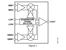
图1.Si5372框图表
评估板Si5372 –EVB
The Si5372-EVB is used for evaluating the Si5372 Any-Frequency, Any-Output, Jitter Attenuating Clock Multiplier. The Si5372 combines 4th generation DSPLL and Multisynth ™ technologies to enable any-frequency clock generation for applications that require the highest level of jitter performance. There are two different EVBs for theSi5372. There is an A grade which uses an external XTAL reference and there is a Jgrade which has an internal XTAL reference. This user guide is intended for all versionsof the Si5372 EVB.
The device grade and revision is distinguished by a white 1inch x 0.187 inch label installed in the lower left hand corner of the board. In the examplebelow, the label "SI5372J-A-EB" indicates the evaluation board has been assembledwith an Si5372 device, Grade J, Revision A, installed. (For ordering purposes only,the terms “EB” and “EVB” refer to the board and the kit respectively. For the purposeof this document, the terms are synonymous in context.)The device The Si5372-EVBhas two independent input clocks and four independent output clocks. The Si5372-EVBcan be controlled and configured using the ClockBuilderPro™ (CBPro) software tool.
评估板Si5372 -EVB主要特性:
• Si5372A-A-EB for evaluating externalXTAL version Si5372A
• Onboard 48 MHz XTAL or ReferenceSMA Inputs allow holdover mode ofoperation on the Si5372.
• Si5372J-A-EB for evaluating internal XTALversion Si5372J
• Powered from USB port or external powersupply.
• CBPro™ GUI-programmable VDD supplyallows the device to operate from 3.3, 2.5,or 1.8 V.
• CBPro GUI-programmable VDDO suppliesallow each of the ten outputs to have itsown supply voltage, selectable from 3.3,2.5, or 1.8 V.
• CBPro GUI-controlled voltage, current,and power measurements of VDD and allVDDO supplies.
• Status LEDs for power supplies andcontrol/status signals of Si5372.
• SMA connectors for input clocks, outputclocks, and optional external timingreference clock.
图2.评估板Si5372 -EVB外形图
评估板包括:
Seamless download from ClockBuilder Pro to EVB
SMA connectors for high quality measurements
No external clocks are required for free-run evaluation
Real-time power and junction temperature measurements
Access all registers, LED indicators and I/O
Most configurations can be powered by USB
![[原创] Silicon Lab Si5372抖动衰减集成基准单PLL相干光学时钟解决方案](/uploads/allimg/190926/1602016050_0.jpg)
图3.评估板Si5372 -EVB功能框图
![[原创] Silicon Lab Si5372抖动衰减集成基准单PLL相干光学时钟解决方案](/uploads/allimg/190926/16030131V_0.jpg)
图4.评估板Si5372 -EVB电路图(1)
![[原创] Silicon Lab Si5372抖动衰减集成基准单PLL相干光学时钟解决方案](/uploads/allimg/190926/160402a10_0.jpg)
图5.评估板Si5372 -EVB电路图(2)
![[原创] Silicon Lab Si5372抖动衰减集成基准单PLL相干光学时钟解决方案](/uploads/allimg/190926/160502U23_0.jpg)
图6.评估板Si5372 -EVB电路图(3)
![[原创] Silicon Lab Si5372抖动衰减集成基准单PLL相干光学时钟解决方案](/uploads/allimg/190926/160602UT_0.jpg)
图7.评估板Si5372 -EVB电路图(4)
![[原创] Silicon Lab Si5372抖动衰减集成基准单PLL相干光学时钟解决方案](/uploads/allimg/190926/160F2b95_0.jpg)
图8.评估板Si5372 -EVB电路图(5)
评估板Si5372 -EVB材料清单:
![[原创] Silicon Lab Si5372抖动衰减集成基准单PLL相干光学时钟解决方案](/uploads/allimg/190926/160P1bD_0.jpg)
![[原创] Silicon Lab Si5372抖动衰减集成基准单PLL相干光学时钟解决方案](/uploads/allimg/190926/160Z2L23_0.jpg)
![[原创] Silicon Lab Si5372抖动衰减集成基准单PLL相干光学时钟解决方案](/uploads/allimg/190926/16100350C_0.jpg)
![[原创] Silicon Lab Si5372抖动衰减集成基准单PLL相干光学时钟解决方案](/uploads/allimg/190926/161102IE_0.jpg)
![[原创] Silicon Lab Si5372抖动衰减集成基准单PLL相干光学时钟解决方案](/uploads/allimg/190926/1612014118_0.jpg)
图9.评估板Si5372A-A-EVB电路图(1)
![[原创] Silicon Lab Si5372抖动衰减集成基准单PLL相干光学时钟解决方案](/uploads/allimg/190926/161302DL_0.jpg)
图10.评估板Si5372A-A-EVB电路图(2)
![[原创] Silicon Lab Si5372抖动衰减集成基准单PLL相干光学时钟解决方案](/uploads/allimg/190926/1614024F1_0.jpg)
图11.评估板Si5372A-A-EVB电路图(3)
![[原创] Silicon Lab Si5372抖动衰减集成基准单PLL相干光学时钟解决方案](/uploads/allimg/190926/1615035I0_0.jpg)
图12.评估板Si5372A-A-EVB电路图(4)
![[原创] Silicon Lab Si5372抖动衰减集成基准单PLL相干光学时钟解决方案](/uploads/allimg/190926/1616024241_0.jpg)
图13.评估板Si5372A-A-EVB电路图(5)
评估板Si5372A-A-EVB材料清单:
![[原创] Silicon Lab Si5372抖动衰减集成基准单PLL相干光学时钟解决方案](/uploads/allimg/190926/161F25503_0.jpg)
![[原创] Silicon Lab Si5372抖动衰减集成基准单PLL相干光学时钟解决方案](/uploads/allimg/190926/161P16401_0.jpg)
![[原创] Silicon Lab Si5372抖动衰减集成基准单PLL相干光学时钟解决方案](/uploads/allimg/190926/161Z12050_0.jpg)
![[原创] Silicon Lab Si5372抖动衰减集成基准单PLL相干光学时钟解决方案](/uploads/allimg/190926/1620015929_0.jpg)
-
dsp
+关注
关注
559文章
8220浏览量
364237 -
Silicon
+关注
关注
0文章
136浏览量
39802 -
数据转换器
+关注
关注
1文章
398浏览量
30502
发布评论请先 登录
光学像差特性深度解析

PIC18F56Q71 Curiosity Nano评估套件技术解析与应用指南
NVIDIA Isaac Sim 4.5.0与lsaac Lab 2.0的安装教程
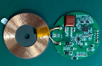
无线充电技术解析:从电磁感应到未来应用
每周推荐!电子工程师自学资料及各种电路解析
IP6808无线充电电路图解析与应用指南
MDD整流二极管的伏安特性曲线解析及应用影响
ADL5372 1500MHz至2500MHz正交调制器技术手册

华为通过BSI全球首批漏洞管理体系认证


 工商网监
工商网监
评论