 RFID和蓝牙门锁的制作

步骤1:所需的零件
必需的零件。
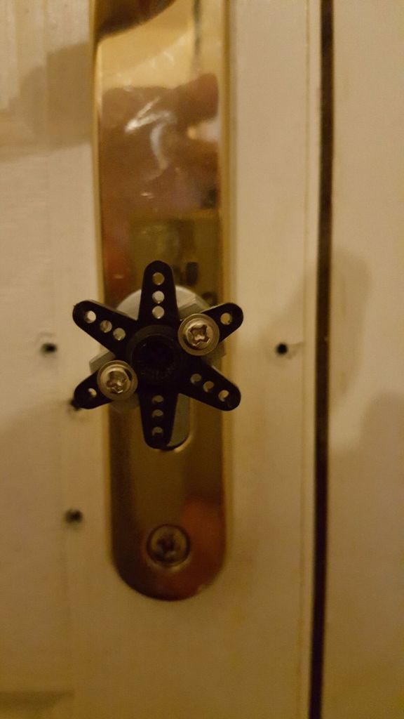
1-带拇指的门锁打开门的内部
1-Arduino Uno r3(或兼容)
1-360度伺服系统
1-HC-06蓝牙模块
1-RC522 RFID阅读器(可能是Sintron,不记得了)
1-16 x 2-4线LDC屏幕
1-RGB LED
2-220Ω电阻器
1-瞬时按动开关(从内部操作以锁定/
1-1-1kΩ电阻器
2-双后箱(1个约45mm深度,另一个约33mm深度)
跳线
电源(我打算使用2 x 9v电池,但已决定使用市电供电的9v电源,因为更可靠)
螺丝或坚固的双面胶带
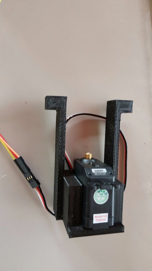
1-伺服支架(我自己设计和印刷)
** ----------------等待发货-------- ------------------- ------------ **
2-双盲板
1-12芯报警电缆的长度(长度取决于放置位置)
2-5amp模块连接器(每个12线)
** --------------------------- -------------------------------------------------- ---- **
Andriod蓝牙锁应用程序。 BTControl.apk
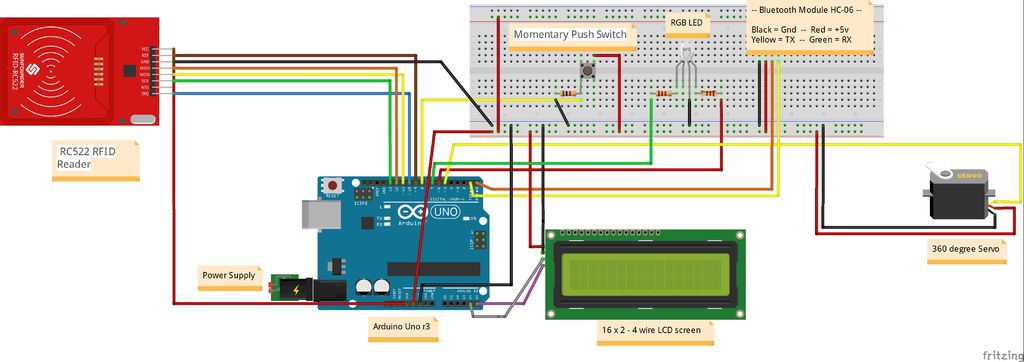
步骤2:接线
电源:
9v稳压电源(或电池)
RFID读取器:
VCC-引脚3.3v
GND-GND
重置(RST)-引脚D9
SDA(SS)-引脚D10
MOSI-引脚D11
MISO-引脚D12
SCK-引脚D13
LCD屏幕
VCC-5v
GND-GND
SDA-引脚A4
SCL-引脚A5
瞬时开关:
VCC-5v(如上所示)
GND到1kΩ电阻(如上所示)
Pin 8 arduino(如上所示)
RGB LED:
将D7的220Ω电阻接至LED引脚(红色)
将D6的220Ω电阻接至LED引脚(绿色)
公共(长线)- GND
伺服:
VCC-5v
GND-GND
信号-引脚D5
蓝牙模块:
VCC-5v
GND -GND
TX-D0(RX)
RX-D1(TX)
Fritzing图:
步骤3:Pu一起努力
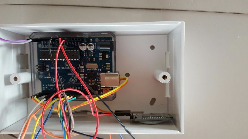
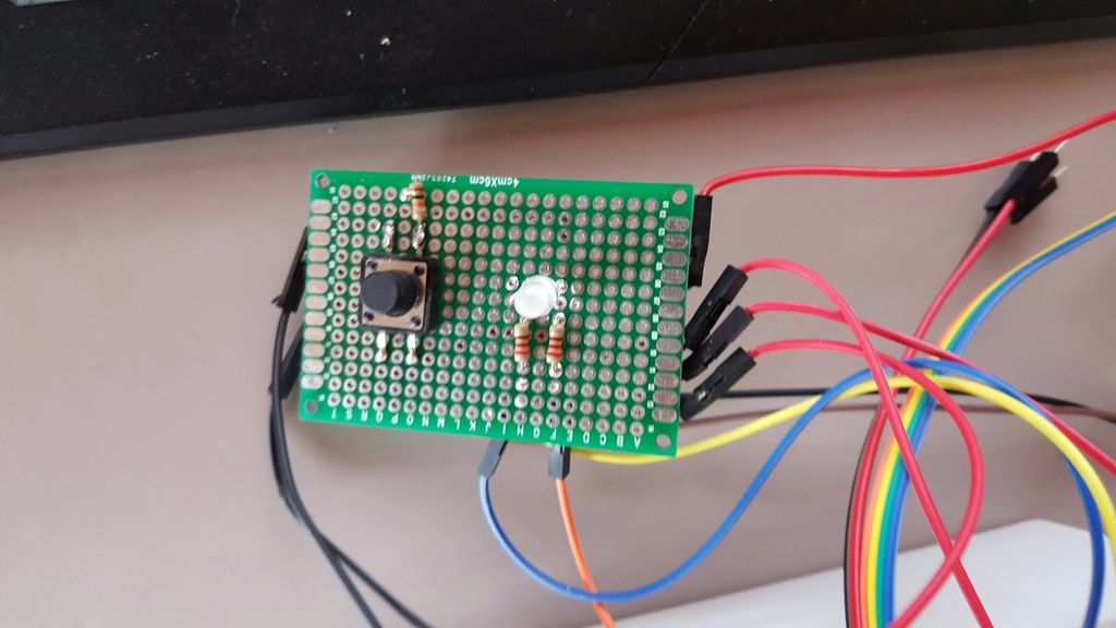
Arduino,蓝牙模块和瞬间开关+ RGB LED电路安装在45mm的底盒中。我刚刚使用Blu-Tac将它们固定在原位,因为一旦固定在墙上就不会移动。我已经将开关,LED和电阻器焊接到了电路板上,并在电路板的任何一侧创建了GND和VCC连接,还将放置一个用于12芯报警电缆的块连接器,以连接RFID和LCD屏幕到arduino。盖子上会钻2个孔,以容纳开关和引线。
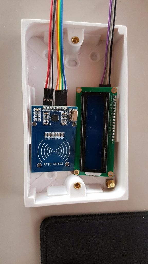
RFID和LCD屏幕安装在33mm的后盖内,并开有一个插槽,用于LCD屏幕穿过。这些将通过12芯报警电缆和模块连接器连接到arduino。
为使伺服器连接到门锁,我3D打印了一个支架,该支架将拧紧到门上并连接到门上。
步骤4:代码-(于2018年6月23日更新)
/*
* ----------------------------------------------------------------------------
* This sketch uses the MFRC522 library ; see https://github.com/miguelbalboa/rfid
* for further details and other examples.
*
* NOTE: The library file MFRC522.h has a lot of useful info. Please read it.
*
* This sketch show a simple locking mechanism using the RC522 RFID module.
* ----------------------------------------------------------------------------
* Typical pin layout used:
* -----------------------------------------------------------------------------------------
* MFRC522 Arduino Arduino Arduino Arduino Arduino
* Reader/PCD Uno Mega Nano v3 Leonardo/Micro Pro Micro
* Signal Pin Pin Pin Pin Pin Pin
* -----------------------------------------------------------------------------------------
* RST/Reset RST 9 5 D9 RESET/ICSP-5 RST
* SPI SS SDA(SS) 10 53 D10 10 10
* SPI MOSI MOSI 11 / ICSP-4 51 D11 ICSP-4 16
* SPI MISO MISO 12 / ICSP-1 50 D12 ICSP-1 14
* SPI SCK SCK 13 / ICSP-3 52 D13 ICSP-3 15
*
*/
#include
#include
#include
#include
#include
#include
#define RST_PIN 9 // Configurable, see typical pin layout above
#define SS_PIN 10
#define Green_LED 6 //pin for green “door unlocked” indicator LED
#define Red_LED 7 //pin for red “door locked” indicator LED
char array1[]=“ Swipe Your Tag”; //the string to print on the LCD
char array2[]=“ On The Reader.”;
char array3[]=“ Tag Accepted. ”;
char array4[]=“ Locking. ”;
char array5[]=“ Unlocking. ”;
int tim = 1; //the value of delay time
// initialize the library with the numbers of the interface pins
LiquidCrystal_I2C lcd(0x27,16,2); // set the LCD address to 0x27 for a 16 chars and 2 line
MFRC522 mfrc522(SS_PIN, RST_PIN); // Create MFRC522 instance.
Servo myservo;
String read_rfid;
String ok_rfid_1=“94e68de2”;
String ok_rfid_2=“f5642a50”;
String ok_rfid_3=“4249622993c81”;
int addr = 1;
int eVal = 0;
int lockPosition;
int servo_position;
int BUTTON1 = 8;
void setup() {
Serial.begin(9600); // Initialize serial communications with the PC
while (!Serial); // Do nothing if no serial port is opened (added for Arduinos based on ATMEGA32U4)
SPI.begin(); // Init SPI bus
mfrc522.PCD_Init(); // Init MFRC522 card
{
lcd.init(); //initialize the lcd
lcd.backlight(); //open the backlight
lcd.begin(16,2);
}
pinMode(Green_LED, OUTPUT); //set all input/output pins, including whether they should be high (5v) or low (ground)
pinMode(Red_LED, OUTPUT);
digitalWrite(Green_LED, LOW);
digitalWrite(Red_LED, HIGH);
pinMode(BUTTON1,INPUT);
myservo.attach(5);
lockPosition = EEPROM.read(1);
// Serial.print(EEPROM.read(1));
if(lockPosition == 1){
digitalWrite(Red_LED, LOW);
digitalWrite(Green_LED, HIGH);
}
else {
digitalWrite(Red_LED, HIGH);
digitalWrite(Green_LED, LOW);
lockUnlock();
}
swipeText();
/*
* Dump a byte array as hex values to Serial.
*/
void dump_byte_array(byte *buffer, byte bufferSize) {
read_rfid=“”;
for (byte i = 0; i 《 bufferSize; i++) {
read_rfid=read_rfid + String(buffer[i], HEX);
}
}
void lockUnlock() { // locks or unlocks door
myservo.attach(5);
if(lockPosition == 1) {
lock2();
servo_position = 0;
myservo.write(servo_position);
digitalWrite(Red_LED, HIGH);
digitalWrite(Green_LED, LOW);
delay(3000);
lockPosition = 2;
eVal = lockPosition;
EEPROM.write(1,eVal);
// Serial.print(eVal);
}
else if(lockPosition == 2) {
lock1();
servo_position = 350;
myservo.write(servo_position);
digitalWrite(Red_LED, LOW);
digitalWrite(Green_LED, HIGH);
delay(3000);
lockPosition = 1;
eVal = lockPosition;
EEPROM.write(1,eVal);
// Serial.print(eVal);
}
myservo.detach();
}
void swipeText()
{
lcd.clear(); //Clears the LCD screen and positions the cursor in the upper-left corner.
lcd.setCursor(0,0); // set the cursor to column 15, line 0
for (int positionCounter1 = 0; positionCounter1 《 15; positionCounter1++)
{
lcd.print(array1[positionCounter1]); // Print a message to the LCD.
delay(tim); //wait for 250 microseconds
}
lcd.setCursor(0,1); // set the cursor to column 15, line 1
for (int positionCounter = 0; positionCounter 《 15; positionCounter++)
{
lcd.print(array2[positionCounter]); // Print a message to the LCD.
delay(tim); //wait for 250 microseconds
}
}
void lock1()
{
lcd.clear();
lcd.setCursor(0,0);
for (int positionCounter1 = 0; positionCounter1 《 15; positionCounter1++)
{
lcd.print(array3[positionCounter1]);
delay(tim);
}
lcd.setCursor(0,1);
for (int positionCounter1 = 0; positionCounter1 《 10; positionCounter1++)
{
lcd.print(array4[positionCounter1]);
delay(tim);
}
}
void lock2()
{
lcd.clear();
lcd.setCursor(0,0);
for (int positionCounter1 = 0; positionCounter1 《 15; positionCounter1++)
{
lcd.print(array3[positionCounter1]);
delay(tim);
}
lcd.setCursor(0,1);
for (int positionCounter1 = 0; positionCounter1 《 12; positionCounter1++)
{
lcd.print(array5[positionCounter1]);
delay(tim);
}
}
void loop() {
if(digitalRead(BUTTON1) == HIGH){
lockUnlock();
swipeText();
}
// Look for new cards
if ( ! mfrc522.PICC_IsNewCardPresent())
return;
// Select one of the cards
if ( ! mfrc522.PICC_ReadCardSerial())
return;
dump_byte_array(mfrc522.uid.uidByte, mfrc522.uid.size);
Serial.println(read_rfid);
if (read_rfid==ok_rfid_1) {
//ok, open the door.
lockUnlock();
swipeText();
}
//Add below as many “keys” as you want
if (read_rfid==ok_rfid_2) {
//also ok, open the door
lockUnlock();
swipeText();
}
//Add below as many “keys” as you want
if (read_rfid==ok_rfid_3) {
//also ok, open the door
lockUnlock();
swipeText();
}
}
-
RFID
+关注
关注
392文章
7002浏览量
248993 -
蓝牙
+关注
关注
119文章
6385浏览量
179263 -
门锁
+关注
关注
0文章
49浏览量
12323
发布评论请先 登录

基于IM3570阻抗分析仪的智能门锁RFID标签检测系统构建

UWB 智能门锁系统在现有手机生态下的可行性分析
蓝牙钥匙在车联网中的创新实践:低功耗蓝牙模块驱动智能出行

大厂争相布局的UWB门锁有什么优势,到底比传统方案强多少?

凯柏胶宝通过透光TPE材料助力智能门锁性能升级
珈港科技JC511安全蓝牙芯片简介
锁联世界,智启万家,华普微蓝牙智能锁解决方案
低功耗蓝牙智能门锁应用
RFID纸质智能卡在酒店行业的应用
智慧出入时代,BLE如何令门锁化身“智能安防管家”?


评论