 电子发烧友App


 创作
创作 发文章
发文章 发帖
发帖  提问
提问  发资料
发资料 发视频
发视频资料介绍
描述
1.概念
由于 COVID-19 大流行,全球对消毒表面感兴趣。随着社会开始安全地重新开放商业、交通和教育空间,它需要大规模的清洁解决方案。大多数解决方案是静电喷雾器、雾化机和手动擦拭。这需要庞大的化学品和布制品供应链。
UVC灯是一种尚未开发的解决方案,它只需要更换电源和灯泡。没有使用UVC光有几个原因。分解病毒中RNA的光也对人类有害。消毒的暴露时间也很长。这意味着光源需要放置在不同的位置,以露出桌子、门和椅子。UVC也遵循平方反比定律,离光源越远,强度越小。距离2米的地方将接收到1米处原始强度的1/4(25%),距离3米的地方会接收到1/9(11%)。要覆盖一个房间,需要多个位置和持续时间。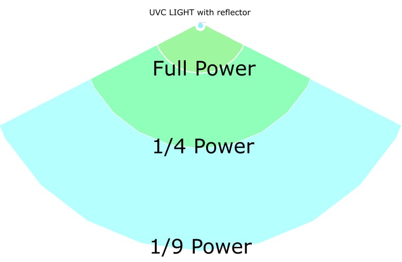
我们可以通过在移动机器人上添加UVC灯来解决这些问题,这样操作员就可以避免。当紫外线灯打开时,机器人将通过视觉和听觉警报通知用户。此外,如果机器人在UVC模式下检测到有人进入房间,安装在机器人上的运动传感器将关闭灯光。我们可以通过确保UVC灯靠近高接触区域来减少操作时间,从而增加UVC剂量。在每个UVC灯上添加一个机器人手臂将允许我们实现这一点。
1.1 Concept Photo Gallery
Physical Dimensions
Length = 29"Width = 22.5"Height = 72"Weight = 150 lbs ( 113lb calculated 37lb unaccounted margin)
3.Operating System
LIDIA will use Ubuntu 20.04.1 LTS Server Edition (Focal Fossa). Ubuntu is the recommended OS for the software platform and choosing the long-term support version allows for greater stability of the base system.
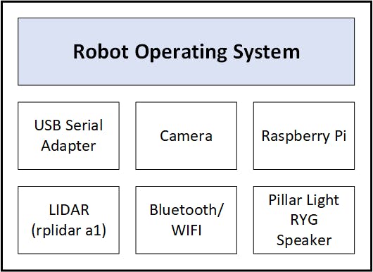
3.1ROS
The base framework to control the robot and cleansing operations will be Robot Operating System (ROS). It provides an extensive set of libraries to provide support for active and passive sensors, camera systems, and data recorders. Custom extensions can be written to manage add-ons as needed, for LIDIA this will be used to control the umbrella motion and activation.
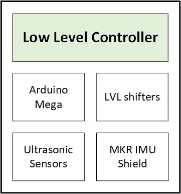
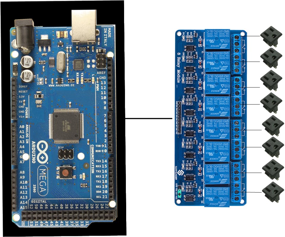
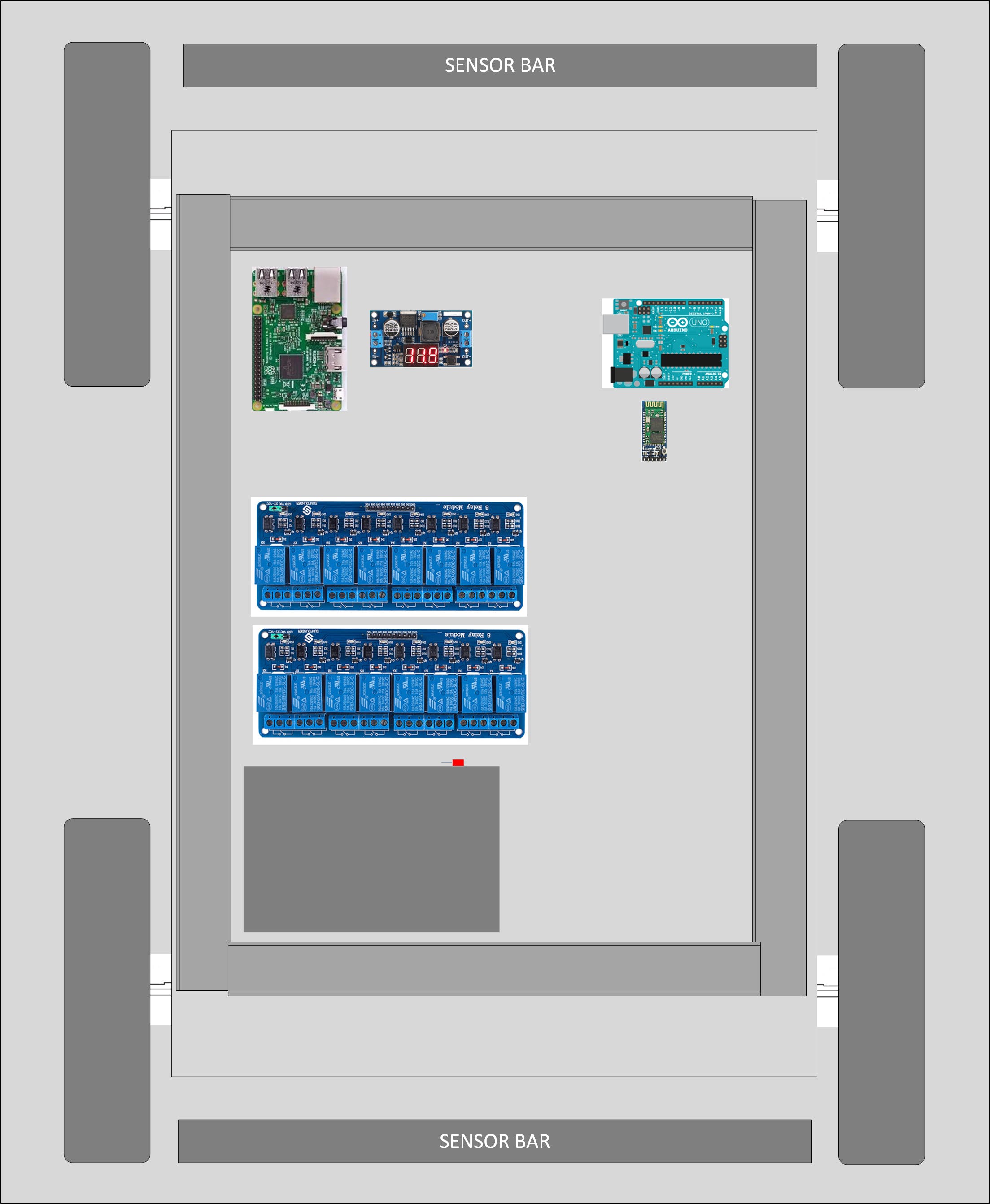
3.2 Microcontroller
The low level controller of the system will coordinate the movement and the sensors. It will control the drive using the X2 controller, arms, range sensors and exposure via relays.
The robot arms utilize simple linear actuators so a relay block can be used instead of a full motor controller.
4.Motion Platform
A commercially available robotic platform from Super Droid Robotics will be used. It provides a base that is approximately 18 by 15 inches and offers a high wheelbase of 6 inches providing a stable base for mounting of the UVC system. It is made from strong but lightweight aluminum and offers rigid mounting points for the light tower.
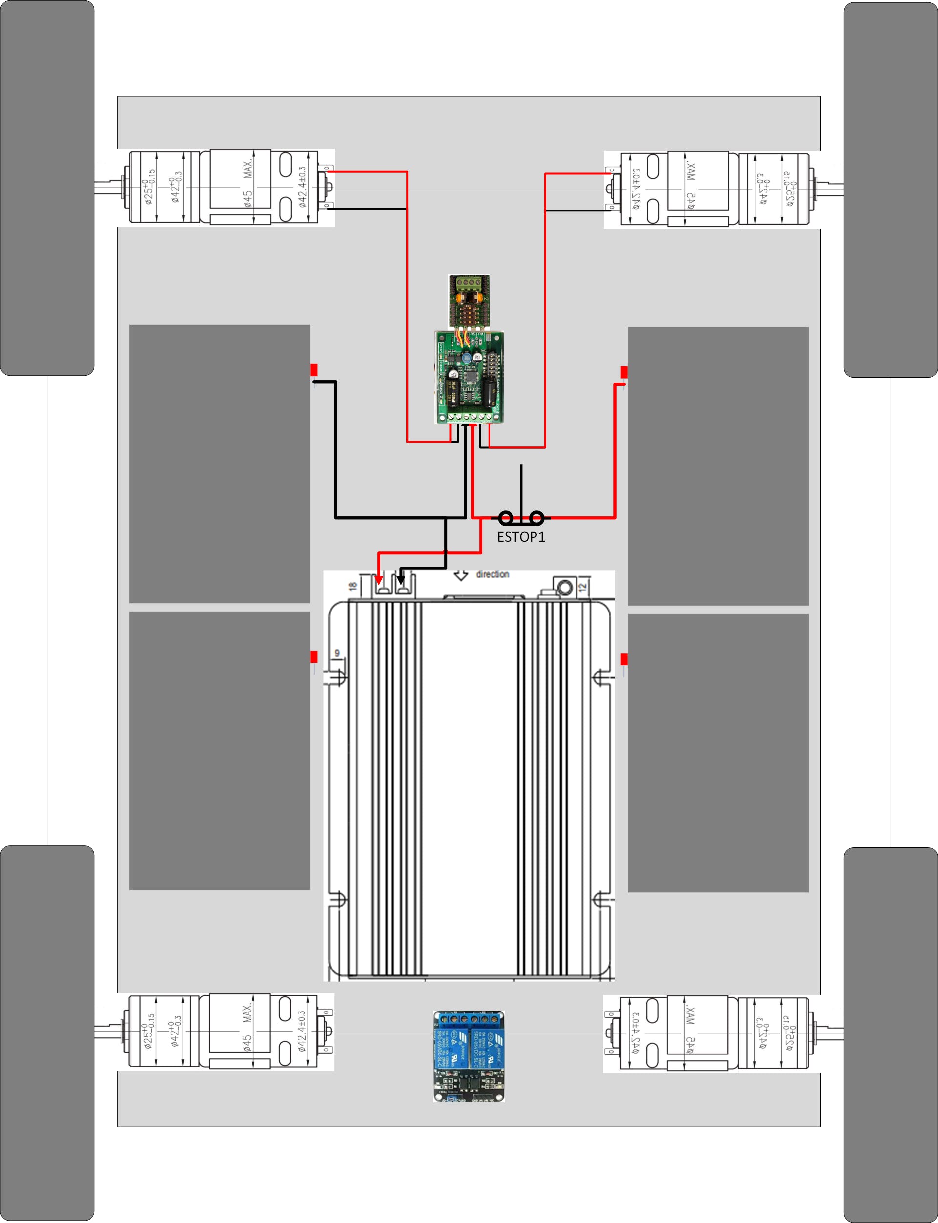
4.1Motors
Four brushed 24 VDC IG42 motors, geared to 122 RPM, will drive the robotic system with skid steering. These will each include a Quadrature Encoder wired for wheel shaft rotation monitoring. This information will be fed into the robot positioning algorithms.
4.2DriveFor this system a Sabertooth drive with a Kangaroo X2 PID controller was chosen. This solution has been available for over a decade and used in many robotics platforms. This allows easy positioning using serial commands to control the robot reducing the burden on the micro controller.
4.3Wheels
For the robot platform to be the most effective it should be practical and able to navigate commercial terrains such as carpet, tile, asphalt and concrete. The robot should also be able to handle the real world environment and navigate small inclines and bumps found in common floor transitions and curbs.
Mecanum wheels offer excellent control, however they are higher cost and offer no local repair options. Lower cost Mecanum wheels also perform poorly on concrete and asphalt.
Swerve drive or caster based swivel options also mar quickly on concrete and have a tendency to snag on small edges.
We found from our experience with robotics rubber pneumatic tires are the best real world solution. They come in multiple sizes and repair kits can be sourced in any bicycle or hardware store. The tires are typically reinforced and the inner tube is available at most hardware stores.
Below is a demo video from the fabricator of the super droid platform. Note the high base, ability to turn on its center axis and perform wide turns.
5.Power
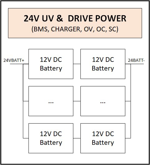
Power is provided to the robot using 12V SLA Batteries in series to provide 24V. The motion system and the inverter for the UVGI lamp are powered by the large 24V bank.
The main system for the OS and controllers are powered by an isolated 12V SLA and converted down to the lower logic voltages for sensors.
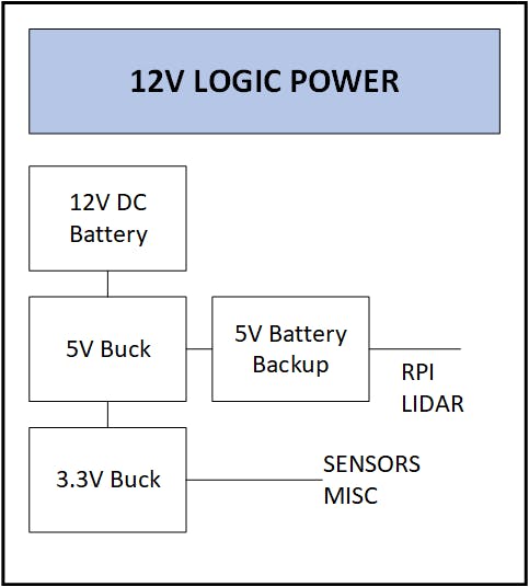
Two chargers are provided for both. A 24V battery charger with balancer is provided for the drive and disinfecting platform. A 12V battery charger is provided for the OS and electronics. The 12V system has a battery life of 8 hours. The 24V system can be supplemented with AC or operate for 30 min in a wireless mode.
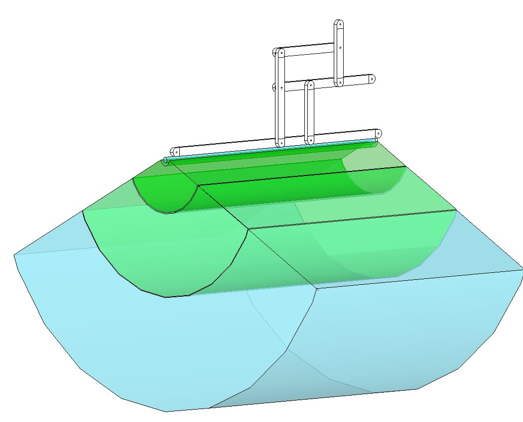
6.UVGI
The UV germicidal light source is chosen as a generic COTs component precertified for disinfecting use.
The UVGI lamp's chassis is mounted to the robot’s removable aluminum extrusion rail. This allows the entire lamp housing to be removed from the robot to introduce a spare.

The UVGI lamp is plugged into an array of 120V outlets on the robot base. These outlets are controlled by the microcontroller via 120V AC relays.
The lamp hours are stored in nonvolatile memory in the microcontroller. The OS can then recall this as needed to report when the lamp is near its EOL.
The lamp can be powered by the 12V SLA or the outlet. The robot is powered by the 12V SLA or a AC DC supply. Neither the motors or the UVGI is powered at the same time to reduce the overall load
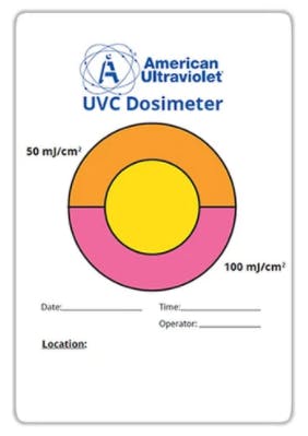
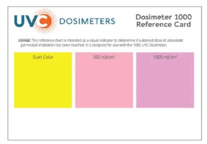
6.UVGIDosing Verification
Dosing and complex geometry is not practical for commerical applications. Also many times there can be confusion over the watts of the power in versus the optical energy. In order to reduce confusion a verified sensor would need to be included in each test. Most UVC sensors are in the $400-1000 range. In order to make it more tangible UVC dosimeters cards can be placed into each room to provide the customer positive confirmation each room was dosed properly.
7.Navigation
7.1 SLAM (Simultaneous Location and Mapping)
To provide a map for the robot we will request a floor plan from the commercial space in the quoting process. The operator will use a cell phone and this floor print to generate a path to be loaded into the robot using the web interface. This profile could be saved and a job worksheet will include a QR code to be scanned in order to recall the saved profile as the site planner may not be the operator.
7.2 Sensors
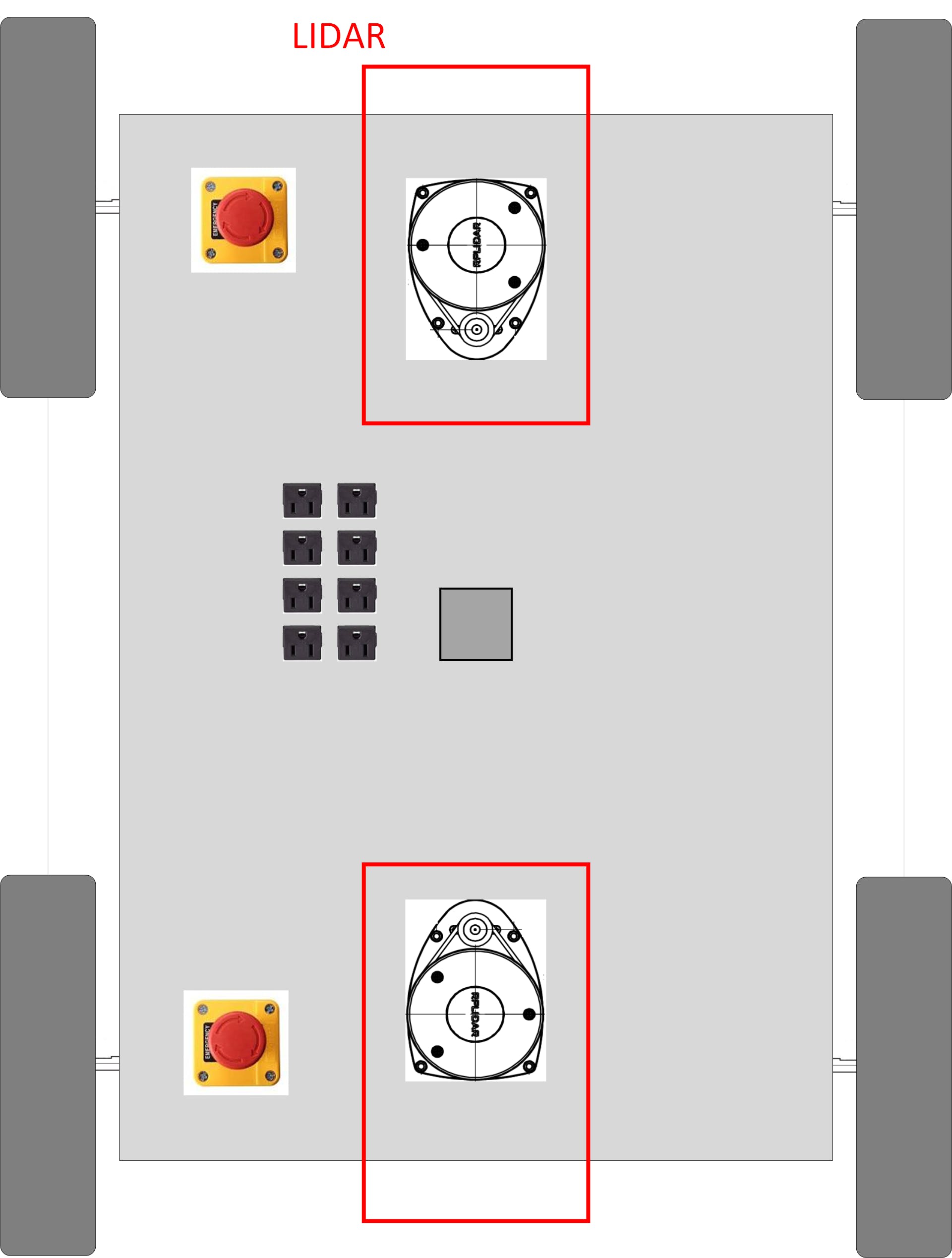
7.2.1 LIDAR
Two LIDAR systems are mounted on the third third of the chassis to provide mapping functionality. With more time and rotation of the robot the system can be optimized to only use 1 LIDAR to save costs. These connect over USB to the Raspberry Pi.
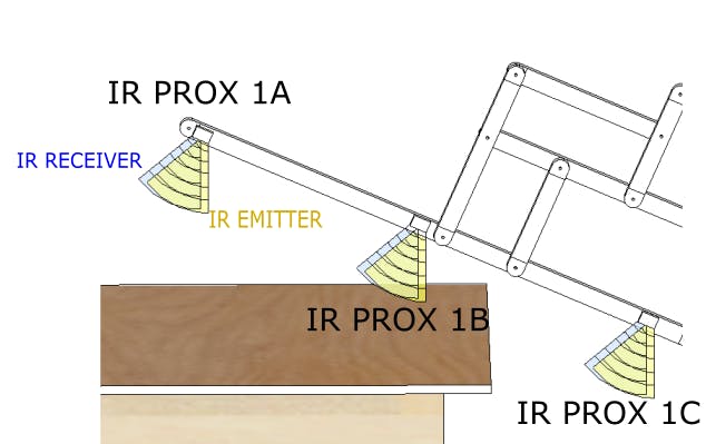
7.2.2 IRRange Finder
IR distance sensors will be mounted on the articulated UVC ARM allowing the arm to conform to the room without causing collisions. These will be used when the UVC light is not active and protect the light tubes from being damaged. There will be three IR distance sensors on each arm, totaling 24 total on the robot.
7.2.3 Ultrasonic Ground Sensor
These sensors will allow us to detect if the robot has tipped or if it is near a ledge like a stair case.
7.2.4 Inertial Nav System
A gyro, magnetometer, and accelerometer will form a navigation system for dead reckoning if needed. Dead reckoning is the process of calculating one's current position by using a previously determined position, or fix, by using estimations of speed and course over elapsed time. [wikipedia] In addition the system will aid in making precision turns.
8. Connectivity
8.1. Wifi
This is used to load configs, paths, watch the robot, etc. The Raspberry Pi contains a built in 802.11ac Wi-Fi adapter for control and reporting.
8.2 Bluetooth
The Raspberry Pi also has an internal Bluetooth 5.0 adapter that is co-located with the Wi-Fi. This will be used to initiate the Wi-Fi and provide the ability to alternatively control or debug operations.
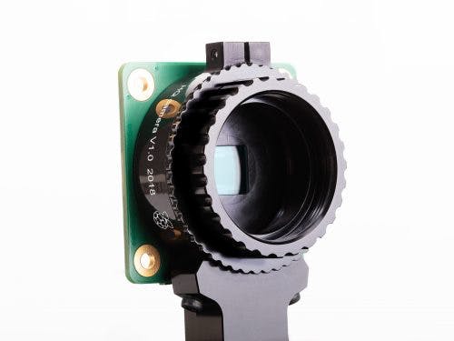
9. Vision
A Raspberry Pi High Quality Camera will be integrated into the system to integrate into collision detection using OpenCV. It will also be used to read QR Codes for tasking and control of the robot.
This system can also offer a RTSP video stream to monitor or navigate the robot remotely.
9.1 QR Code

QR Codes are used to quickly identify rooms or sections about to be cleansed. This offers an absolute verification system for the robot.
10. Mobile Application
The mobile application will be provided to load tasks and basic paths to follow. Bulb life, dosage times, and other data reporting will be displayed to the operator.
11. Logistics
LIDIA is designed to be transported easily using commercial vans so one or many can be deployed at an office.
All commercial offices will have floor plans. These will be scanned for the initial quote and adjusted with a site visit.
A user with a mobile phone can also create a path for the cleaning robots to traverse. The LIDIA robots will automatically follow the rough path and avoid obstacles and deploy conformal cleaning arms to match the contour of the room for the highest UV dose and fastest overall cleaning.
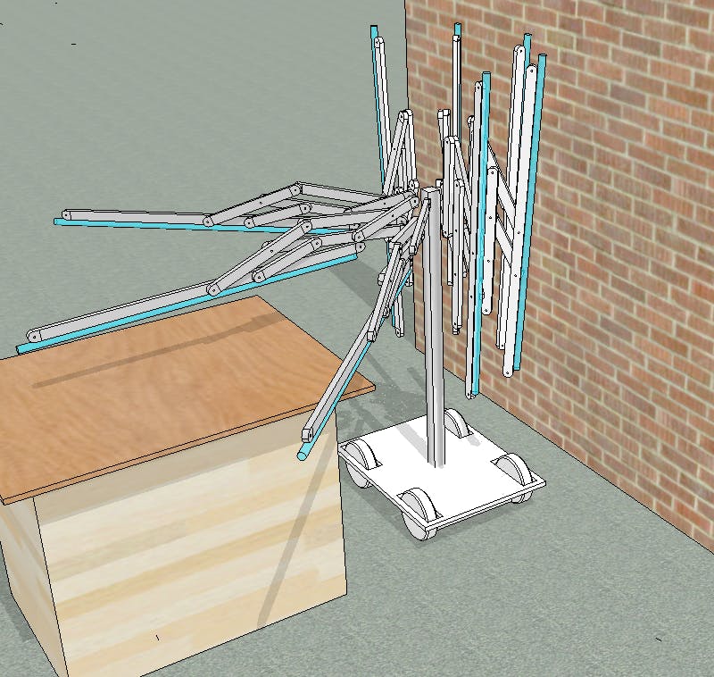
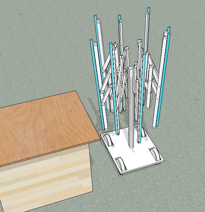
The robot will transition between umbrella mode and travel mode between each cleaning waypoint. Using the IMU, encoders, LIDAR to achieve SLAM the robot will navigate the preplanned route. Using computer vision and proximity sensors LIDIA will identify high touch areas and apply concentrated cleaning.
The initial test run will navigate the office to ensure the robot can traverse the path and to identify the AC outlets where available.
Special attention will be applied to high touch areas such as desks, chairs and doorways.
The human operator will ensure that the path of the robot is clear of obstructions and that the entryway doors are propped in the optimal position.
LIDIA will be equipped with tower lights and audio feedback to notify the operator and anyone in the facility of the cleaning. Also, the smart phone application will display the position of the robots.
In order to conserve battery life, the LIDIA robots will offer the option to power the UV lights and motor mechanism off internal 24VDC batteries or external 120VAC. Using the 120VAC is optimal, but not always available in all rooms or sites.
12. Safety
12.1Lamp Safety
The software will employ certain rules to avoid collisions.
1) The lamps will not be on when the robot is in motion, this will prevent accidental exposure
2) The robot will only move when the arms are in the upright position
12.2Collision Detection
The micro controller will perform the basic collision detection via IR sensors mounting on the front of the robot. This will ensure that the robot does not collide with people. Also as a general safety the robots speed can be controlled accurately using the Kangaroo X2 controller to ensure the speed is limited during cleaning.
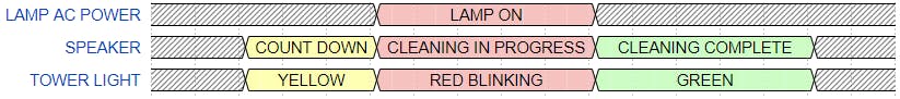
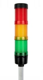
12.3Eye Safety is important as with UV light you do not have a natural blink response. We must ensure that the maintainers are properly protected and so an industry standard Andon tower light will indicate when the UV light will enable. When the robot is irradiating there will be a speaker announcement counting down when UV will be turned on and a notification while UV light is disinfecting. This will allow the platform to comply to Americans with Disabilities Act (ADA) requirements of offices, schools and transportation use.
The UV timer is limited to a max continuous dose via a hardware timer in the micro controller. If the max continuous dose is reached (30min) it will require human interaction to extend the dose timer.
PIR motion sensors are mounted on the top of the robot pillar and allow the robot to sense if any motion is occurring while it is dosing the room. If there is the robot can stop the cleaning process.
12.4 Emergency Stop
The safety switches will be located at the front and rear of the robot. These button sever power for the motors and the UVC system at the battery source.
Since the embedded system is on its own power source the fault can be reported via the smart phone utility that some interference has occurred.
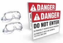
12.5 Safety Equipment
In order to properly work with UV the maintainer will need to have proper personal protective equipment.
Proper certified eyewear, gloves and skin protectors are needed.
Cotton gloves are needed in order to properly handle the UVC lamps. Fingerprints that could diminish the light output.
Proper ventilation is also a must even for ozone free lights
source [link]
13. COST
The overall cost of the robot is estimated at $6661.83 without accounting for assembly labor. The BOM attachment describes the key costs along with some estimated costs for items that were not quoted.
- COVID-19:手部消毒机 0次下载
- 消毒机器人Hanth-x1开源分享 0次下载
- 使用UVC和垃圾场材料的自主消毒机器人 0次下载
- UV-C消毒机器人开源分享 1次下载
- 全自动UV-C消毒机器人开源分享 1次下载
- 紫外线消毒机器人 2次下载
- 消毒机器人开源项目 2次下载
- Roboboi智能紫外线消毒机器人 1次下载
- Amabie消毒机器人开源分享 2次下载
- 自主UVC消毒机器人开源 2次下载
- 紫外线灯消毒机器人开源分享 2次下载
- 自动地板消毒机器人 0次下载
- 自动消毒与消毒警报开源 0次下载
- 瞳步消毒机器人方案
- 为什么空气消毒机选用LCD段码液晶屏 9次下载
- 基于51单片机的酒精消毒系统设计 392次阅读
- 基于STM32单片机的紫外线消毒系统设计 518次阅读
- 低功耗霍尔元件AH462在消毒柜中的应用 261次阅读
- 前沿开源技术领域的开源大数据一一解读 787次阅读
- 如何利用红外温度传感器设计一个口罩消毒装置 1789次阅读
- 如何使用LED进行消毒杀菌 4197次阅读
- 面对疫情 医疗机器人能帮上什么忙? 2022次阅读
- LED在消毒柜中的应用 1345次阅读
- 开源过程中的5件注意事项 3384次阅读
- 消毒柜的作用及常发生的故障原因及解决方法 5524次阅读
- 消毒柜的消毒方式及消毒原理分析 7198次阅读
- 紫外线传感器在餐具消毒机中的应用 681次阅读
- 紫外线传感器杀菌消毒原理解析 3570次阅读
- NASA的开源软件是什么?NASA的开源软件的详细分析 6904次阅读
- 可见光照明连续消毒是什么? 4270次阅读

 上传资料赚积分
下载排行
本周
- 1山景DSP芯片AP8248A2数据手册
- 1.06 MB | 532次下载 | 免费
- 2RK3399完整板原理图(支持平板,盒子VR)
- 3.28 MB | 339次下载 | 免费
- 3TC358743XBG评估板参考手册
- 1.36 MB | 330次下载 | 免费
- 4DFM软件使用教程
- 0.84 MB | 295次下载 | 免费
- 5元宇宙深度解析—未来的未来-风口还是泡沫
- 6.40 MB | 227次下载 | 免费
- 6迪文DGUS开发指南
- 31.67 MB | 194次下载 | 免费
- 7元宇宙底层硬件系列报告
- 13.42 MB | 182次下载 | 免费
- 8FP5207XR-G1中文应用手册
- 1.09 MB | 178次下载 | 免费
本月
- 1OrCAD10.5下载OrCAD10.5中文版软件
- 0.00 MB | 234315次下载 | 免费
- 2555集成电路应用800例(新编版)
- 0.00 MB | 33566次下载 | 免费
- 3接口电路图大全
- 未知 | 30323次下载 | 免费
- 4开关电源设计实例指南
- 未知 | 21549次下载 | 免费
- 5电气工程师手册免费下载(新编第二版pdf电子书)
- 0.00 MB | 15349次下载 | 免费
- 6数字电路基础pdf(下载)
- 未知 | 13750次下载 | 免费
- 7电子制作实例集锦 下载
- 未知 | 8113次下载 | 免费
- 8《LED驱动电路设计》 温德尔著
- 0.00 MB | 6656次下载 | 免费
总榜
- 1matlab软件下载入口
- 未知 | 935054次下载 | 免费
- 2protel99se软件下载(可英文版转中文版)
- 78.1 MB | 537798次下载 | 免费
- 3MATLAB 7.1 下载 (含软件介绍)
- 未知 | 420027次下载 | 免费
- 4OrCAD10.5下载OrCAD10.5中文版软件
- 0.00 MB | 234315次下载 | 免费
- 5Altium DXP2002下载入口
- 未知 | 233046次下载 | 免费
- 6电路仿真软件multisim 10.0免费下载
- 340992 | 191187次下载 | 免费
- 7十天学会AVR单片机与C语言视频教程 下载
- 158M | 183279次下载 | 免费
- 8proe5.0野火版下载(中文版免费下载)
- 未知 | 138040次下载 | 免费


 工商网监
工商网监
评论