随着可编程逻辑器件的发展,FPGA的应用已经越来越广泛,且用可编程逻辑器件代替传统的普通集成电路已成为一种发展的趋势。可编程逻辑器件FPGA以其高集成度、高速度、开发周期短、稳定性好而受到了人们
2021-01-04 10:36:00 2066
2066 
本章小结第8章 Xilinx可编程逻辑器件设计技巧8.1 概述8.2 可编程逻辑器件的时钟设计8.3 同步设计与提高器件工作速度8.4 存储器设计8.5 可编程逻辑器件FPGA的配置8.6
2012-02-27 14:43:30
可编程逻辑器件到底是干什么用的呢,简单的说,就是通过重新写程序,重新注入到这个器件中达到实现其它的功能。最常见的当属电脑了。电脑本身除了加法,减法和简单的逻辑运算四种。比如要是想实现一个功能让电脑
2014-04-15 10:02:54
可编程逻辑器件FPGA/CPLD结构与应用.ppt
2017-01-21 20:34:49
可编程逻辑器件(prog ramm able logic device,PLD)件的功能不是固定不变的,它可根据用户的需要而进行改变,即由编程的方法来确定器件的逻辑功能。可编程逻辑器件自 20 世纪
2019-02-26 10:08:08
芯片上,就可以得到一块专用集成电路。1.1 可编程逻辑器件可编程逻辑器件PLD(Programmable Logic Device)就是一种可以由用户定义和设置逻辑功能的数字集成电路,属于可编程
2021-07-13 08:00:00
可编程逻辑器件实验指导书
2009-09-16 15:11:22
可编程逻辑器件是如何发展的?
2021-04-29 06:23:22
应用,这种快乐试试你就会懂的。话不多说,上货。半导体存储器和可编程逻辑器件简介半导体存储器是一种能存储大量二值信息的半导体器件。在电子计算机以及其他一些数字系统的工作过程中,都需要对大量的数据进行存储
2023-02-23 15:24:55
PLD比学习单片机要简单的多,有数字电路基础,会使用计算机,就可以进行PLD的开发。不熟悉PLD的朋友,可以先看一看可编程逻辑器件的发展历程。开发PLD需要了解两个部分:1.PLD开发软件 2.PLD
2009-06-20 10:38:05
PLD可编程逻辑器件 英文全称为:programmable logic device 即 PLD。PLD是做为一种通用集成电路产生的,他的逻辑功能按照用户对器件编程来确定。一般的PLD的集成度很高
2021-07-22 09:05:48
` 本帖最后由 eehome 于 2013-1-5 09:47 编辑
XILINX可编程逻辑器件设计技术详解第1章 可编程逻辑器件设计流程导论11.1 设计流程概述11.2 设计输入和综合
2012-04-24 09:18:46
专家都是如何使用超低功耗的复杂可编程逻辑器件(CPLD)的?从他们的嵌入式设计中的I/O子系统中学到了什么?
2021-04-08 06:31:20
为什么复杂可编程逻辑器件需要重新上电才能工作?如何去解决AVR单片机上电复位不可靠的问题?
2021-07-07 06:53:08
- 固定逻辑器件和可编程逻辑器件。一如其名,固定逻辑器件中的电路是永久性的,它们完成一种或一组功能 -- 一旦制造完成,就无法改变。另一方面,可编程逻辑器件(PLD)是能够为客户提供范围广泛的多种逻辑容量
2009-05-29 11:36:21
分享一款不错的基于可编程逻辑器件PLD的数字电路设计方案
2021-04-30 06:34:54
摘要:介绍了可编程逻辑器件在数字信号处理系统中的应用。并运用VHDL语言对采用Lattice公司的ispLSI1032E可编程逻辑器件所构成的乘法器的结构、原理及各位加法器的VHDL作了详细的描述
2019-06-28 06:14:11
CLC5958的内部结构及基本特性CLC5958应用的注意事项有哪些采用可编程逻辑器件和A/D转换器组成的高速数据采集卡的设计方案
2021-04-15 06:50:05
怎么实现基于可编程逻辑器件的数字电路设计?
2021-05-06 08:36:18
本文以乘法器的设计为例,来说明采用可编程逻辑器件设计数字系统的方法。
2021-04-29 06:22:10
数字电子技术-- 可编程逻辑器件[hide][/hide]
2017-03-05 10:51:17
数字电子技术--可编程逻辑器件[hide][/hide]
2017-05-01 22:29:19
本文提出一种利用复杂可编程逻辑器件(Complex Programmable Logic Device,CPLD)设计技术[3]实现专用键盘接口芯片的方案。
2021-04-15 06:55:36
清华的可编程逻辑器件实验讲义cpld-2004-8-6-4
2012-08-16 17:06:20
随着智能制造的蓬勃发展进一步推动了智能工业的崛起。制造商及工程师在进行智能化系统设计时,将面临着不断提高性能、突出优势、降低成本、同时实现功能安全等诸多挑战,但同时也给全球可编程逻辑器件厂商带来
2013-04-12 09:57:41
有些疑问和大家求证下。什么叫可编程寄存器?>>> 是不是那种通过IO操作可以修改寄存器的值。什么叫可编程逻辑器件?>>>是不是就是器件和某一RAM相关联,修改
2013-07-13 17:06:40
如何选择PLC可编程逻辑器件?
2021-04-27 06:39:03
可编程逻辑器件设计
(264页,nlc格式)
2006-03-25 16:41:01 66
66 熟悉常用逻辑器件的分类;了解常用可编程逻辑器件的内部结构;熟悉可编程逻辑器件的开发流程;掌握MAX+plusII软件。重点:基于MAX+plusII软件进行PLD设计的流程。难点:PLD的
2008-12-01 17:36:4519 XC6SLX100-3FGG484C FPGA现场可编程逻辑器件 XILINX 现场可编程门阵列
2022-08-04 11:37:16
介绍了Altera公司生产的可编程逻辑器件EPM7032的内部结构和性能特点,给出了采用自顶向下的层次化设计方法进行自动交通控制系统的设计方案,同时给出了选用EPM7032可编程逻辑器件和M
2009-04-23 16:22:1260 本文通过详细介绍PLD 器件在积分式A/D 转换器数字控制部分的设计,说明可编程逻辑器件(PLD)主要是复杂可编程逻辑器件(CPLD)在数字逻辑系统设计中良好的移植性及稳定性。
2009-08-29 10:17:4328 可编程逻辑器件(programmable logic device,简称PLD)是最大规模甚至超大规模集成电路技术的飞速发展与计算机辅助设计(CAD)、计算机辅助生产(CAM)和计算机辅助测试(CAT)相结合的一种产物
2009-09-01 08:59:530 一种基于可编程逻辑器件的等精度频率计的设计原理、硬件组成和软件实现关键词:可编程逻辑器等精度 频率 周期 脉宽 占空比
2009-09-07 16:05:3431 可编程逻辑器件应用设计技巧100问:1. 么是.scf?答:SCF文件是MAXPLUSII的仿真文件, 可以在MP2中新建.2. 用Altera_Cpld作了一个186(主CPU)控制sdram的控制接口, 发现问题:要使得s
2009-10-01 19:00:0041 介绍了PLD(可编程逻辑器件) 的技术特点,并针对当前DSP 系统中串并转换器选择调试困难的特点,提出利用PLD 开发DSP 系统中高速串行到高速并行的数据转换传输技术,以简化电路及
2009-12-04 11:49:0417 可编程逻辑器件资料:Cyclone Device Handbook, Volume 1Stratix III Device Handbook, Volume 1MAX II Device Handbook
2009-12-08 16:32:170 基于复杂可编程逻辑器件(CPLD)的120MHZ高速AD采集卡的设计:介绍了一种基于复杂可编程逻辑器件高速AD采集卡的设计方法,给出了这种采集卡的硬件原理电路和主要的软件设计思路,采用
2010-01-17 09:37:4639 可编程逻辑器件基础及应用实验指导书
《可编程逻辑器件基础及应用》是一门侧重掌握可编程逻辑器件的基本结构和原理的课程。重点是使学生掌握基于可编程
2010-03-24 14:22:4629 基于单片机的复杂可编程逻辑器件快速配置方法
基于SRAM(静态随机存储器)的可重配置PLD(可编程逻辑器件)的出现,为系统设计者动态改变运行电路
2009-03-28 16:47:17749 
第三十二讲 可编程逻辑器件及应用第10章 可编程逻辑器件及应用10.1 概述10.1.1 PLD器件的基本结构10.1.2 PLD器件的分类10.1.3 PLD器件的优点一、
2009-03-30 16:37:511333 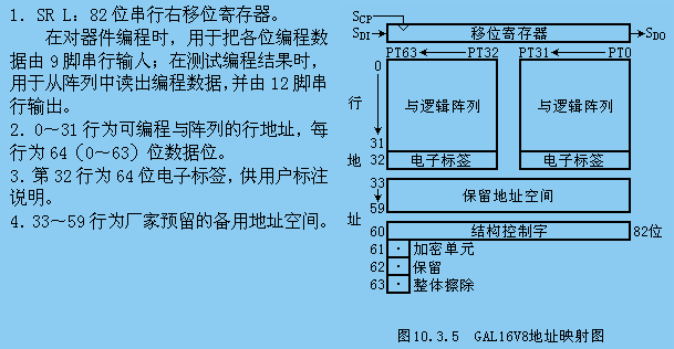
【摘 要】 介绍了可编程逻辑器件的结构、优点,及其在一种高准确度A/D转换器中的应用。设计中采用了通用阵列逻辑芯片GAL16V8。
2009-05-15 22:30:08781 
PLC可编程逻辑器件的选择方法
随着PLC的推广普及,PLC产品的种类和数量越来越多,而且功能也日趋完善。近年来,从美国、日本、德国
2009-06-19 13:11:05748 
什么是PLD(可编程逻辑器件)
PLD是可编程逻辑器件(Programable Logic Device)的简称,FPGA是现场可编程门阵列(Field Programable Gate Array)
2009-06-20 10:32:3214283 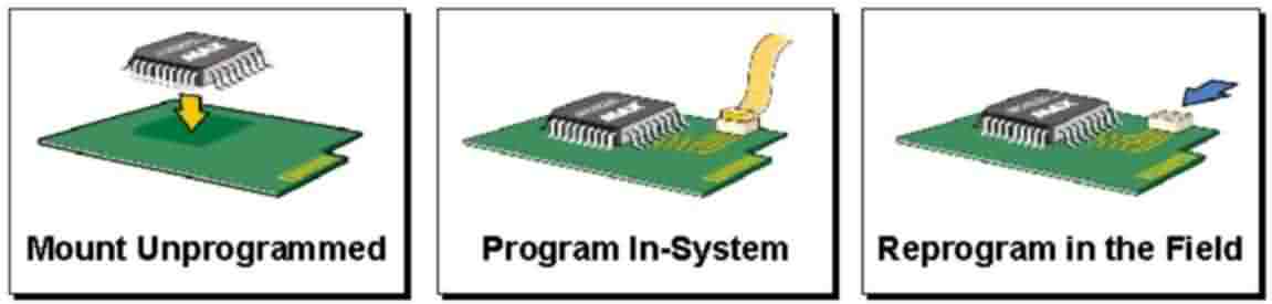
基于可编程逻辑器件的数字电路设计
0 引 言
可编程逻辑器件PLD(Programmable Logic De-vice)是一种数字电路,它可以由用户来进行编程和进行配置,利用它可以
2009-11-16 10:46:411473 
莱迪思半导体公司(NASDAQ: LSCC)今日宣布MachXO™ PLD(可编程逻辑器件)自量产起已经发运了超过7千5百万片。
2011-12-09 08:54:01663 7.1 可编程逻辑器件的基本原理 7.2 可编程逻辑器件的设计技术 7.3 可编程逻辑器件的编程与配置
2012-05-23 10:46:19142 可编程逻辑器件PLD(programmable logic device)是作为一种通用集成电路生产的,其逻辑功能按照用户对器件编程来决定。一般的PLD的集成度很高,足以满足设计一般的数字系统的需要
2012-06-16 22:13:38

Xilinx可编程逻辑器件的高级应用与设计技巧 作者:孙航;出版社:电子工业出版社 内容简介:介绍了Xilinx器件的结构和特性;以及ISE及其辅助设计工具,嵌入式处理器的原理与设计,
2012-11-28 14:18:01249 可编程逻辑器件简介,相关详细学习。
2016-04-26 16:55:360 可编程逻辑器件学习,压缩包内共10篇学文档
2016-09-02 16:54:4038 可编程逻辑器件FPGA/CPLD结构与应用
2016-12-11 23:38:390 数字电子技术--可编程逻辑器件
2016-12-12 22:07:220 数字电子技术-- 可编程逻辑器件
2016-12-12 22:07:220 由可编程逻辑器件与单片机构成的双控制器
2017-01-12 22:11:5611 基于单片机的复杂可编程逻辑器件快速配置方法
2017-01-18 20:35:098 双击【Xilinx Core Generator】,打开现有的IP核工程项目或者创建一个新的IP核工程。
2017-02-11 07:17:30626 
除了全局时钟缓冲器外,Spartan-6还包含驱动高速I/O时钟区域的时钟缓冲器。
2017-02-11 08:39:111198 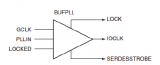
Spartan-6 LX平台面向逻辑、DSP资源以及存储模块进行了优化,能够以较低的功耗满足更高的带宽和性能需求;而Spartan-6 LXT面向逻辑、DSP以及存储资源进行优化,同时提供低功耗3.125Gbit/s串行收发器,可以实现PCI-e、SATA等高速串行接口。
2017-02-11 09:03:36509 
Spartan-6的每个SLICE 有8个存储元件,可以实现存储功能。
2017-02-11 09:56:141115 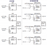
Spartan-6的时钟缓冲器/多路复用器(BUFG或BUFPLL)可以直接驱动时钟输入信号到时钟线上,或者通过多路复用器在两个不相关的信号甚至异步时钟信号中切换。
2017-02-11 09:59:11795 
可编程逻辑器件(书皮)
2022-07-10 14:34:540 可编程逻辑器件原理、开发与应用
2017-09-19 16:04:4919 对您的Xilinx逻辑器件进行编程。这将使得理论概念与硬件实现之间的关系从未变得如此简单。 Multisim环境中的可编程逻辑设备 在Multisim软件环境内,您可以使用可编程逻辑器件原理图中的专业可编程逻辑器件组件,以图形化的形式定义可编程逻辑器件(PLD)的内部结构。
2017-11-18 06:27:013235 根据PLD器件的与阵列和或阵列的编程情况及输出形式,可编程逻辑器件通常可分为4类。第一类是与阵 列固定、或阵列可编程的PLD器件,这类PLD器件以可编程只读存储器PROM为代表。可编程
2017-11-25 01:36:573653 在嵌入式系统里除了嵌入式处理器外还会经常使用到可编程逻辑器件,有些可编程逻辑器件在被焊接到印制电路板上之后还可以对其程序进行更新,这种特性称之为“在系统可重编程能力”(In SystemReprogrammability,ISR)。
2018-05-25 11:20:001458 
Peterson发起这个概念后,它们已经有很长的一段历史了。FPGA和它们最相近的兄弟复杂可编程逻辑器件(CPLD)的区别在于它们能够完成复杂功能的能力,它们就像一个“空白的画布”,它们的功能在之后被描绘在画布上,而不是由厂家预先特定地赋予。
2018-09-25 09:17:005847 关键词:PLD , 可编程逻辑 在数字电子系统领域,存在三种基本的器件类型:存储器、微处理器和逻辑器件。存储器用来存储随机信息,如数据表或数据库的内容。微处理器执行软件指令来完成范围广泛的任务
2019-02-23 14:42:011471 可编程逻辑器件即PLD。PLD是做为一种通用集成电路产生的,他的逻辑功能按照用户对器件编程来确定。一般的PLD的集成度很高,足以满足设计一般的数字系统的需要。
2019-12-11 07:03:002075 
FPGA可能确实很性感(以工程师的说法),但它们并不是唯一的可编程逻辑器件;其它设备也可以用单一设备提供一系列功能。看看来自Cypres半导体公司的“片上可编程系统”(PSoC)架构吧,它是工业上唯一一个在单片上结合了高性能模拟模块、可编程PLD、内存以及微控制器的可编程嵌入式SOC,并且功耗很低。
2019-08-28 08:35:503097 CPLD(复杂可编程逻辑器件),它是从PAL和GAL器件发展出来的器件,相对而言规模大,结构复杂,属于大规模集成电路范围。
2019-08-09 14:12:244769 
可编程逻辑器件(FPGA)一直以其设计灵活性以及现场可编程特性在市场上稳稳固守着一席之地,随着半导体制造工艺的进步,器件集成度越来越高,其应用也日益复杂。,
2019-11-21 14:51:27533 在嵌入式系统里除了嵌入式处理器外还会经常使用到可编程逻辑器件,有些可编程逻辑器件在被焊接到印制电路板上之后还可以对其程序进行更新,这种特性称之为“在系统可重编程能力。
2020-01-26 09:29:001294 
可编程逻辑器件(ProgrammableLogicDevice,PLD)是一种半定制集成电路,在其内部集成了大量的门和触发器等基本逻辑单元电路(LEs),用户通过编程来改变PLD内部电路的逻辑关系或连线,就可以得到所需要的设计电路。
2020-06-04 14:26:277380 可编程逻辑器件(PLD)是20世纪70年代发展起来的一种新型逻辑器件,是目前数字系统设计的主要硬件基础。根据可编程逻辑器件结构、集成度以及编程工艺的不同,它存在以下不同的分类方法。
2020-06-10 17:52:1926761 可编程逻辑器件PLD(Programmable Logic Device)就是一种可以由用户定义和设置逻辑功能的数字集成电路,属于可编程 ASIC。
2020-09-04 17:02:172383 可编程逻辑器件的设计方法经历了布尔等式,原理图输入,硬件描语言这样一个发展过程。随着设计的日益复杂和可编程逻辑器件规模的不断扩大,人们不停地寻求更加抽象的行为级设计方法,以便在尽可能短时间内完成自己的设计构思。
2020-09-11 18:41:001114 可编程逻辑器件(PLD--ProgrammableLogic Device):器件的功能不是固定不变的,而是可根据用户的需要而进行改变,即由编程的方法来确定器件的逻辑功能。
2021-01-21 17:04:0033 FPGA业界的可编程只读存储器(PROM)和可编程逻辑器件(PLD)萌芽。可编程只读存储器(PROM)和可编程逻辑器件(PLD)都可以分批在工厂或在现场(现场可编程)编程,然而,可编程逻辑被硬线连接在逻辑门之间。
2021-04-07 10:14:0276 可编程逻辑器件PLD课件下载
2021-08-13 10:58:2231 FPGA CPLD可编程逻辑器件的在系统配置方法(深圳市村田电源技术有限公司)-FPGA CPLD可编程逻辑器件的在系统配置方法
2021-09-18 10:51:2013 在过去的十年中,可编程逻辑器件(PLD)市场不断增长,对PLD的需求不断增加。具有可编程特性且可编程的芯片称为PLD。PLD也称为现场可编程器件(FPD)。FPD用于实现数字逻辑,用户可以配置集成电路以实现不同的设计。这种集成电路的编程是通过使用EDA工具进行特殊编程来完成的。
2022-03-22 12:36:245304 电可编程逻辑器件(Electrically Programmable Logic Device,EPLD)是指采用电信号的可擦可编程逻辑器件。
2022-08-22 18:12:37935 常见的可编程逻辑器件分为FPGA、EPLD(CPLD)。下面简单介绍两类器件的结构和区别。
2023-03-24 14:18:28798 
可编程逻辑器件 (Programmable Loeie Device,PLD)是一种用户编程实现某种逻辑功能的逻辑器件,主要由可编程的与阵列、或阵列、门阵列等组成,可通过编程来实现一定的逻辑功能
2023-06-06 15:35:59659 
可编程逻辑器件 (Programmable Loeie Device,PLD)是一种用户编程实现某种逻辑功能的逻辑器件,主要由可编程的与阵列、或阵列、门阵列等组成,可通过编程来实现一定的逻辑功能。
2023-06-06 15:37:45405 
可编程逻辑阵列(Programmable Logic Array, PLA):PLA是最早的可编程逻辑器件之一,由与非门阵列和或门阵列组成,通过编程配置来实现特定的逻辑功能。
2023-07-04 15:28:221360 可编程逻辑器件(Programmable Logic Device,PLD)是一类集成电路器件,可以根据用户的需求进行编程和配置,以实现特定的逻辑功能。它们具有可编程的逻辑门、时钟资源和互连结构,可以替代传统的固定功能逻辑芯片,提供更灵活和可定制的解决方案。
2023-09-14 15:25:551108 近日,AMD 宣布由于运行率和供应商可持续性的考量,将停产多款可编程逻辑器件产品(CPLD 和 FPGA),包括 XC9500XL、CoolRunner XPLA 3、CoolRunner II
2024-01-19 14:27:11229 近日AMD宣布,将停产多种可编程逻辑器件,包括 XC9500XL,CoolRunner XPLA 3、CoolRunner II、Spartan II 和 Spartan 3、3A、3AN、3E、3ADSP ,以及面向商业/工业的“XC”和面向汽车“XA”产品系列。
2024-01-24 17:37:21451 
可编程逻辑器件是一种集成电路,具有可编程功能的特性。它们可以根据用户的需求进行编程,从而实现不同的逻辑功能。
2024-02-26 18:24:03576
 电子发烧友App


 工商网监
工商网监
评论