 信号寻迹器/信号发生器(英文),Pulse-Generator & Signal-Tracer

信号寻迹器/信号发生器(英文),Pulse-Generator & Signal-Tracer
关键字:信号寻迹器/信号发生器
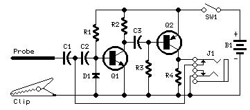
Circuit diagram
Parts:
R1 1M 1/4W Resistor
R2,R4 2K7 1/4W Resistors
R3 150K 1/4W Resistor
C1 2n2 630V Ceramic or Polyester Capacitor (See Notes)
C2,C3 4n7 63V Ceramic or Polyester Capacitors
D1 1N4148 75V 150mA Diode
Q1 BC547 45V 100mA NPN Transistor
Q2 BC557 45V 100mA PNP Transistor
SW1 SPST miniature Slider Switch (See Notes)
J1 Stereo switched 3mm. Jack socket (See Notes)
Probe Metal Probe 3 to 5 cm. long
Clip Miniature Crocodile Clip
B1 1.5V Battery (AA or AAA cell etc.)
Device purpose:
This simple circuit generates narrow pulses at about 700-800Hz frequency. The pulses, containing harmonics up to the MHz region, can be injected into audio or radio-frequency stages of amplifiers, receivers and the like for testing purposes. A high-pitched tone can be heard from the speaker of the device under test when all is working properly. The clip must be connected to the ground of the device under test, touching with the probe the different stages of the circuit, starting from the last stage and going up towards the first. When the tone is no longer heard, the defective stage has been found.
Connecting an earclip or headphone to J1, the circuit will automatically change into a two-stage amplifier and any audio signal coming from the device under test and picked-up by the probe will be heard through the headphones. The testing of a circuit should be made in the reverse manner, i.e. starting from the first stage and going down until the last stage. When nothing is heard, the defective stage has been found.
Circuit operation:
Q1 & Q2 form a complementary astable multivibrator, whose operating frequency is set mainly by R3, C2 & C3 values. Output pulses are taken at Q2 Collector and applied to the probe by means of decoupling capacitor C1. D1 provides a symmetrical shape for the output waveform.
If an earclip or headphone jack is plugged into J1, the connection from Q2 Collector and C1-C2 is broken by the switch incorporated into J1: in this case the circuit becomes a two-stage amplifier.
Notes:
If you intend to use the circuit to test valve operated devices C1 must be a 630V type. Working with low voltage supply transistor devices the voltage of C1 can be lowered to 63 or 100V.
If instead of a short probe, you intend to connect the circuit to the device under test by means of a piece of wire longer than a few centimeters, a small ceramic capacitor (470 to 1000pF) should be added in parallel to D1 to prevent unwanted RF oscillation.
Current drawing when in Pulse-Generator mode is about 60µA & 1.2mA when in Signal-Tracer mode operation. Therefore SW1 can be omitted, provided that the earclip or headphones are unplugged when the circuit is unused.
J1 is a stereo switched jack socket wired to obtain a series connection of the two earpieces forming a stereo headphone. In this manner the circuit is loaded with a higher impedance and sensitivity will be improved.
Therefore, the higher the load impedance the more sensitive the Signal-Tracer. In any case, common 32 Ohm impedance mini-headphones suitable for walkman sets will work fine.
A crystal (high impedance) earpiece is a good solution, provided you substitute J1 with a mono switched jack socket.
The entire circuit can be easily fitted into a pen-like enclosure, with the probe protruding like a nib.
Author: RED Free Circuit Designs
声明:本文内容及配图由入驻作者撰写或者入驻合作网站授权转载。文章观点仅代表作者本人,不代表电子发烧友网立场。文章及其配图仅供工程师学习之用,如有内容侵权或者其他违规问题,请联系本站处理。
举报投诉
发布评论请先 登录
相关推荐
热点推荐
锁相放大器与信号发生器的同步原理与实现方法
在精密物理测量、弱信号检测及科研实验中,锁相放大器(Lock-in Amplifier)与信号发生器(Signal Generator)是两

锁相放大器与信号发生器的同步方法
在精密测量与信号处理领域,锁相放大器(Lock-in Amplifier)与信号发生器(Signal Generator)的同步是实现高信噪
函数信号发生器和任意波形信号发生器区别详解
函数发生器提供了一个预置列表,里面列出了它可以生成的波形或码型。 在函数发生器中,用户可以更改频率、幅度和偏移等波形参数,还可添加简单的失真。 任意波形发生器更为复杂,能够仿真真实世界中的信号


信号发生器的构成和工作原理
信号发生器作为现代电子测试与测量领域中的关键设备,其精密的构造和巧妙的工作原理使之能够产生各种所需的电信号。本文将深入探讨信号发生器的构成及


评论