 构建一个带Arduino代码的颜色检测器电路

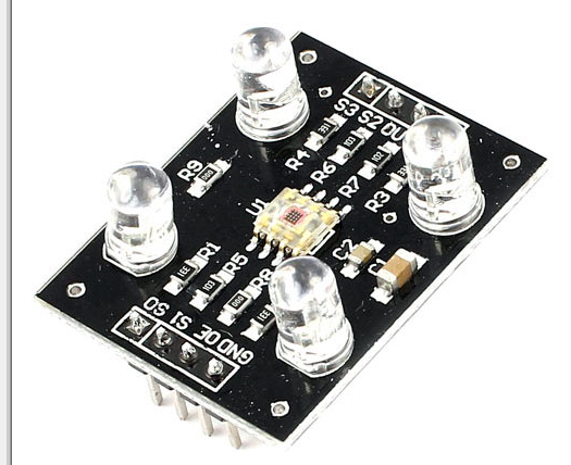
在这篇文章中,我们将构建一个可以检测颜色并触发相应分配继电器的电路。该项目是使用 TCS3200 颜色传感器和 Arduino 板完成的。
通过 TCS3200 进行颜色感应
如果您希望电路根据颜色采取行动,则建议的项目可能会很有用。在各种工业领域,基于颜色检测的应用海量很大。
该项目将深入了解我们如何对颜色传感器进行编程以检测不同的颜色并触发继电器。
我们将考虑该项目的原色:红色、绿色和蓝色。该项目可以区分这三种颜色并触发继电器,每个继电器代表每种颜色。
TCS3200 可以检测任意数量的颜色,但为了使项目易于理解并保持程序代码简单,我们只关注原色。
电路图:
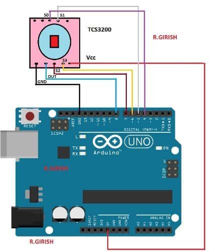
以上原理图用于连接Arduino和TCS3200颜色传感器。
继电器连接:
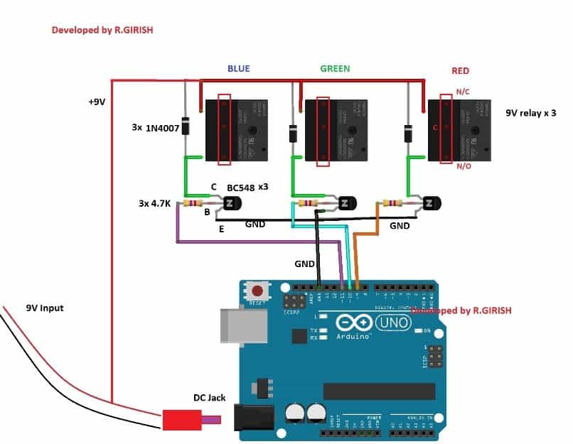
使用至少 9mA 的 500V 适配器为 Arduino
供电。晶体管充当继电器的放大器,因为Arduino的GPIO引脚不能提供足够的电流来继电器。
二极管 1N4007 将吸收继电器线圈的高压尖峰,保护其余半导体元件。
硬件到此结束。
现在让我们看看如何上传代码并根据您的要求校准传感器。
颜色灵敏度可能因模块而异,环境光会极大地改变颜色灵敏度。
所有TCS3200传感器在制造时都有一些变化,您必须测量当前拥有的传感器的颜色参数,以便可以在代码中使用这些参数来更准确地检测颜色。
要校准和优化传感器的读数,请精确执行以下步骤:
步骤 1:上传以下代码并完成硬件设置。
//--------Program Developed by R.GIRISH-------//
const int s0 = 4;
const int s1 = 5;
const int s2 = 6;
const int s3 = 7;
const int out = 8;
int frequency1 = 0;
int frequency2 = 0;
int frequency3 = 0;
int state = LOW;
int state1 = LOW;
int state2 = HIGH;
void setup()
{
Serial.begin(9600);
pinMode(s0, OUTPUT);
pinMode(s1, OUTPUT);
pinMode(s2, OUTPUT);
pinMode(s3, OUTPUT);
pinMode(out, INPUT);
//----Scaling Frequency 20%-----//
digitalWrite(s0, state2);
digitalWrite(s1, state1);
//-----------------------------//
}
void loop()
{
//-----Sensing RED colour-----//
digitalWrite(s2, state1);
digitalWrite(s3, state1);
frequency1 = pulseIn(out, state);
Serial.print(“RED = ”);
Serial.print(frequency1);
Serial.print(“ |”);
delay(100);
//------Sensing Green colour----//
digitalWrite(s2, state2);
digitalWrite(s3, state2);
frequency2 = pulseIn(out, state);
Serial.print(“ Green = ”);
Serial.print(frequency2);
Serial.print(“ |”);
delay(100);
//------Sensing Blue colour----//
digitalWrite(s2, state1);
digitalWrite(s3, state2);
frequency3 = pulseIn(out, state);
Serial.print(“ Blue = ”);
Serial.println(frequency3);
delay(100);
Serial.println(“-----------------------------”);
delay(400);
}
//---------Program Developed by R.GIRISH---------//
Step 2: Open the serial monitor, you will find the color parameters like
this:
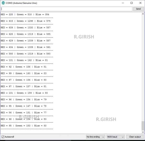
Bring the color object (colored paper is preferred) red, blue and
green.
Step 3:
• Place the red colored paper close to the TCS3200 sensor.
• Note down the R, G, B readings (all three colours) while you place the
red colour paper.
• Similarly note down the R, G, B reading for green and blue color
papers.
• NOTE: when you place any of the 3 colors in front of the TCS3200 note
down all the red, blue and green readings for each color paper, which you need
to enter in the main color detection program.
Step 4: Read Step 5 and upload the main below code (color detection
program)
//-----Program Developed by R.GIRISH-----//
const int Red_relay = 9;
const int Green_relay = 10;
const int Blue_relay = 11;
const int s0 = 4;
const int s1 = 5;
const int s2 = 6;
const int s3 = 7;
const int out = 8;
int var = 25;
int red = 0;
int green = 0;
int blue = 0;
int state = LOW;
int state1 = LOW;
int state2 = HIGH;
//-----------Enter Values--------//
//For RED Colour:
int Rx1 = 92;
int Gx1 = 240;
int Bx1 = 53;
//For GREEN Colour:
int Rx2 = 228;
int Gx2 = 163;
int Bx2 = 64;
//For BLUE Colour:
int Rx3 = 300;
int Gx3 = 144;
int Bx3 = 45;
//----------------------------//
void setup()
{
Serial.begin(9600);
pinMode(Red_relay, OUTPUT);
pinMode(Green_relay, OUTPUT);
pinMode(Blue_relay, OUTPUT);
digitalWrite(Red_relay, LOW);
digitalWrite(Green_relay, LOW);
digitalWrite(Blue_relay, LOW);
pinMode(s0, OUTPUT);
pinMode(s1, OUTPUT);
pinMode(s2, OUTPUT);
pinMode(s3, OUTPUT);
pinMode(out, INPUT);
//----Scaling Frequency 20%-----//
digitalWrite(s0, state2);
digitalWrite(s1, state1);
//-----------------------------//
}
void loop()
{
int redH1 = Rx1 + var;
int redL1 = Rx1 - var;
int redH2 = Rx2 + var;
int redL2 = Rx2 - var;
int redH3 = Rx3 + var;
int redL3 = Rx3 - var;
int blueH1 = Bx1 + var;
int blueL1 = Bx1 - var;
int blueH2 = Bx2 + var;
int blueL2 = Bx2 - var;
int blueH3 = Bx3 + var;
int blueL3 = Bx3 - var;
int greenH1 = Gx1 + var;
int greenL1 = Gx1 - var;
int greenH2 = Gx2 + var;
int greenL2 = Gx2 - var;
int greenH3 = Gx3 + var;
int greenL3 = Gx3 - var;
//-----Sensing RED colour-----//
digitalWrite(s2, state1);
digitalWrite(s3, state1);
red = pulseIn(out, state);
delay(100);
//------Sensing Green colour----//
digitalWrite(s2, state2);
digitalWrite(s3, state2);
green = pulseIn(out, state); ;
delay(100);
//------Sensing Blue colour----//
digitalWrite(s2, state1);
digitalWrite(s3, state2);
blue = pulseIn(out, state);
delay(400);
if(red 《= redH1 && red 》= redL1)
{
if(green 《= greenH1 && green 》= greenL1)
{
if(blue 《= blueH1 && blue 》= blueL1)
{
Serial.println(“Detected Colour: RED”);
Serial.println(“”);
digitalWrite(Red_relay, HIGH);
delay(1000);
}
}
}
if(red 《= redH2 && red 》= redL2)
{
if(green 《= greenH2 && green 》= greenL2)
{
if(blue 《= blueH2 && blue 》= blueL2)
{
Serial.println(“Detected Colour: Green”);
Serial.println(“”);
digitalWrite(Green_relay, HIGH);
delay(1000);
}
}
}
if(red 《= redH3 && red 》= redL3)
{
if(green 《= greenH3 && green 》= greenL3)
{
if(blue 《= blueH3 && blue 》= blueL3)
{
Serial.println(“Detected Colour: Blue”);
Serial.println(“”);
digitalWrite(Blue_relay, HIGH);
delay(1000);
}
}
}
}
//------Program Developed by R.GIRISH--------//
第 5 步: 在上面的代码中,将值替换为您最近记下的值:
//-- -- -- -- Enter Values-- -- --//
//For RED Colour:
int Rx1 = 92;
int Gx1 = 240;
int Bx1 = 53;
//For GREEN Colour:
int Rx2 = 228;
int Gx2 = 163;
int Bx2 = 64;
//For BLUE Colour:
int Rx3 = 300;
int Gx3 = 144;
int Bx3 = 45;
//-- -- -- -- -- -- -- -- -- -- -- //
当您将红色纸放在传感器上时,您将获得三个读数,例如R = 56 |G = 78 |B = 38。
按如下所示放置值 56、78、38:
对于红色:
int Rx1 = 56;
int Gx1 = 78;
int Bx1 = 38;
同样,对于其他两种颜色并上传代码。
步骤6:
• 打开串行监视器,将三种颜色中的任何一种放在传感器前面。
•您将在串行监视器上看到颜色检测;同时激活相应的颜色继电器。
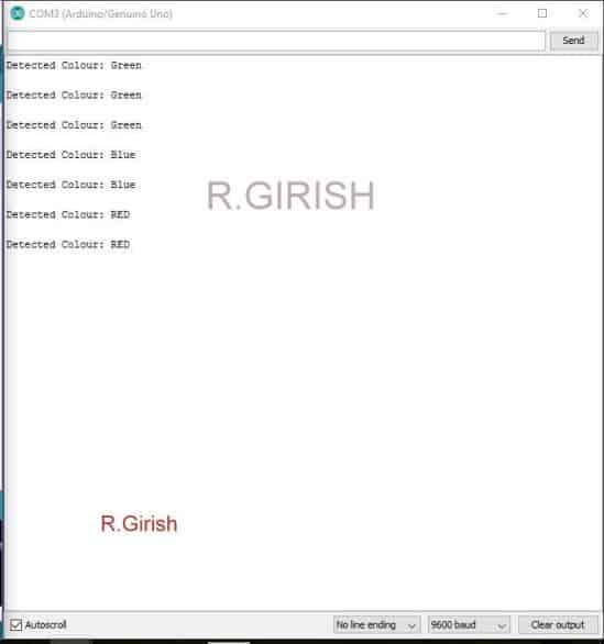
• 您有 Arduino 板上的重置按钮来停用继电器。
注1:校准后,如果您放置的红色,绿色,蓝色物体/纸张的阴影/色调略有不同,则电路可能无法检测到颜色。换句话说,您必须使用完全相同颜色的物体/纸张来检测颜色并触发中继。
注2:环境光会影响颜色检测,因此,在校准和检测颜色时,请在传感器附近保持一致的光线。
-
检测电路
+关注
关注
13文章
317浏览量
59804 -
检测器
+关注
关注
1文章
951浏览量
50225 -
Arduino
+关注
关注
191文章
6535浏览量
197807
发布评论请先 登录

采用Arduino开发板、火焰传感器和蜂鸣器构建火感检测器系统
使用二极管和电容器构建简单的峰值检测器电路
Arduino Light Clapper使用声音检测器

使用TCS230 TCS3200颜色传感器制作颜色检测器


评论