 新品开箱 | RL78/G15开发板 Step by Step点灯


前篇回顾
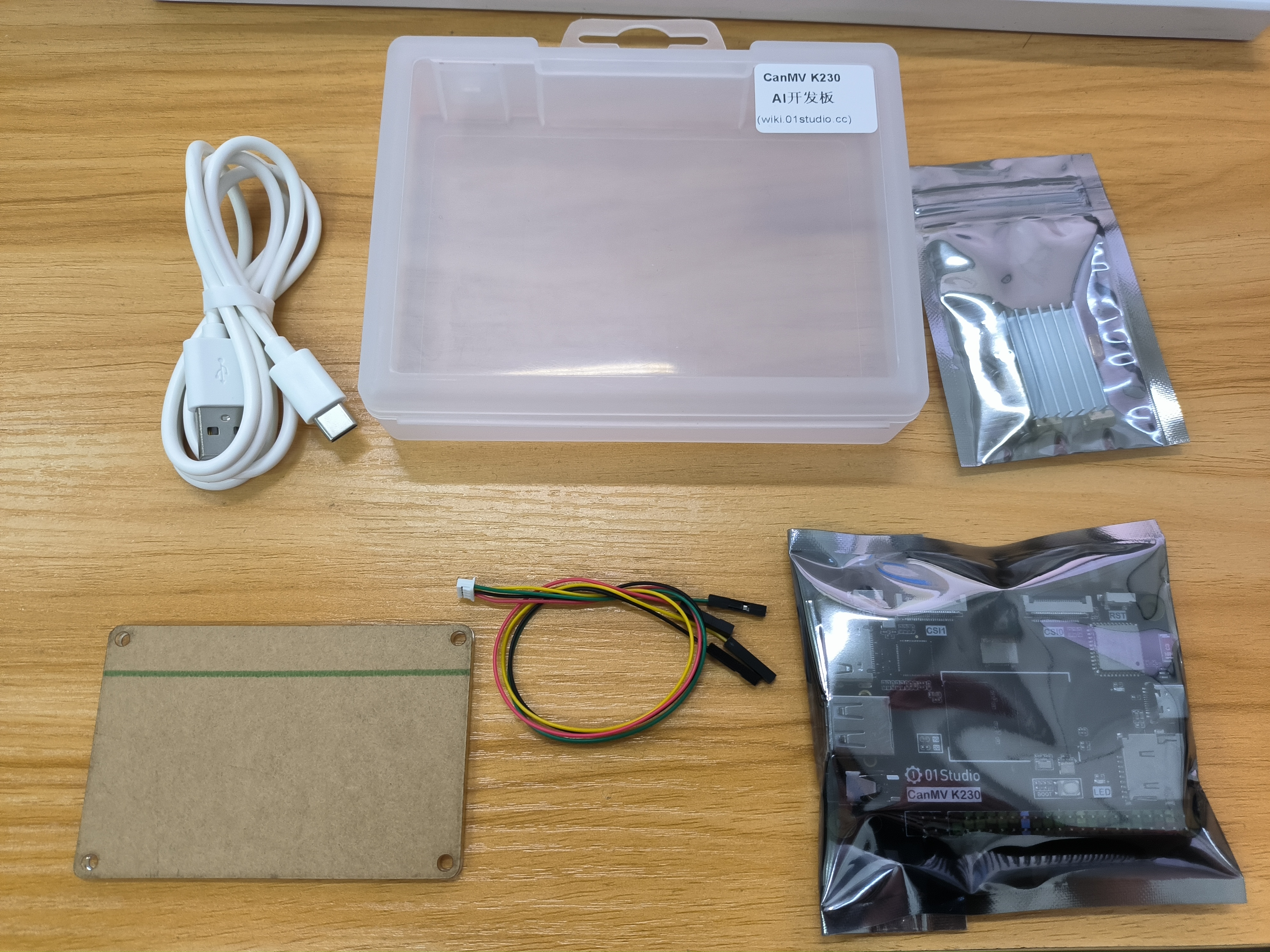
新品开箱 | RL78/G15开发板开箱与开发环境搭建
基于e2 studio点灯
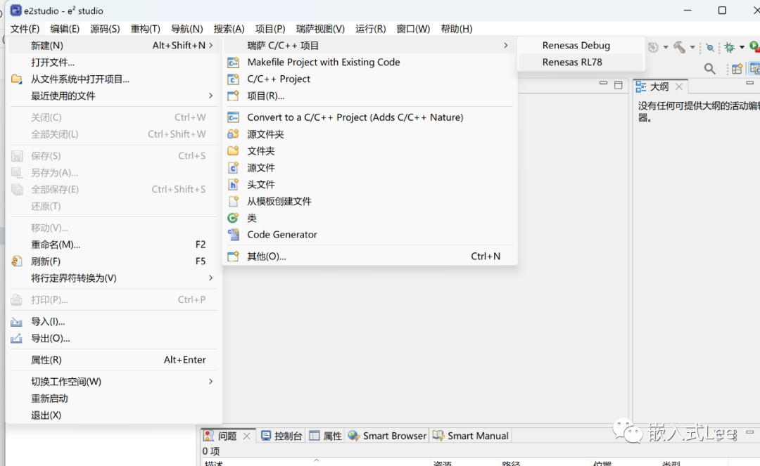
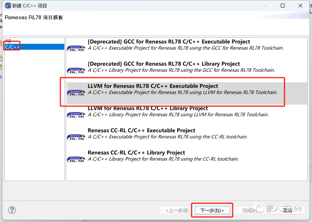
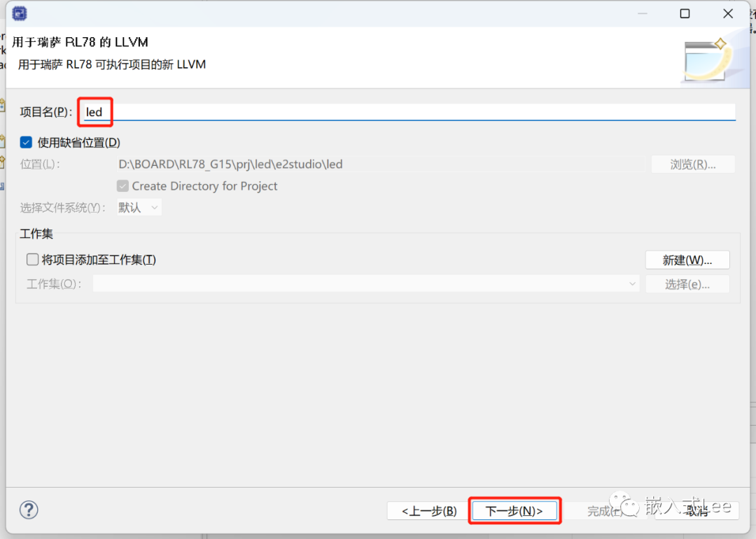
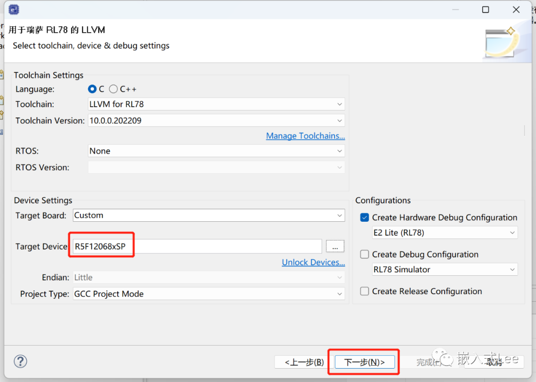
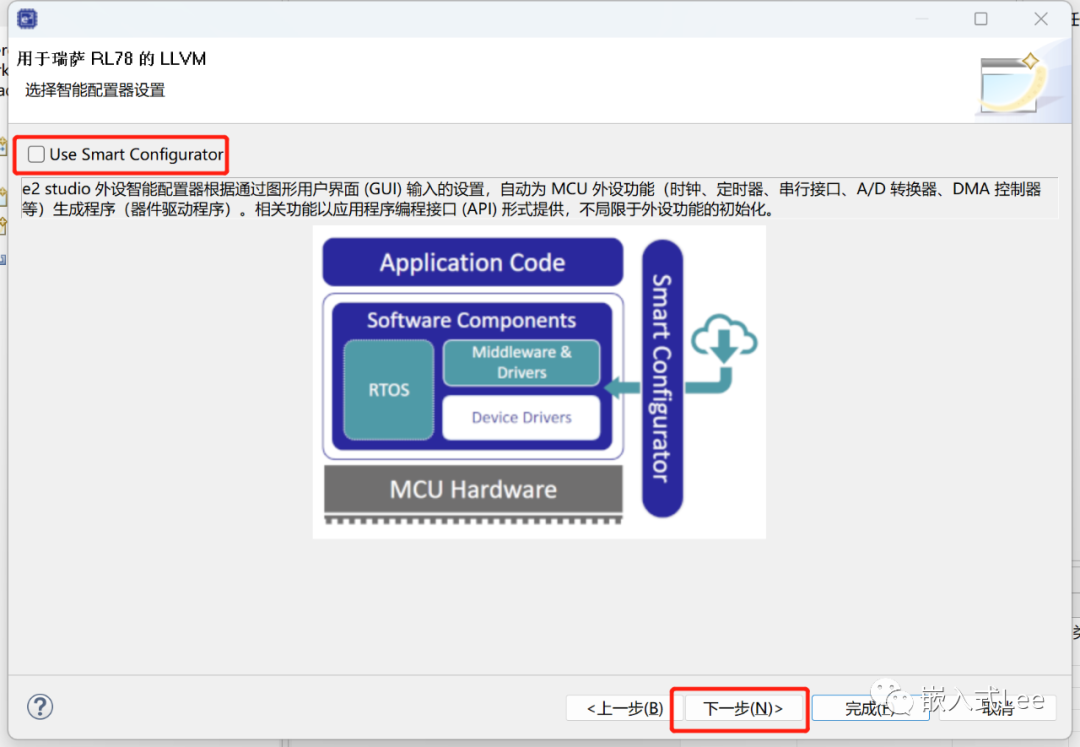
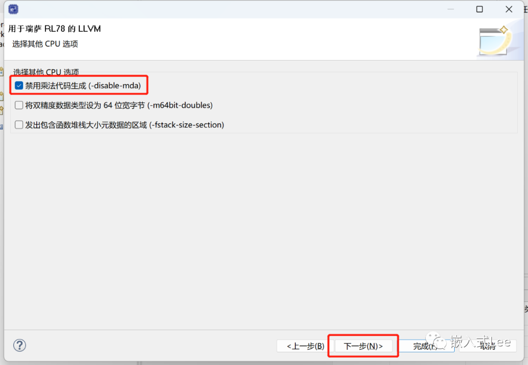
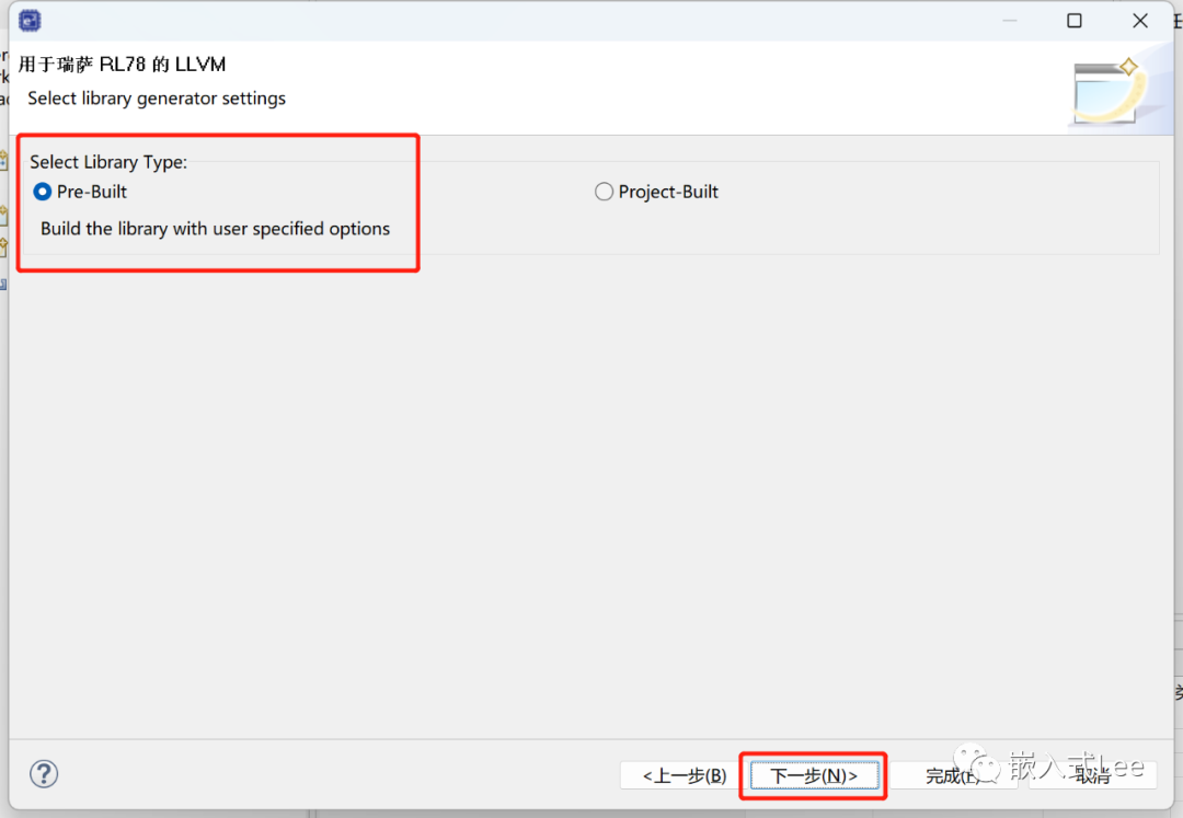
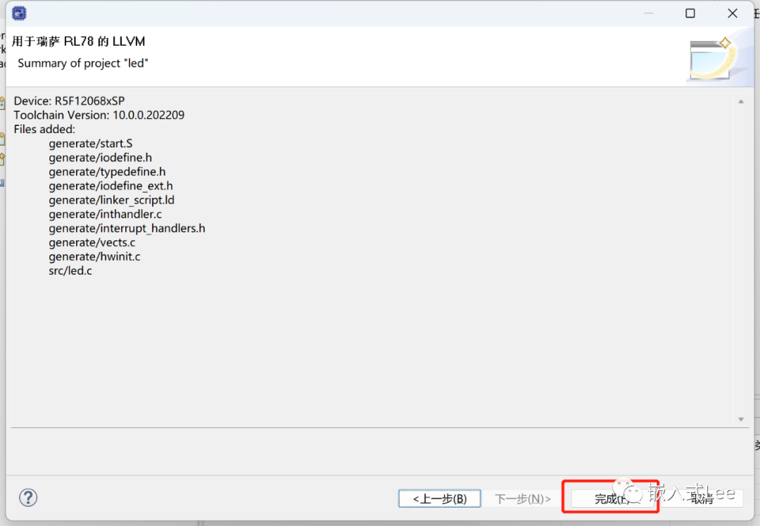
新建工程
文件->新建->瑞萨C/C++项目->Renesas RL78
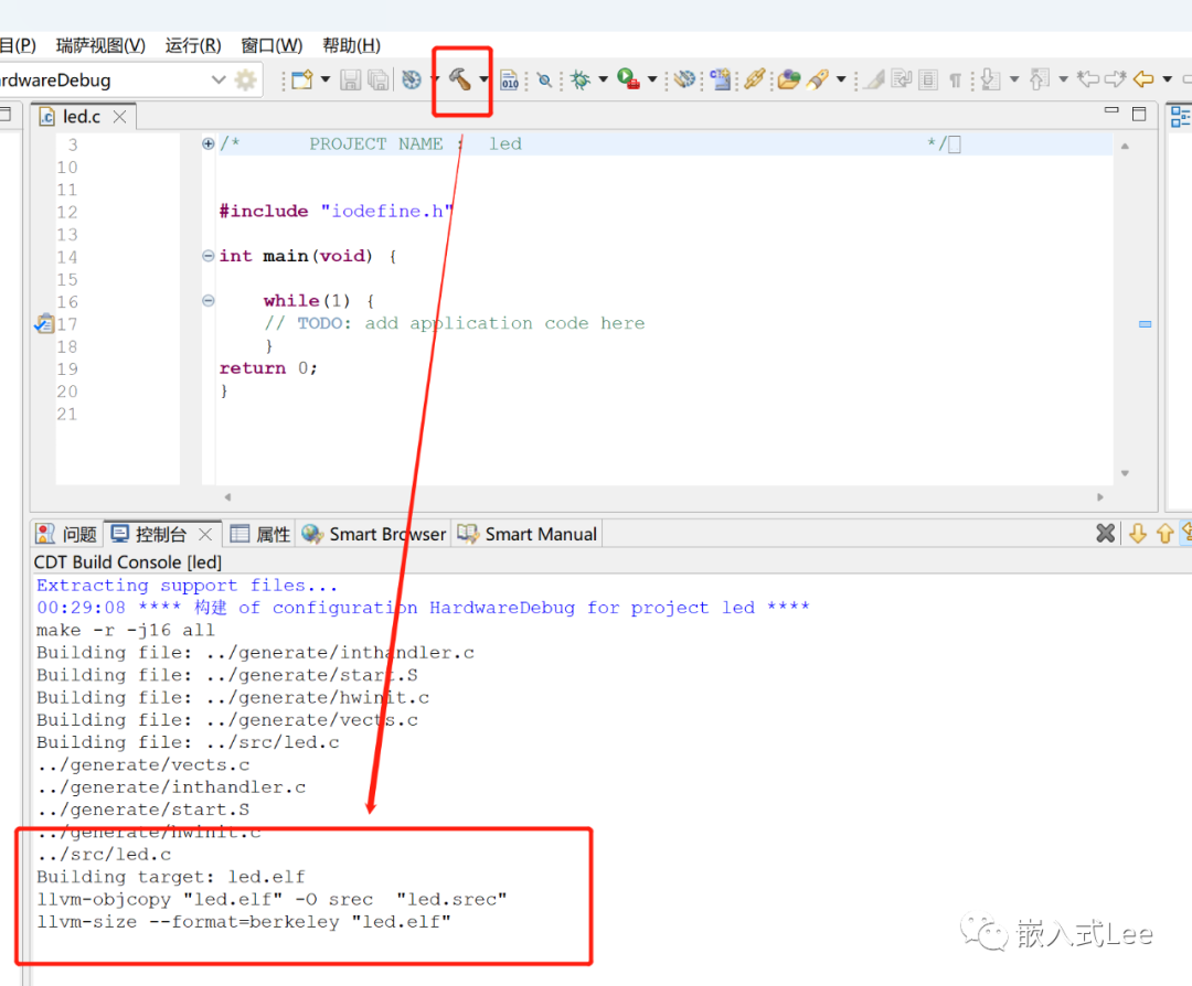
构建项目
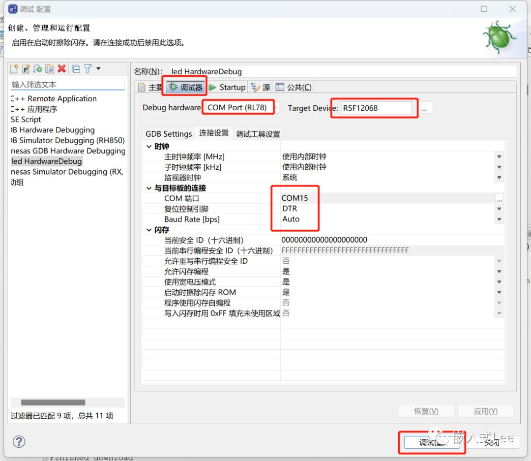
仿真配置
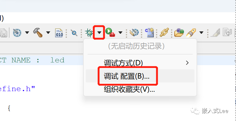
点开Renesas GDB Hardware Debug下的led Hardwaredebug
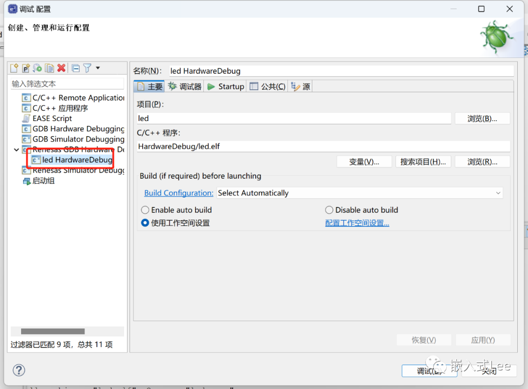
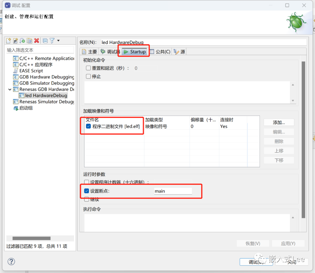
仿真器设置如下,点击调试
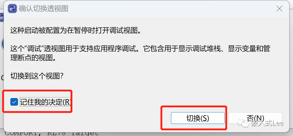
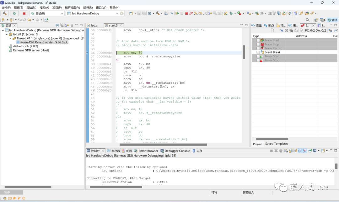
进入仿真环境如下
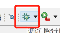
配置好后可以直接点击如下图标进入
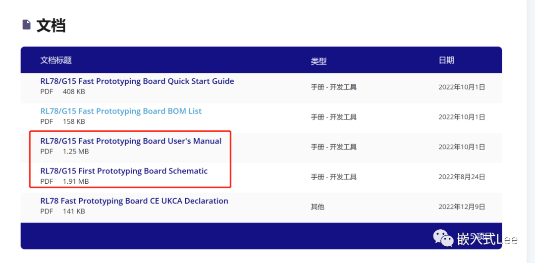
参考《RL78/G15 Fast Prototyping BoardUser’s Manual》
IO点灯
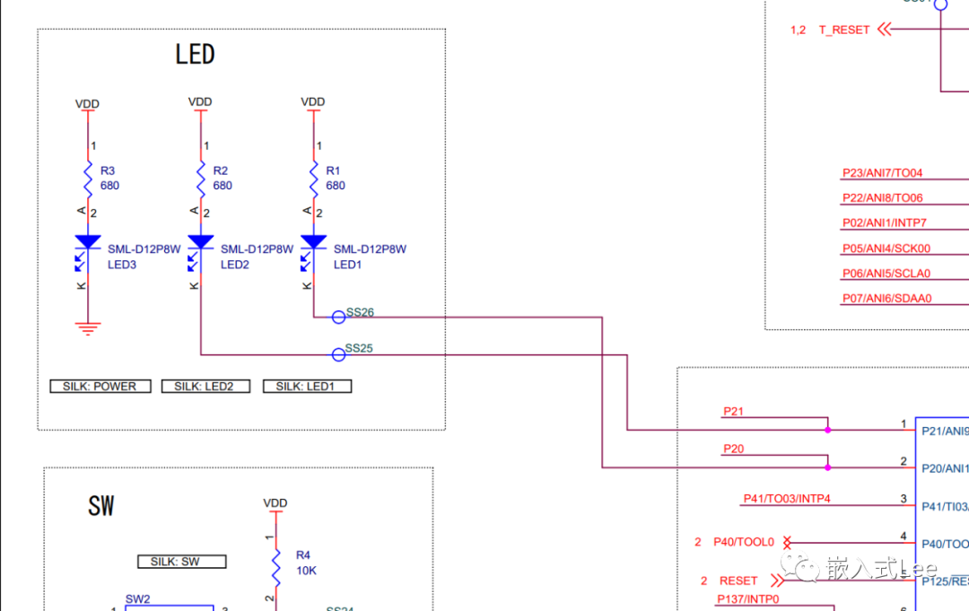
从原理图可以看到P20和P21控制LED2和LED1,低点亮。
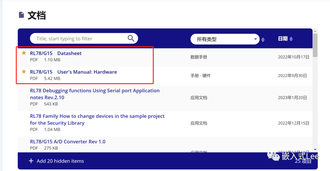
阅读《RL78/G15 User’s Manual: Hardware》的《CHAPTER 4 PORT FUNCTIONS》
和《CHAPTER 2 PIN FUNCTIONS》
寄存期
PM0/PM2/PM4/PM12:设置指定端口指定IO的输入输出,一个bit对应一个IO,0输出,1输入
P0, P2, P4, P12, P13:输出或读指定端口的指定IO的状态,一个bit对应一个IO。
PU0, PU2, PU4, PU12:设置指定端口指定IO的上拉电阻是否使能,一个bit对应一个IO,1使能,0不使能。必须满足以下条件
● PMmn = 1 (Input mode)
● PMCmn = 0 (Digital I/O)
● POMmn = 0 (Normal output mode)
POM0, POM2, POM4:设置指定端口指定IO的输出模式,一个bit对应一个IO,0正常模式,1开漏输出
PMC0, PMC2:设置指定端口指定IO的模数模式,一个bit对应一个IO,0数字端口,1模拟端口
PIOR0 to PIOR3:外设功能重定向。
配置代码
寄存器定义位于
iodefine.h
iodefine_ext.h
led.c中包含该头文件即可
#include"iodefine.h"
#include"iodefine_ext.h"
代码如下
/***************************************************************/
/* */
/* PROJECT NAME : led */
/* FILE : led.c */
/* DESCRIPTION : Main Program */
/* */
/* This file was generated by e2 studio. */
/* */
/***************************************************************/
int led_init(void)
{
PM2 &= ~(1u<<0); /*P20 out*/
P2 |= (1u<<0); /*P20 out 1*/
PU2 &= ~(1u<<0); /*P20 On-chip pull-up resistor not connected */
POM2 &= ~(1u<<0); /*P20 Normal output mode */
PMC2&= ~(1u<<0); /*P20 Digital I/O (alternate function other than analog input */
PM2 &= ~(1u<<1); /*P21 out*/
P2 |= (1u<<1); /*P21 out 1*/
PU2 &= ~(1u<<1); /*P21 On-chip pull-up resistor not connected */
POM2 &= ~(1u<<1); /*P21 Normal output mode */
PMC2&= ~(1u<<1); /*P21 Digital I/O (alternate function other than analog input */
return 0;
}
int led_set(int id,int value)
{
switch(id)
{
case 0:
if(value)
{
P2 &= ~(1u<<0); /*Set P20 output to low,LED1 on*/
}
else
{
P2 |= (1u<<0); /*Set P20 output to hight,LED1 off*/
}
break;
case 1:
if(value)
{
P2 &= ~(1u<<1); /*Set P20 output to low,LED2 on*/
}
else
{
P2 |= (1u<<1); /*Set P21 output to hight,LED2 off */
}
break;
default:
break;
}
return 0;
}
int led_delay(int t)
{
volatile int cycle = 100;
for(int i=0; i{
cycle = 100;
while(cycle-- > 0);
}
return 0;
}
int main(void) {
led_init();
while(1) {
// TODO: add application code here
led_set(0,1);
led_set(1,1);
led_delay(100);
led_set(0,0);
led_set(1,0);
led_delay(100);
}
return 0;
};>
仿真调试
编译

下载

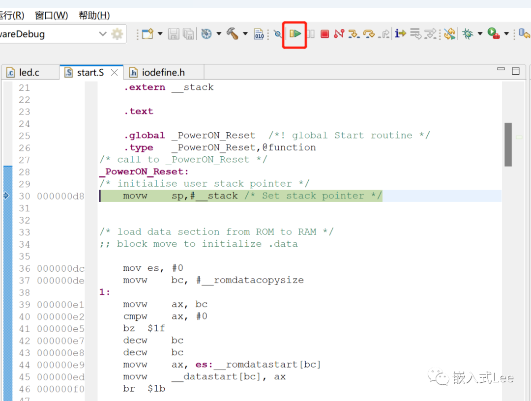
暂停在了复位代码处
运行
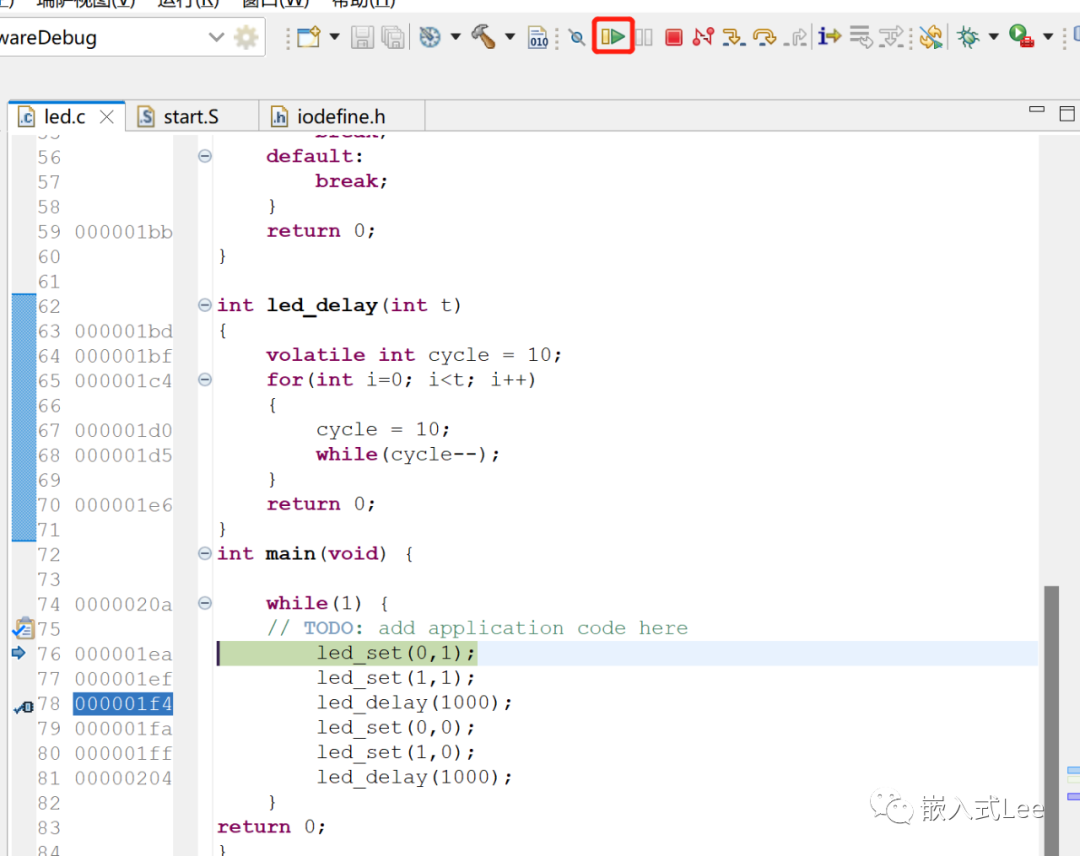
停在了main函数的断点处,继续运行
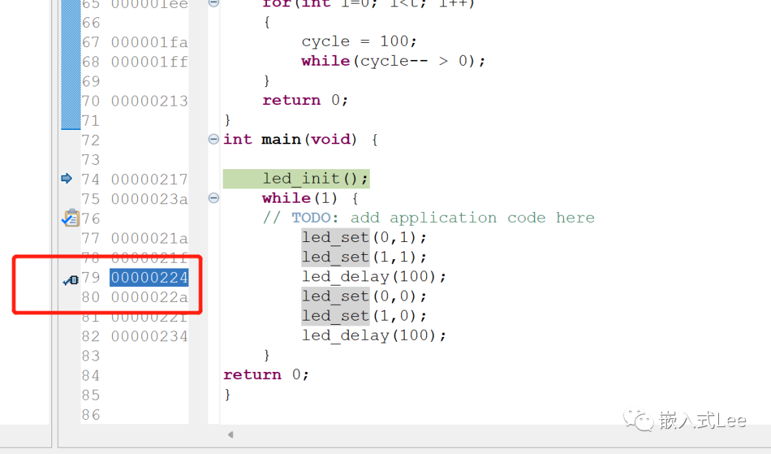
可以看到LED1和LED2闪烁
可以在指定位置双击打断点
查看对应的寄存器
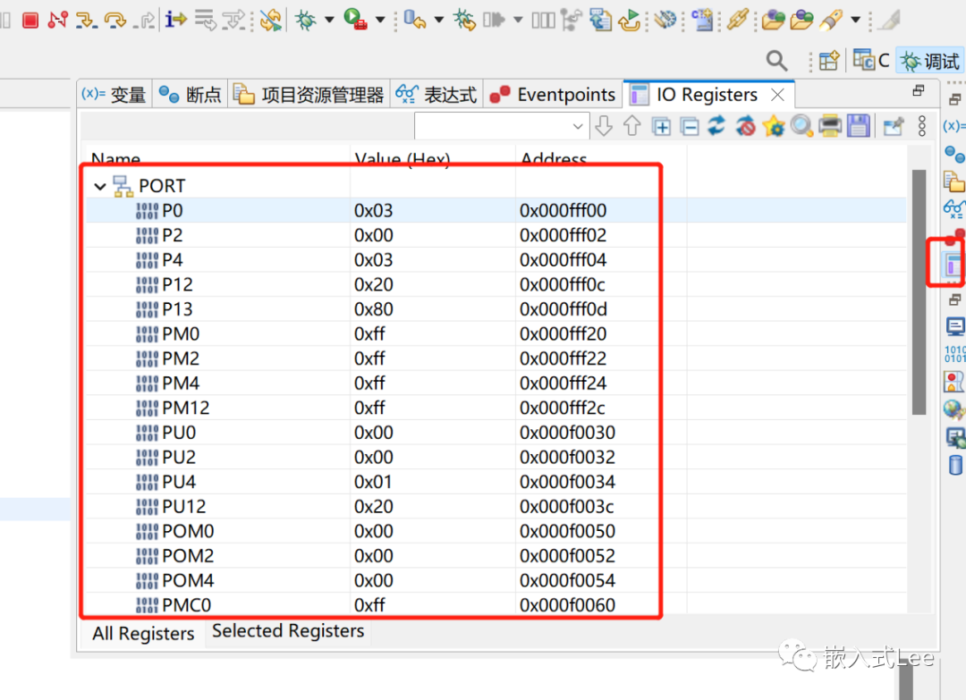
参考
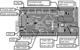
开发板资源
https://www.renesas.cn/cn/zh/products/microcontrollers-microprocessors/rl78-low-power-8-16-bit-mcus/rtk5rlg150c00000bj-rl78g15-fast-prototyping-board
主要下载查看User's manual用户手册和Schematic原理图。
MCU资料
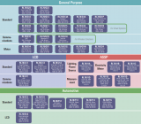
https://www.renesas.cn/cn/zh/products/microcontrollers-microprocessors/rl78-low-power-8-16-bit-mcus/rl78g15-compact-low-pin-count-microcontrollers-rich-peripheral-functions-general-purpose-applications
主要下载查看Datasheet数据手册和User’S Manual用户手册,编程主要参考后者,其他按需参考。
总结
以上step by step,介绍了RL78/G15开发板及其资源,搭建了开发环境并直接根据手册配置寄存器进行了点灯测试,介绍了仿真调试。入门RL78/G15开发,这一篇就够了。通过以上体验,总结如下:
1.开发板未提供MicroUSB线,最好能提供,这样开箱即可使用。
2.e2 studio基于eclipse整体而言入手比较简单。
3.板载调试器这一点非常方便。
4.官方开发文档资料非常详细。
5.还可以跑RTOS μITRON,不过这里还没试 参见https://www.renesas.cn/cn/zh/software-tool/ri78v4-v2-real-time-os-rl78-family。
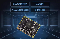
6.封装小,适合各种低成本低功耗应用场景。
7.开发工具开发方式比较简单。
1
END
1
-
mcu
+关注
关注
147文章
18605浏览量
387048 -
瑞萨
+关注
关注
36文章
22429浏览量
89751
发布评论请先 登录
探索 KunLun Pi | 基于匠芯创D13x系列开发板分享(三)

新时达STEP 2.0全新战略升级
ESP32-P4-MINI开发板开箱和上手指南来了!速速码住!

【RA-Eco-RA6M4开发板评测】+01+开箱测评+UART+PWM+LED
【嘉楠堪智K230开发板试用体验】+开箱测评+通电及点灯
【新品】远距离图传数传模块开发板、蓝牙模块开发板、无线模块开发板

PPS在做20mV step调压时,每个step之间的电压变化是否有时间要求?
【RA-Eco-RA4M2开发板评测】开箱 + 点灯
【RA-Eco-RA4M2开发板评测】开箱+Keil环境搭建+点灯
如何在VS Code中使用瑞萨RL78系列MCU
通过Boot swap实现瑞萨RL78/F24 MCU固件升级


 工商网监
工商网监
评论