 如何对MAX22007可配置模拟输出进行编程

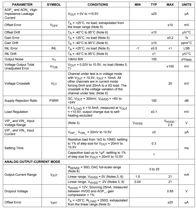
MAX22007为可配置模拟输出器件。它支持4个通道,每个通道可单独编程为0V至+10V电压输出或0mA至+20mA电流输出。
微控制器兼容型串行外设接口(SPI)提供对许多高级功能的访问。本应用笔记提供了在微控制器中实现设置、监控和诊断功能的C代码示例。
介绍
MAX22007集成了4个12位DAC(数模转换器),可创建4个通道,输出为软件可配置,支持0V至+10V或0mA至+20mA模拟输出。每个通道还可以检测负载阻抗,并确定负载是电压还是电流输入。
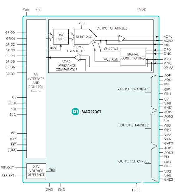
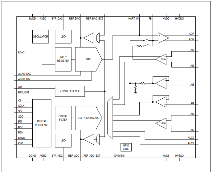
图1.MAX22007功能框图
本应用笔记阐述了一系列功能,以便对MAX22007进行更快、更成熟的编程。这些功能是用C语言编写的,很容易移植到任何常见的微控制器。请参考MAX22007数据资料,了解MAX22007引脚、工作模式和控制寄存器的详细信息。
MAX22007 SPI
MAX22007串行外设接口(SPI)命令为24位(8位指令+16位数据),CRC禁用时为24位,CRC启用时为32位。表 1 显示了 SPI 命令结构。MAX22007的SPI模式为CPOL = 0 (CLK空闲 = 0)和CPHA = 0 (上升沿/第一沿对数据进行采样)。数据/命令必须首先以最高有效字节 (MSB) 计时。
| 地址 | 控制 | 数据 |
| 7 位 A[6:0],MSB 至最低有效字节 (LSB) | R/W 位,读取 = 1,写入 = 0 | 16 位 D[15:0],MSB 至 LSB |
MAX22007数据资料详细介绍了SPI读写周期、寄存器表和指令。
图1所示为MAX22007的主要功能块。有四个通道可以单独编程为电压或电流输出,以及一个带有SPI端口的控制逻辑,用于访问所有寄存器和硬件标志以进行诊断。
MAX22007支持8路逻辑电平GPIO(通用输入/输出),以简化需要电流隔离的系统。GPIO可以控制外部组件,如多路复用器、FET(场效应晶体管)或使能切换电源,或通过隔离栅回读数字信号。该器件还支持菊花链模式,这也减少了隔离设计所需的IO引脚数量。
源代码
本应用笔记提供C源代码示例,提供驱动器功能,用于访问MAX22007中的多个寄存器,以实现配置、控制和诊断功能。
请注意,配置寄存器 0x03 LD_CNFG[3:0](位 15 至 12)在上电时设置为 0。所有四个输出在LDAC引脚上发生高低转换时同时更新。如果通道要求透明并立即更新,请将LD_CNFG位设置为 1。
用于通道/模式选择的全局变量
      public enum Register_address
        {
            // All Registers
            REVISION_ID       = 0x00,
            STATUS_INTERRUPTS = 0x01,
            INTERRUPT_ENABLE  = 0x02,
            CONFIGURATION     = 0x03,
            CONTROL           = 0x04,
            CHANNEL_MODE      = 0x05,
            SOFT_RESET        = 0x06,
            CHANNEL0_DATA     = 0x07,
            CHANNEL1_DATA     = 0x08,
            CHANNEL2_DATA     = 0x09,
            CHANNEL3_DATA     = 0x0a,
            GPIO_CONTROL      = 0x0b,
            GPIO_DATA         = 0x0c,
            GPI_EDGE_CTRL     = 0x0d,
            GPI_EDGE_STATUS   = 0x0e,
        };

        public enum AOut_Mode
        {
            high_impedance = 0,
            AO_12V         = 1,
            AO_25mA        = 2,
            out_of_range1  = 3,
        };


//********************************************************************
//*
//* Function: MAX22007_read_register
//* Description: Read one Register from MAX22007
//*
//* Input: Register-Address (take from definitions in header-file)
//* Output: 16bit register content
//*
//* if CRC is enabled, then crc8-Command is required
//*
//********************************************************************/
public UInt32 MAX22007EVKIT_read_register(Register_address address)
{
     if (CRC_Enabled == false)
     {
         max22007_port.SPI_CS0Enable();
         max22007_port.SPI_W_transaction_8( (ushort) ( ((byte)address << 1) + 0x01 )  );
         result = max22007_port.SPI_R_transaction_16();
         max22007_port.SPI_CS0Disable();
     }
     else
     {
         max22007_port.SPI_CS0Enable();
         max22007_port.SPI_W_transaction_8( (ushort) ( ((byte)address << 1) + 0x01 )  );
         result = max22007_port.SPI_R_transaction_16();
         max22007_port.SPI_CS0Disable();

         CRC_result = max22007_port.SPI_R_transaction_8();  // read the CRC
         byte CRC_TX1 = (address << 1) + 0x01;
         byte CRC_RX1 = ((result >> 8) & 0xff);
         byte CRC_RX2 = ((result     ) & 0xff);
         byte CRC_Calc = crc8(CRC_TX1, CRC_RX1, CRC_RX2);

         if (CRC_Calc != CRC_result)
         {
            result = 0xfffffffe; // return a 32 bit value to flag an error
         }
     }
}


//********************************************************************
//*
//* Function: MAX22007_write_register
//* Description: Write one Register to MAX22007
//*
//* Input: Register-Address (take from definitions in header-file)
//*        16bit data (new register content)
//*
//********************************************************************/
public void MAX22007EVKIT_write_register(Register_address address, UInt16 data)
{
    byte CRC_TX1 = (byte)((byte)address << 1);

    if (CRC_Enabled == false)
    {
        max22007_port.SPI_CS0Enable();
        max22007_port.SPI_W_transaction_8( (ushort) ( ((byte)address << 1) )  );
        max22007_port.SPI_W_transaction_16(data);
        max22007_port.SPI_CS0Disable();
    }
    else
    {
        byte CRC_TX2 = (byte)((data>> 8) & 0xff);
        byte CRC_TX3 = (byte)( data      & 0xff);
        byte CRC_Calc = crc8(CRC_TX1, CRC_TX2, CRC_TX3);

        max22007_port.SPI_CS0Enable();
        max22007_port.SPI_W_transaction_8( (ushort) ( ((byte)address << 1) )  );
        max22007_port.SPI_W_transaction_16(data);
        max22007_port.SPI_W_transaction_8( CRC_Calc );
        max22007_port.SPI_CS0Disable();
    }
}


// ********************************************************************
//
// Function: MAX22007_Mode_Set
// Description: Sets up MAX22007 Mode for one of the 4 Channels
//
// Input: mode:    Desired Mode
//        Channel: Desired Channel
// Output: None (The selected channel of MAX22007 will be setup by this routine)
//
// ********************************************************************
private void MAX22007_Mode_Set(byte Channel, AOut_Mode mode)
{
   // Set AO Mode (Register 0x05: CHANNEL_MODE)
   UInt32 previous_mode = MAX22007EVKIT_read_register(Register_address.CHANNEL_MODE);
   UInt16 new_mode = (UInt16) previous_mode;

   switch (Channel)
   {
     case 0:
              if (mode == AOut_Mode.high_impedance)
              {   new_mode = (new_mode & 0xeeff);   // High-Impedance, set to Voltage Mode and Power-Off - Channel 0
              }
              if (mode == AOut_Mode.AO_12V)
              {   new_mode = (new_mode & 0xefff);   // Voltage Output, set CHNL_MODE to 1 for this         Channel 0
                  new_mode = (new_mode | 0x0100);   // make sure the Channel is enabled                    Channel 0
              }
              if (mode == AOut_Mode.AO_25mA)
              {   new_mode = (new_mode | 0x1000);   // Current Output, set CHNL_MODE to 1 for this         Channel 0
                  new_mode = (new_mode | 0x0100);   // make sure the Channel is enabled                    Channel 0
              }
              break;
     case 1:
              if (mode == AOut_Mode.high_impedance)
              {   new_mode = (new_mode & 0xddff);   // High-Impedance, set to Voltage Mode and Power-Off - Channel 1
              }
              if (mode == AOut_Mode.AO_12V)
              {   new_mode = (new_mode & 0xdfff);   // Voltage Output, set CHNL_MODE to 1 for this         Channel 1
                  new_mode = (new_mode | 0x0200);   // make sure the Channel is enabled                    Channel 1
              }
              if (mode == AOut_Mode.AO_25mA)
              {   new_mode = (new_mode | 0x2000);   // Current Output, set CHNL_MODE to 1 for this         Channel 1
                  new_mode = (new_mode | 0x0200);   // make sure the Channel is enabled                    Channel 1
              }
              break;
     case 2:
              if (mode == AOut_Mode.high_impedance)
              {   new_mode = (new_mode & 0xbbff);   // High-Impedance, set to Voltage Mode and Power-Off - Channel 2
              }
              if (mode == AOut_Mode.AO_12V)
              {   new_mode = (new_mode & 0xbfff);   // Voltage Output, set CHNL_MODE to 1 for this         Channel 2
                  new_mode = (new_mode | 0x0400);   // make sure the Channel is enabled                    Channel 2
              }
              if (mode == AOut_Mode.AO_25mA)
              {   new_mode = (new_mode | 0x4000);   // Current Output, set CHNL_MODE to 1 for this         Channel 2
                  new_mode = (new_mode | 0x0400);   // make sure the Channel is enabled                    Channel 2
              }
              break;
     case 3:
              if (mode == AOut_Mode.high_impedance)
              {   new_mode = (new_mode & 0x77ff);   // High-Impedance, set to Voltage Mode and Power-Off - Channel 3
              }
              if (mode == AOut_Mode.AO_12V)
              {   new_mode = (new_mode & 0x7fff);   // Voltage Output, set CHNL_MODE to 1 for this         Channel 3
                  new_mode = (new_mode | 0x0800);   // make sure the Channel is enabled                    Channel 3
              }
              if (mode == AOut_Mode.AO_25mA)
              {   new_mode = (new_mode | 0x8000);   // Current Output, set CHNL_MODE to 1 for this         Channel 3
                  new_mode = (new_mode | 0x0800);   // make sure the Channel is enabled                    Channel 3
              }
                    break;
    }
    MAX22007EVKIT_write_register(Register_address.CHANNEL_MODE,  new_mode);
}

// ********************************************************************
//
// Function: MAX22007_convert_Voltage_to_LSB
// Description: Converts a voltage to an LSB value for the DAC
//
// Input:  float:  Voltage
// Output: UInt16  LSB Value for the DAC
//
// ********************************************************************
private UInt16 MAX22007_convert_Voltage_to_LSB (float voltage)
{
    UInt16 new_hex_value = 0;
    float result = 0;
    float phy_AO_12V_factor  = (float) 12.5 / (float) 4095;

    // check for errors
    if (voltage > 12.5)    { return 0xfffe; } // return out of range value to highlight there was an error
    if (voltage < 0)       { return 0xfffe; } // return out of range value to highlight there was an error

    // convert voltage to LSB value
    result = (voltage / phy_AO_12V_factor);
    new_hex_value = (UInt16) result;

    return new_hex_value;
}


// ********************************************************************
//
// Function: MAX22007_convert_Current_to_LSB
// Description: Converts a current in mA to an LSB value for the DAC
//
// Input:  float:  Current in mA
// Output: UInt16  LSB Value for the DAC
//
// ********************************************************************
private UInt16 MAX22007_convert_Current_to_LSB (float current_mA)
{
    UInt16 new_hex_value = 0;
    float result = 0;
    float phy_AO_25mA_factor = (float) 25 / (float) 4095;

    // check for errors
    if (current_mA > 25)    { return 0xfffe; } // return out of range value to highlight there was an error
    if (current_mA < 0)     { return 0xfffe; } // return out of range value to highlight there was an error

    // convert voltage to LSB value
    result = (current_mA / phy_AO_25mA_factor);
    new_hex_value = (UInt16) result;

    return new_hex_value;
}

// ********************************************************************
//
// Function: MAX22007_DAC_Set_LSB
// Description: Writes a new LSB value to the DAC,
//              assuming it is already setup in a specific mode, use DAC_Setup first
//              If LDAC-pin is high, it must be toggled after setting up update the output
//
// Input: new DAC value in LSB
// Output: None
//
// ********************************************************************
private void MAX22007_Set_DAC(byte Channel, UInt16 LSB_code)
{
  UInt16 DAC_out_register = (UInt16) (LSB_code << 4); // Shift bits to match with register

  switch (Channel)
  {
   case 0:
            MAX22007EVKIT_write_register (Register_address.CHANNEL0_DATA, DAC_out_register); // Write AO Data register CH0
            break;
   case 1:
            MAX22007EVKIT_write_register (Register_address.CHANNEL1_DATA, DAC_out_register); // Write AO Data register CH1
            break;
   case 2:
            MAX22007EVKIT_write_register (Register_address.CHANNEL2_DATA, DAC_out_register); // Write AO Data register CH2
            break;
   case 3:
            MAX22007EVKIT_write_register (Register_address.CHANNEL3_DATA, DAC_out_register); // Write AO Data register CH3
            break;
  }

}


// ********************************************************************
//
// Function: main
// Description: The follwoing function would setup:
//              1. ALL outputs to immediately update on write
//              2. Channel 0 in Voltage mode and drive 5V
//              3. Channel 1 in Current mode and drive 10mA
//
// Input:  float:  Current in mA
// Output: UInt16  LSB Value for the DAC
//
// ********************************************************************
private void setup_main ()
{
    MAX22007EVKIT_write_register (Register_address.CONFIGURATION, 0xf000);       // Set all Latch bits

    MAX22007_Mode_Set(0, AOut_Mode.AO_12V);                          // setup Channel 0 to Voltage Mode
    MAX22007_Mode_Set(1, AOut_Mode.AO_25mA);                         // setup Channel 1 to Current Mode

    UInt16 DAC_LSB_value = 0;

    DAC_LSB_value = MAX22007_convert_Voltage_to_LSB ((float) 5.0);   // get integer value for 5.0 Volt
    MAX22007_Set_DAC(0, DAC_LSB_value);                              // write this 5V value to Channel 0

    DAC_LSB_value = MAX22007_convert_Current_to_LSB ((float)10.0);   // get integer value for 10.0 mA
    MAX22007_Set_DAC(1, DAC_LSB_value);                              // write this 10.0mA value to Channel 1

}


// ********************************************************************
//
// Function: MAX22007_GPIO_Setup
// Description: Sets up all 8 GPIO Pins, bit0=GPIO0, bit1=GPIO1, ...
//              Since the command includes everything Enable/Disable as well as
//              GPIO Direction, this function is faster than GPO_Set
//              because it does not have to read back the setup from the part
//
// Input:  GPIO_enable (byte)    Bit0 = GPIO0, Bit1 = GPIO1, ... (0 = Off,   1 = On)
//         GPIO_direction (byte) Bit0 = GPIO0, Bit1 = GPIO1, ... (0 = Input, 1 = Output)
//
// Output: None
//
// ********************************************************************
void MAX22007_GPIO_Setup (byte GPIO_enable, byte GPIO_direction)
{
    UInt16 new_gpio_value = (UInt16) ( ( (GPIO_enable & 0xff) << 8) + ( (GPIO_direction & 0xff) ) );
    MAX22007EVKIT_write_register(Register_address.GPIO_CONTROL,  new_gpio_value);
}


// ********************************************************************
//
// Function: MAX22007_GPO_Set
// Description: Sets GPOs high or low, bit0=GPIO0, bit1=GPIO1, ...
//              GPOs must be setup and enabled prior this use MAX22007_GPO_Set
//
// Input: GPO Setting, bit0=GPIO0, bit1=GPIO1, ... (0 = Low, 1 = High)
// Output: None
//
// ********************************************************************
void MAX22007_GPO_Set (byte GPO_Setting)
{
    UInt16 GPO_data = (UInt16) ((GPO_Setting<<8) & 0xff00);                  // Shift bits for GPO

    MAX22007EVKIT_write_register(Register_address.GPIO_DATA, GPO_Setting);   // Write new GPO settings
                                                                             // Inputs are read only, no need to
                                                                             // worry about writing these bits
}

// ********************************************************************
//
// Function: MAX22007_GPI_Get
// Description: Gets all GPI readings high or low, bit0=GPIO0, bit1=GPIO1, ...
//              GPIs must be setup and enabled prior this use MAX22007_GPI_Get
//
// Input: None
// Output: GPI Setting, bit0=GPIO0, bit1=GPIO1, ... (0 = Low, 1 = High)
//
// ********************************************************************
byte  MAX22007_GPI_Get ()
{
    UInt32 gpi_result = MAX22007EVKIT_read_register(Register_address.GPIO_DATA);  // read GPI Data
    byte result = (byte) (gpi_result & 0xff);

    return result;
}
结直肠功能
AN7072 中更详细地描述了具有 24 位寄存器的器件的 CRC 功能和计算。MAX22007只有16位寄存器。AN7072中的CRC计算与MAX22007的概念相同,但计算结果仅为3个字节,而不是AN7072中描述的4个字节。以下功能可按原样用于MAX22007。
// ********************************************************************
//
// Function: MAX22007_crc8
// Description: Calculates CRC for MAX22007 commands (read or write)
//
// Input: BYTE1:     Command byte (register address + R/W bit)
//        BYTE2:     MS-Byte of the register value
//        BYTE3:     LS-Byte of the register value
// Output byte:      crc8 of Input
//                   -> for write commands send result as the CRC code
//                   -> for read commands compare result to check for errors
//
// ********************************************************************
public byte MAX22007_crc8(byte BYTE1, byte BYTE2, byte BYTE3)
{
    byte crc8_start = 0x00;
    byte crc8_poly  = 0x8c; // rotated 0x31, which is our polinomial
    byte crc_result = crc8_start;

    // BYTE1
    for (int i=0; i<8; i++)
    {
        if( ( (( BYTE1>>i ) ^ (crc_result) ) & 0x01 ) > 0 )      // IF(XOR(C6;BITAND(D5;2^4)/2^4)
        { crc_result = (byte) (crc8_poly ^ crc_result>>1 );  }   // BITXOR($D$1;BITAND((D5*2);31))
        else
        { crc_result = (byte) (crc_result>>1);               }
    }

    // BYTE2
    for (int i=0; i<8; i++)
    {
        if( ( (( BYTE2>>i ) ^ (crc_result) ) & 0x01 ) > 0 )      // IF(XOR(C6;BITAND(D5;2^4)/2^4)
        { crc_result = (byte) (crc8_poly ^ crc_result>>1 );  }   // BITXOR($D$1;BITAND((D5*2);31))
        else
        { crc_result = (byte) (crc_result>>1);               }
    }

    // BYTE3
    for (int i=0; i<8; i++)
    {
        if( ( (( BYTE3>>i ) ^ (crc_result) ) & 0x01 ) > 0 )      // IF(XOR(C6;BITAND(D5;2^4)/2^4)
        { crc_result = (byte) (crc8_poly ^ crc_result>>1 );  }   // BITXOR($D$1;BITAND((D5*2);31))
        else
        { crc_result = (byte) (crc_result>>1);               }
    }
    return crc_result;
}
结论
本应用笔记介绍了如何针对所有可能的用例对MAX22007进行编程。MAX22007评估板用于测试该代码。本应用笔记中的C代码示例是一种经过验证的解决方案,可在常用微控制器和MAX22007之间快速、轻松地实现接口。
审核编辑:郭婷
-
微控制器
+关注
关注
48文章
8255浏览量
162461 -
阻抗
+关注
关注
17文章
983浏览量
48768 -
SPI
+关注
关注
17文章
1866浏览量
99848 -
数模转换器
+关注
关注
14文章
1284浏览量
85209 -
GPIO
+关注
关注
16文章
1313浏览量
55733
发布评论请先 登录
用于可编程逻辑控制器 (PLC) 的 16 位模拟输出模块参考设计
支持可配置安徽模拟输出的大时代传感器可靠吗
如何设计通用模拟输出

兼容I2C总线和可配置模拟输出的PAC192
如何构建环路供电的模拟输出

如何对MAX22000可配置模拟IO进行编程
MAX22007PMB: MAX22007 Peripheral Module Data Sheet MAX22007PMB: MAX22007 Peripheral Module Data Sheet

软件可配置模拟 I/O 的设计理念
MAX22007集成基准电压源的四通道12位可配置模拟输出器件技术手册


 工商网监
工商网监
评论