 一文详解halcon图像拼接技术

图像拼接技术就是针对同一场景的一系列图片,根据图片的特征,比如位置,重叠部分等,拼接成一张大幅的宽视角的图像。
图像拼接要求拼接后图像最大程度的与原图一致,失真尽可能的小,并且要尽量做到天衣无缝即没有明显的拼接线或其他拼接痕迹。
图像拼接不能损失原始图像信息
为达到以上目标,图像拼接要求具备以下条件:
1:图像应具有一定的特征性能,拼接正是通过这些特征来进行的。
2:图像需要具有重叠部分,一般情况下,这些重叠部分点图像的1/4以上较为合理。
3、图像的背景亮度差异不能太大,应该低于10个灰度值,否则难以拼接成功。
4、图像的方位差异不能太大,图像应该来源同一方位。
5、拼合边界过渡应平滑,以消除接拼痕迹
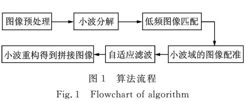
图像拼接前,根据图像情况,可以进行图像预处理,主要是对图像进行校正和噪声滤波
1、校正
根据图像失真原因,建立相应的校正模型,从失真的图像中提取所需要的信息。从图像失真的逆过程来恢复图像。这个过程也可以理解为设计一个滤波器,使用其能从失真图像中计算得到真实图像的估值,从而最大程度的恢复真实图像。
2、噪声滤波
噪声在图像上分布主要有两种型式:
1、位置随机,幅值基本相同,一般称之为 椒盐噪声;
2、幅值随机,但基本上每个点都存在,从幅值的分布统计来看,主要有高斯型,瑞利型,又有如频谱均匀的噪声。
对于这些噪声,处理方法有如下几种:
1、均值滤波
就是用均值替代原图像中的各个像素。具体方法是:对将处理的像素,选择一个模板,此模板为其邻近的若干像素组成,用模板中的像素的均值去替代原来的像素值 。
2、中值滤波
中值滤波是一种非线性平滑技术,它将每一像素点的灰度值设置为该点某邻域窗口内的所有像素点灰度值的中值. 中值滤波是基于排序统计理论的一种能有效抑制噪声的非线性信号处理技术,中值滤波的基本原理是把数字图像或数字序列中一点的值用该点的一个邻域中各点值的中值代替,让周围的像素值接近的真实值,从而消除孤立的噪声点。方法是用某种结构的二维滑动模板,将板内像素按照像素值的大小进行排序,生成单调上升(或下降)的为二维数据序列。二维中值滤波输出为g(x,y)=med{f(x-k,y-l),(k,l∈W)} ,其中,f(x,y),g(x,y)分别为原始图像和处理后图像。W为二维模板,通常为3*3,5*5区域,也可以是不同的的形状,如线状,圆形,十字形,圆环形等。
图像配比:
包含以下几个要素
1、选定特征空间
特征空间是由不参与匹配的图像特征构成。特征可以为图像的灰度特征,也可以是边界,轮廓,显著特征(如角点,线交叉点,高曲率点),统计特征(如矩不变量,中心),高层结构描述与句法描述等;这里其实是定义了配准的空间范围。
2、相似度
评估待匹配特征之间的相似性,它通常定义为某种代价函数或者是距离函数。这里定义为需要选定的某种算法。
3、搜索空间
待估计参数组成的空间就称为搜索空间,也就是说,搜索空间是指所有可能的变换组成的空间。这其实就定义了搜索算法的空间复杂度
4、搜索策略
用合适的方法在搜索空间中找出平移,旋转等变换参数的最佳估计,使得相似度达到最大值,这其实也就是定义了搜索算法的时间复杂度。
拼接方法:
1、基于区域的配准方法
采用拼接图像的灰度值检测,对待配准图你中一块区域与参考图像中的相机尺寸的区域使用最小二乘法或者其它数学方法计算其灰度值的差异,对此差异比较后来判断待拼接图像重叠区域的相似度,由此得到待拼接图像重叠区域的范围和位置,从而实现图像拼接。也可以通过FFT变换将图像由时域变换到频域,然后再进行配准。对位移量比较大的图像,可以先校正图像的旋转,然后建立两幅图像之间的映射关系,总而言之,这种方法有很多不足,已经不是主流了。
2、基于特征的配准方法
基于特征的图像配准方法有很多形式及其改进方式,其总体特点是:不直接利用图像的像素,而是通过像素值导出图像内容最抽像的描述和符号特征,并用此特征为匹配模板,通过二维高斯模糊过滤,把几幅待配准图像的灰度局总最大值,边界边缘轮廓,边缘点,边缘线段,组织(纹理)结构,角、项点,拐点,交叉点,封闭曲线低级对应特征点及利用特征图像关系图等高级特征,构造方程组,通过数值计算得到变换数来进行图像对齐,进而确定两者的匹配位置,实现特征点,特征线等拼接,并且可以提高运算速度。
基于特征的接拼方法,分为四个步骤
1、特征检测:从图像中检测出显著且独特的图像特征,诸如:闭合区域,直线段,边缘,轮廓,点等。
2、特征匹配:从相似度确定图像之间特征的对应关系,又分为如下几类:
2.1:使用空域关系的方法
2.2:使用不变描述符的方法
2.3:松弛方法
2.4:金字塔和小波方法
3、变换模型的估计:变换函数选择和函数参数估计
4、图像变换和重采样:可以通过前向或后向的方式来实现,插值的方法有最近邻插值、双线性插值、双三次函数插值、二次样条插值、三次B样条插值、高阶B样条插值。
基于特征的方法普遍适用于局部结构信息更显著
的情况,能够处理图像之间复杂变形的情况,不足之处是特征检测困难且不稳定,最关键的一点是需要有一种判断力很强的、鲁棒性能好的且对图像之间变化保持不变的特征匹配算法。
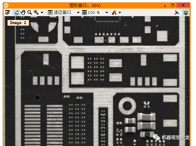
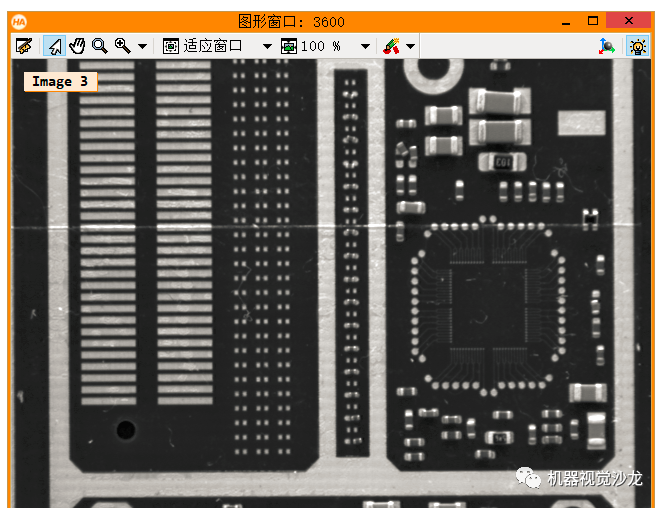
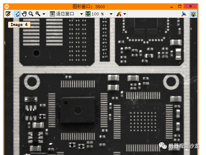
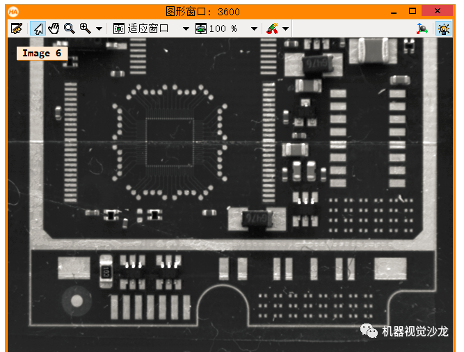
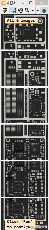
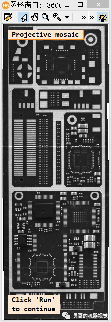
下面是Halcon自带例程,如何拼接图像
**此例程讲解了如何将几张局部的PCB图像拼接居一张大的马赛克PCB图像。
**此例程使用算子proj_match_points_ransac和算子 gen_projective_masaic完成上述工作。
**请注意:这个PCB图像有一几处看起来像拼接逢合线的破损点,为了更好的区分真正的缝合线,例程呈现逢合线。
dev_update_off ()
dev_close_window ()
dev_open_window (0, 0, 640, 480, 'white', WindowHandle)
dev_set_color ('green')
set_display_font (WindowHandle, 14, 'mono', 'true', 'false')
**一张一张的读取图像。
gen_empty_obj (Images)
for J := 1 to 6 by 1
    read_image (Image, 'mosaic/pcb_' + J$'02')
    concat_obj (Images, Image, Images)
    dev_display (Image)
    disp_message (WindowHandle, 'Image ' + J$'d', 'image', -1, -1, 'black', 'true')
    wait_seconds (1)
endfor
disp_continue_message (WindowHandle, 'black', 'true')
stop ()
* To show the point matches that are used to compute the projective
* transformation between the images, we will show all images in a large
* tiled image with some space between the images so that the extents
* of the images are easily visible.
dev_set_window_extents (-1, -1, 640 / 4, 2980 / 4)
tile_images_offset (Images, TiledImage, [0,500,1000,1500,2000,2500], [0,0,0,0,0,0], [-1,-1,-1,-1,-1,-1], [-1,-1,-1,-1,-1,-1], [-1,-1,-1,-1,-1,-1], [-1,-1,-1,-1,-1,-1], 640, 2980)
dev_clear_window ()
dev_display (TiledImage)
disp_message (WindowHandle, 'All 6 images', 'window', 12, 12, 'black', 'true')
disp_message (WindowHandle, 'Click 'Run'
to continue', 'window', 2980 / 4 - 50, 12, 'black', 'true')
stop ()
* Now we compute point matches between the five pairs of images and with this
* the projective transformation between the image pairs.  Note that the code
* below calls the point operator for each image pair.  Since the images form
* a strip, with a little book keeping we could make the process a little more
* efficient by saving the points from the last iteration (ImageT in pair J will
* be identical to ImageF in pair J+1).  This is not done here because such an
* optimization would be quite cumbersome in the general case where the images
* can lie in a general configuration that cannot be represented by a strip.
dev_clear_window ()
dev_display (TiledImage)
disp_message (WindowHandle, 'Point matches', 'window', 12, 3, 'black', 'true')
* We define the image pairs, i.e., which image should be mapped to which image.
From := [1,2,3,4,5]
To := [2,3,4,5,6]
Num := |From|
* We need a variable to accumulate the projective transformation matrices.
ProjMatrices := []
* Furthermore, since we want to create a rigid mosaic below we need to
* accumulate all the point correspondences and the number of matches per
* image pair.
Rows1 := []
Cols1 := []
Rows2 := []
Cols2 := []
NumMatches := []
* Now we can determine the transformations between the five image pairs.
for J := 0 to Num - 1 by 1
    F := From[J]
    T := To[J]
    select_obj (Images, ImageF, F)
    select_obj (Images, ImageT, T)
    * Extract the points in both images.
    points_foerstner (ImageF, 1, 2, 3, 200, 0.3, 'gauss', 'false', RowJunctionsF, ColJunctionsF, CoRRJunctionsF, CoRCJunctionsF, CoCCJunctionsF, RowAreaF, ColAreaF, CoRRAreaF, CoRCAreaF, CoCCAreaF)
    points_foerstner (ImageT, 1, 2, 3, 200, 0.3, 'gauss', 'false', RowJunctionsT, ColJunctionsT, CoRRJunctionsT, CoRCJunctionsT, CoCCJunctionsT, RowAreaT, ColAreaT, CoRRAreaT, CoRCAreaT, CoCCAreaT)
    * Determine the point matches and the transformation for the current
    * image pair.
    proj_match_points_ransac (ImageF, ImageT, RowJunctionsF, ColJunctionsF, RowJunctionsT, ColJunctionsT, 'ncc', 21, 0, 0, 480, 640, 0, 0.5, 'gold_standard', 1, 4364537, ProjMatrix, Points1, Points2)
    * Accumulate the transformation matrix.
    ProjMatrices := [ProjMatrices,ProjMatrix]
    * Accumulate the point matches and number of point matches.
    Rows1 := [Rows1,subset(RowJunctionsF,Points1)]
    Cols1 := [Cols1,subset(ColJunctionsF,Points1)]
    Rows2 := [Rows2,subset(RowJunctionsT,Points2)]
    Cols2 := [Cols2,subset(ColJunctionsT,Points2)]
    NumMatches := [NumMatches,|Points1|]
    * Generate crosses that represent the extracted points in the tiled image.
    * Note that we have to take the row offsets of the images in the tiled image
    * into account.
    gen_cross_contour_xld (PointsF, RowJunctionsF + (F - 1) * 500, ColJunctionsF, 6, rad(45))
    gen_cross_contour_xld (PointsT, RowJunctionsT + (T - 1) * 500, ColJunctionsT, 6, rad(45))
    * Generate a representation of the matched point pairs as lines.  We create
    * XLD contours from the lines so that we can zoom into the graphics window
    * to take a closer look at the matches.
    RowF := subset(RowJunctionsF,Points1) + (F - 1) * 500
    ColF := subset(ColJunctionsF,Points1)
    RowT := subset(RowJunctionsT,Points2) + (T - 1) * 500
    ColT := subset(ColJunctionsT,Points2)
    gen_empty_obj (Matches)
    for K := 0 to |RowF| - 1 by 1
        gen_contour_polygon_xld (Match, [RowF[K],RowT[K]], [ColF[K],ColT[K]])
        concat_obj (Matches, Match, Matches)
    endfor
    * Now display the extracted data.
    dev_set_color ('blue')
    dev_display (Matches)
    dev_set_color ('green')
    dev_display (PointsF)
    dev_display (PointsT)
endfor
disp_message (WindowHandle, 'Click 'Run'
to continue', 'window', 2980 / 4 - 50, 12, 'black', 'true')
stop ()
* Finally, we can generate the mosaic image from the projective transformations.
gen_projective_mosaic (Images, MosaicImage, 2, From, To, ProjMatrices, 'default', 'false', MosaicMatrices2D)
get_image_size (MosaicImage, Width, Height)
dev_set_window_extents (-1, -1, Width / 3, Height / 3)
dev_clear_window ()
dev_display (MosaicImage)
disp_message (WindowHandle, 'Projective mosaic', 'window', 12, 12, 'black', 'true')
disp_message (WindowHandle, 'Click 'Run'
to continue', 'window', Height / 3 - 50, 12, 'black', 'true')
stop ()
* To show more clearly that the folds visible in the image do not result from the
* mosaicking, we display the seams between the images in the mosaic image.
* This can be done most easily by creating an image that contains the border
* of the images, generating a mosaic from it, and segmenting the resulting
* mosaic image.
get_image_size (Image, Width, Height)
gen_image_const (ImageBlank, 'byte', Width, Height)
gen_rectangle1 (Rectangle, 0, 0, Height - 1, Width - 1)
paint_region (Rectangle, ImageBlank, ImageBorder, 255, 'margin')
gen_empty_obj (ImagesBorder)
for J := 1 to 6 by 1
    concat_obj (ImagesBorder, ImageBorder, ImagesBorder)
endfor
gen_projective_mosaic (ImagesBorder, MosaicImageBorder, 2, From, To, ProjMatrices, 'default', 'false', MosaicMatrices2D)
threshold (MosaicImageBorder, Seams, 128, 255)
dev_clear_window ()
dev_display (MosaicImage)
disp_message (WindowHandle, 'Seams between the
images', 'window', 12, 12, 'black', 'true')
dev_set_color ('yellow')
dev_display (Seams)
disp_message (WindowHandle, 'Click 'Run'
to continue', 'window', 550, 12, 'black', 'true')
stop ()
* If you look very closely at the projective mosaic above, you may note that
* there is a very slight projective distortion in the mosaic.  This happens
* because the transformations cannot be determined with perfect accuracy
* because of very small errors in the point coordinates due to noise.  Because
* of the strip configuration, essentially the overlapping area between the image
* pairs can act like a hinge around which the images may rotate out of the image
* plane.  In this example, we know that the mapping between the images must
* be a rigid transformation.  If we want to force the transformation to be rigid
* we can simply use bundle_adjust_mosaic.
bundle_adjust_mosaic (6, 1, From, To, ProjMatrices, Rows1, Cols1, Rows2, Cols2, NumMatches, 'rigid', MosaicMatrices2D, Rows, Cols, Error)
* Now, we can generate the mosaic image from the rigid transformations.
gen_bundle_adjusted_mosaic (Images, MosaicImageRigid, MosaicMatrices2D, 'default', 'false', TransMatrix2D)
get_image_size (MosaicImageRigid, Width, Height)
dev_set_window_extents (-1, -1, Width / 3, Height / 3)
dev_clear_window ()
dev_display (MosaicImageRigid)
disp_message (WindowHandle, 'Rigid mosaic', 'window', 12, 12, 'black', 'true')


下面我们看一下另一个例程:
这个例程使用proj_match_points_ransac_guided 和gen_projective_mosaic
主要介绍如何使用金字塔算法快速获取两个图像的特征点进行拼接。
* This example program shows how images can be combined
* into a mosaic image using proj_match_points_ransac_guided
* and gen_projective_mosaic.
* It is shown how the calculation of the projection between two
* images can be accelerated using an image pyramid.
*
* Initializations
ImgPath := '3d_machine_vision/mosaic/'
ImgName := 'bga_r_'
Times := []
Colors := ['red','coral','yellow','lime green']
read_image (Images, ImgPath + ImgName + ['01','06'])
dev_update_off ()
dev_close_window ()
dev_open_window_fit_size (0, 0, 640, 980, 320, 490, WindowHandle)
dev_open_window_fit_size (0, 330, 490, 490, 1000, 490, WindowHandle1)
set_display_font (WindowHandle, 14, 'mono', 'true', 'false')
set_display_font (WindowHandle1, 14, 'mono', 'true', 'false')
* The internal camera parameters of the used camera
* (necessary to eliminate radial distortions)
CamParam := [0.0121693,-2675.63,7.40046e-006,7.4e-006,290.491,258.887,640,480]
change_radial_distortion_cam_par ('adaptive', CamParam, 0, CamParOut)
change_radial_distortion_image (Images, Images, Images, CamParam, CamParOut)
* To show the point matches that are used to compute the
* transformation between the images, we will show both images in a
* tiled image with some space between the images so that the extents
* of the images are easily visible.
tile_images_offset (Images, TiledImage, [0,500], [0,0], [-1,-1], [-1,-1], [-1,-1], [-1,-1], 640, 980)
*
* Now we can determine the transformations between the image pairs.
From := 1
To := 2
select_obj (Images, ImageF, From)
select_obj (Images, ImageT, To)
*
* Repeat the calculation 4 times with a different number of pyramid levels
for NumLevels := 1 to 4 by 1
    *
    dev_clear_window ()
    dev_set_window (WindowHandle)
    dev_clear_window ()
    dev_display (TiledImage)
    disp_message (WindowHandle, ['Calculate point matches','with ' + NumLevels + ' pyramid levels','Please wait ...'], 'window', 20, 10, 'black', 'true')
    *
    * Calculate the projection between the two images
    * Check the procedure's comments for details
    count_seconds (S1)
    proj_match_points_ransac_pyramid (ImageF, ImageT, NumLevels, RowFAll, ColFAll, RowTAll, ColTAll, ProjMatrix, Points1, Points2)
    count_seconds (S2)
    Times := [Times,S2 - S1]
    *
    * Display point correspondences
    gen_cross_contour_xld (PointsF, RowFAll, ColFAll, 6, rad(45))
    gen_cross_contour_xld (PointsT, RowTAll + 500, ColTAll, 6, rad(45))
    RowF := subset(RowFAll,Points1)
    ColF := subset(ColFAll,Points1)
    RowT := subset(RowTAll,Points2) + 500
    ColT := subset(ColTAll,Points2)
    gen_empty_obj (Matches)
    for K := 0 to |RowF| - 1 by 1
        gen_contour_polygon_xld (Match, [RowF[K],RowT[K]], [ColF[K],ColT[K]])
        concat_obj (Matches, Match, Matches)
    endfor
    dev_display (TiledImage)
    dev_set_color ('blue')
    dev_display (Matches)
    dev_set_color ('green')
    dev_display (PointsF)
    dev_display (PointsT)
    disp_message (WindowHandle, [|RowF| + ' point matches','Time used: ' + (S2 - S1)$'.3' + ' s'], 'window', 20, 10, 'black', 'true')
    *
    * Generate the mosaic image
    gen_projective_mosaic (Images, MosaicImage, 1, From, To, ProjMatrix, [2,1], 'false', MosaicMatrices2D)
    *
    * Display mosaic image
    get_image_size (MosaicImage, Width, Height)
    dev_set_window (WindowHandle1)
    dev_resize_window_fit_image (MosaicImage, 0, 330, [400,700], 700)
    dev_clear_window ()
    dev_display (MosaicImage)
    disp_message (WindowHandle1, 'Projective mosaic (used ' + NumLevels + ' pyramid levels)', 'window', 20, 10, 'black', 'true')
    disp_continue_message (WindowHandle1, 'black', 'true')
    stop ()
endfor
*
* Display execution times
dev_set_window (WindowHandle)
dev_close_window ()
MaxTime := max(Times)
BaseRow := 380
RectHeight := 300
disp_message (WindowHandle1, ['Time in s:','(#levels used)'], 'image', BaseRow + 20, 10, 'black', 'true')
for Index := 0 to |Times| - 1 by 1
    gen_rectangle1 (Rectangle, BaseRow - RectHeight * Times[Index] / MaxTime, 200 + Index * 100, BaseRow, 280 + Index * 100)
    disp_message (WindowHandle1, [Times[Index]$'.3','(' + (Index + 1) + ')'], 'image', BaseRow + 20, 200 + 100 * Index, 'black', 'true')
    dev_set_color (Colors[Index])
    dev_set_draw ('fill')
    dev_display (Rectangle)
endfor
disp_finished_message (WindowHandle1, 'black', 'true')
审核编辑:汤梓红
-
拼接技术
+关注
关注
0文章
6浏览量
7486 -
图像拼接
+关注
关注
0文章
28浏览量
10988 -
HALCON
+关注
关注
17文章
66浏览量
28469
原文标题:halcon图像拼接技术
文章出处:【微信号:vision263com,微信公众号:新机器视觉】欢迎添加关注!文章转载请注明出处。
发布评论请先 登录


评论