0
  • 聊天消息
  • 系统消息
  • 评论与回复
登录后你可以
  • 下载海量资料
  • 学习在线课程
  • 观看技术视频
  • 写文章/发帖/加入社区
创作中心

完善资料让更多小伙伴认识你,还能领取20积分哦,立即完善>

3天内不再提示

将SIM900A与PIC微控制器连接起来实现GSM模块拨打和接听电话

科技观察员 来源:circuitdigest 作者:阿斯文斯·拉吉 2023-01-25 17:27 次阅读

GSM模块使用起来非常吸引人,尤其是当我们的项目需要远程访问时。这些模块可以执行我们普通手机可以执行的所有操作,例如拨打/接听电话,发送/接收短信,使用GPRS连接到互联网等。您还可以将普通麦克风和扬声器连接到此模块,并在移动通话中交谈。如果它可以与微控制器连接,这将为许多创意项目打开大门。因此,在本教程中,我们将学习如何将GSM模块(SIM900A)与我们的PIC微控制器连接,并通过使用GSM模块拨打和接听电话来演示它。

所需材料:

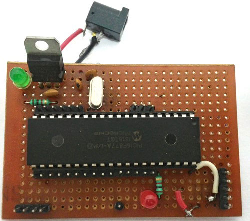
  1. PIC 微控制器 (PIC16F877A)
  2. GSM 模块(SIM900 或任何其他)
  3. 连接线
  4. 12V 适配器
  5. 图片套件 3

GSM模块:

GSM模块SIM900A

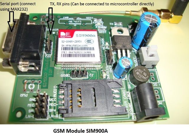
即使没有任何微控制器,也可以通过使用AT命令模式使用GSM模块。如上所示,GSM模块带有USART适配器,可以使用MAX232模块直接连接到计算机,或者Tx和Rx引脚可用于将其连接到微控制器。您还可以注意到可以连接麦克风或扬声器的其他引脚,如MIC +,MIC-,SP+,SP-等。该模块可以通过普通的直流桶形插孔由 12V 适配器供电

将SIM卡插入模块插槽并打开电源,您应该注意到电源指示灯亮起。现在等待一分钟左右,您应该会看到红色(或任何其他颜色)LED 每 3 秒闪烁一次。这意味着您的模块能够与您的SIM卡建立连接。现在,您可以继续将模块与手机或任何微控制器连接。

使用 AT 命令与 GSM 模块通信

正如您可能已经猜到的那样,GSM模块可以通过串行通信进行通信,并且只能理解一种语言,即“ AT命令 ”。无论您想告诉或询问GSM模块什么,都只能通过AT命令进行。例如,如果您想知道模块是否处于活动状态。您应该询问(发送)像“AT”这样的命令,您的模块将回答“确定”。

这些AT命令在其数据手册中有很好的解释,可以在其官方数据手册中找到。好!好!这是一份 271 页的数据表,您可能需要几天时间才能通读它们。因此,我在下面给出了一些最重要的AT命令,以便您尽快启动并运行它。

回复“确定”进行确认
AT+CPIN? 检查信号质量
AT+COPS? 查找服务提供商名称
ATD96XXXXXXXX; 拨打特定号码,以分号结尾
AT+CNUM 查找SIM卡的数量(可能不适用于某些SIM卡)
ATA 接听来电
阿特 挂断当前来电
AT+COLP 显示来电号码
AT+VTS=(数字) 发送 DTMF 编号。您可以使用移动键盘上的任意数字(数字)
AT+CMGR AT+CMGR=1 在第一个位置读取消息
AT+CMGD=1 删除第一个位置的消息
AT+CMGDA=“DEL ALL” 从SIM卡中删除所有邮件
AT+CMGL=“ALL” 读取来自 SIM 卡的所有消息
AT+CMGF=1 设置短信配置。“1”表示纯文本模式
AT+CMGS = “+91 968837XXXX”>电路摘要文本 在此处向特定号码发送短信 968837XXXX。当您看到“>”时,请开始输入文本。按 Ctrl+Z 发送文本。
AT+CGATT? 检查SIM卡上的互联网连接
AT+CIPSHUT 关闭TCP连接,意味着断开互联网
AT+CSTT = “APN”,“用户名”,“通行证” 使用您的 APN 和通行密钥连接到 GPRS。可以从网络提供商处获得。
AT+CIICR 检查SIM卡是否有数据包
AT+CIFSR 获取 SIM 卡网络的 IP
AT+CIPSTART = “TCP”,“服务器 IP”,“端口 用于设置 TCP IP 连接
AT+CIPSEND 此命令用于将数据发送到服务器

电路图:

GSM模块与PIC微控制器接口的连接图如下所示。
1.png

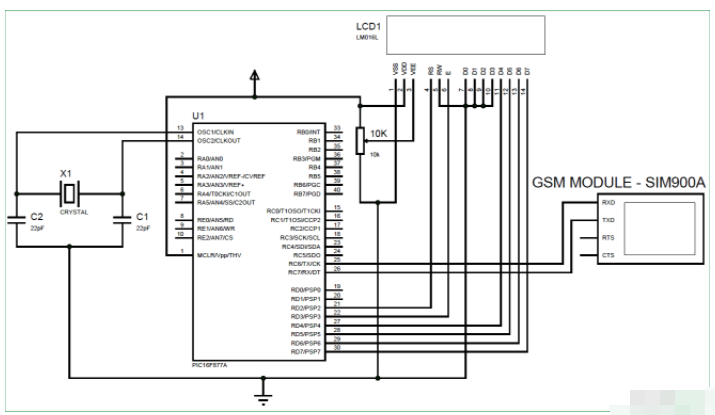
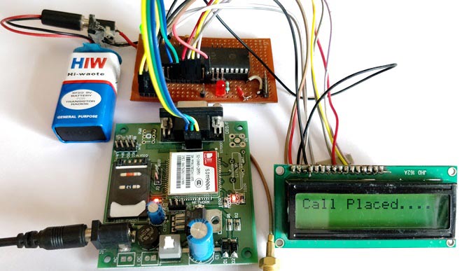
我们只是简单地将GSM模块的Tx和Rx引脚分别与PIC MCU PIC16F877A的Rx和Tx引脚连接。这将在两者之间建立串行连接。另外,不要忘记将GSM和PIC模块共同接地。我们还使用LCD显示屏来了解GSM模块的状态。连接完成后,您的硬件将如下所示。

使用 GSM 和 PIC 微控制器拨打和接听电话

用于PIC微控制器的PERF包教程

PIC微控制器编程

可以在本教程的底部找到此项目的完整程序。在这里,我将解释一些重要的函数和代码片段。该程序还具有LCD代码,该代码来自与PIC微控制器的接口LCD,如果您想知道如何将LCD与PIC微控制器一起使用,可以访问该教程。

如前所述,我们将通过串行通信模式使用 AT 命令在 PIC 和 GSM 之间进行通信。因此,首先我们必须使用 Initialize***_SIM900()* **初始化 PIC 微控制器中的 USART 通信模块;功能。在此函数中,我们声明 Tx 和 RX 引脚,并以 9600 波特率和 8 位模式初始化异步接收和传输。

//***Initialize UART for SIM900**//
void Initialize_SIM900(void)

{
    //****Setting I/O pins for UART****//
    TRISC6 = 0; // TX Pin set as output
    TRISC7 = 1; // RX Pin set as input
    //________I/O pins set __________//
   

    /**Initialize SPBRG register for required
    baud rate and set BRGH for fast baud_rate**/
    SPBRG = 129; //SIM900 operates at 9600 Baud rate so 129
    BRGH  = 1;  // for high baud_rate
    //_________End of baud_rate setting_________//
   
    //****Enable Asynchronous serial port*******//
    SYNC  = 0;    // Asynchronous
    SPEN  = 1;    // Enable serial port pins

    //_____Asynchronous serial port enabled_______//
    //**Lets prepare for transmission & reception**//
    TXEN  = 1;    // enable transmission
    CREN  = 1;    // enable reception
    //__UART module up and ready for transmission and reception__//

    //**Select 8-bit mode**// 
    TX9   = 0;    // 8-bit reception selected
    RX9   = 0;    // 8-bit reception mode selected
    //__8-bit mode selected__//    
}
//________UART module Initialized__________//

现在我们需要从/向我们的 GSM 模块读取和写入信息。为此,我们使用函数 **_SIM900_putch)、_SIM900_getch()、_SIM900_send_string()、_SIM900_print()。 **这些函数使用发送和接收缓冲区寄存器(如 TXREG 和 RCREG)串行读取或写入数据。

//**Function to send one byte of date to UART**//

void _SIM900_putch(char bt) 
{
    while(!TXIF);  // hold the program till TX buffer is free
    TXREG = bt; //Load the transmitter buffer with the received value
}

//_____________End of function________________//


//**Function to get one byte of date from UART**//
char _SIM900_getch()  
{
    if(OERR) // check for Error
    {
        CREN = 0; //If error -> Reset
        CREN = 1; //If error -> Reset
    }
   while(!RCIF);  // hold the program till RX buffer is free
    return RCREG; //receive the value and send it to main function
}
//_____________End of function________________//

//**Function to convert string to byte**//
void SIM900_send_string(char* st_pt)
{
    while(*st_pt) //if there is a char
        _SIM900_putch(*st_pt++); //process it as a byte data
}
//___________End of function______________//
//**End of modified Codes**//

void _SIM900_print(unsigned const char *ptr) {
    while (*ptr != 0) {
        _SIM900_putch(*ptr++);
    }

上述功能是通用的,无需为任何应用程序进行更改。对它们的解释只是为了给出一个粗略的介绍。如果你愿意,你可以通过理解深入了解它们。

现在在我们的主函数中,我们初始化 USART 连接,并使用以下代码行检查我们在发送“AT”时是否能够收到“OK”

do
    {
    Lcd_Set_Cursor(2,1);
    Lcd_Print_String("Module not found");
    }while (!SIM900_isStarted()); //wait till the GSM to send back "OK"
    Lcd_Set_Cursor(2,1);
    Lcd_Print_String("Module Detected ");
    __delay_ms(1500);

函数 SIM900_isStarted(); 将向 GSM 发送“AT”并等待其响应“OK”。如果是,它将返回 1 其他 0;

如果未检测到模块或存在任何连接问题,则LCD将显示“未找到模块”,否则将显示“检测到模块”并继续下一步,我们检查是否可以通过以下代码行检测到SIM卡。

/*Check if the SIM card is detected*/
    do
    {
    Lcd_Set_Cursor(2,1);
    Lcd_Print_String("SIM not found   ");
    }while (!SIM900_isReady()); //wait till the GSM to send back "+CPIN: READY"
    Lcd_Set_Cursor(2,1);
    Lcd_Print_String("SIM Detected    ");
    __delay_ms(1500);

函数 SIM900_isReady() 将向 GSM 发送“AT+CPIN?”,并等待来自它的响应“+CPIN:READY”。如果是,它将返回 1 其他 0;

如果找到SIM卡,我们将在LCD上显示检测到SIM卡。然后,我们可以尝试使用命令“ ATD手机号码 ;”拨打电话。作为一个例子,我使用我的号码作为ATD93643159XX;。您必须在那里替换各自的手机号码。

/*Place a Phone Call*/
     do
    {
    _SIM900_print("ATD93643XXXXX;\\r\\n");  //Here we are placing a call to number 93643XXXXX
    Lcd_Set_Cursor(1,1);
    Lcd_Print_String("Placing Call....");
    }while (_SIM900_waitResponse() != SIM900_OK); //wait till the ESP send back "OK"
    Lcd_Set_Cursor(1,1);
    Lcd_Print_String("Call Placed....");
    __delay_ms(1500);

发出呼叫后,液晶屏将显示“呼叫已发出”,您应该会收到该指定号码的来电。

您还可以拨打连接到GSM模块的手机号码,并使用以下代码在LCD屏幕上获得通知

while(1)
    {
        if (_SIM900_waitResponse() == SIM900_RING) //Check if there is an incoming call
        {
          Lcd_Set_Cursor(2,1);
          Lcd_Print_String("Incoming Call!!."); 
        }      
    }

当GSM模块检测到来电时,它将在LCD模块的第二行上显示来电。函数 *_SIM900_waitResponse() *将检查来自 GSM 模块的传入数据。当它收到SIM900_RING时,由于 waitResponce() 而相当于“RING”,我们将显示状态“来电”。

您可以像这样创建自己的函数,以使用 GSM 模块执行几乎所有类型的激活。如果你想对东西进行硬编码,你可以简单地使用 __SIM900_print() 函数发送任何 AT 命令,如下所示。

_SIM900_print("AT+CPIN?\\r\\n");

请记住,所有命令后面都应跟有“\\r\\n”,以指示命令正在终止。

模拟

了解程序的工作原理后,您可以尝试模拟并进行更改以满足您的需求。模拟将为您节省大量时间。模拟是使用 Proteus 完成的,如下所示。

GSM 与 PIC 微控制器仿真接口

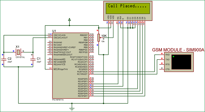
如您所见,我们在Proteus中使用了虚拟终端选项来检查程序是否按预期响应。我们可以通过弹出对话框输入值。例如,一旦我们点击运行,就会出现一个像上面这样的黑色对话框并显示 AT,这意味着它已将 GSM 模块发送到 AT,现在我们可以通过在框中输入“确定”并按回车键来回复 PIC,PIC 将响应它。同样,我们可以尝试所有 AT 命令。

使用 GSM 和 PIC 拨打和接听电话:

了解代码和硬件的工作原理后,只需将以下程序上传到 PIC 并打开模块电源即可。如果一切正常,您的液晶屏应显示“检测到模块”,“检测到SIM卡”和“呼叫已放置”。一旦您看到“已拨打电话”,您将接到程序中指定的号码的来电。

您也可以尝试拨打GSM模块中的号码,LCD将显示“来电”以指示正在呼叫SIM卡。

与PIC微控制器接口GSM模块 - 拨打和接听电话

// CONFIG

#pragma config FOSC = HS       // Oscillator Selection bits (HS oscillator)

#pragma config WDTE = OFF       // Watchdog Timer Enable bit (WDT disabled)

#pragma config PWRTE = OFF       // Power-up Timer Enable bit (PWRT enabled)

#pragma config BOREN = OFF        // Brown-out Reset Enable bit (BOR enabled)

#pragma config LVP = OFF        // Low-Voltage (Single-Supply) In-Circuit Serial Programming Enable bit (RB3 is digital I/O, HV on MCLR must be used for programming)

#pragma config CPD = OFF        // Data EEPROM Memory Code Protection bit (Data EEPROM code protection off)

#pragma config WRT = OFF        // Flash Program Memory Write Enable bits (Write protection off; all program memory may be written to by EECON control)

#pragma config CP = OFF         // Flash Program Memory Code Protection bit (Code protection off)

//End of CONFIG registers


#define _XTAL_FREQ 20000000

#define RS RD2

#define EN RD3

#define D4 RD4

#define D5 RD5

#define D6 RD6

#define D7 RD7


#define SIM900_OK 1

#define SIM900_READY 2

#define SIM900_FAIL 3

#define SIM900_RING 4

#define SIM900_NC 5

#define SIM900_UNLINK 6


#include


// Wait for any response on the input

inline unsigned char _SIM900_waitResponse(void);

    int recv;

    char p =1;


//LCD Functions Developed by Circuit Digest.

void Lcd_SetBit(char data_bit) //Based on the Hex value Set the Bits of the Data Lines

{

if(data_bit& 1) 

D4 = 1;

else

D4 = 0;


if(data_bit& 2)

D5 = 1;

else

D5 = 0;


if(data_bit& 4)

D6 = 1;

else

D6 = 0;


if(data_bit& 8) 

D7 = 1;

else

D7 = 0;

}


void Lcd_Cmd(char a)

{

RS = 0;           

Lcd_SetBit(a); //Incoming Hex value

EN  = 1;         

        __delay_ms(4);

        EN  = 0;         

}


void Lcd_Clear()

{

Lcd_Cmd(0); //Clear the LCD

Lcd_Cmd(1); //Move the curser to first position

}


void Lcd_Set_Cursor(char a, char b)

{

char temp,z,y;

if(a== 1)

{

 temp = 0x80 + b - 1; //80H is used to move the curser

z = temp>>4; //Lower 8-bits

y = temp & 0x0F; //Upper 8-bits

Lcd_Cmd(z); //Set Row

Lcd_Cmd(y); //Set Column

}

else if(a== 2)

{

temp = 0xC0 + b - 1;

z = temp>>4; //Lower 8-bits

y = temp & 0x0F; //Upper 8-bits

Lcd_Cmd(z); //Set Row

Lcd_Cmd(y); //Set Column

}

}


void Lcd_Start()

{

  Lcd_SetBit(0x00);

  for(int i=1065244; i<=0; i--)  NOP();  

  Lcd_Cmd(0x03);

__delay_ms(5);

  Lcd_Cmd(0x03);

__delay_ms(11);

  Lcd_Cmd(0x03); 

  Lcd_Cmd(0x02); //02H is used for Return home -> Clears the RAM and initializes the LCD

  Lcd_Cmd(0x02); //02H is used for Return home -> Clears the RAM and initializes the LCD

  Lcd_Cmd(0x08); //Select Row 1

  Lcd_Cmd(0x00); //Clear Row 1 Display

  Lcd_Cmd(0x0C); //Select Row 2

  Lcd_Cmd(0x00); //Clear Row 2 Display

  Lcd_Cmd(0x06);

}


void Lcd_Print_Char(char data)  //Send 8-bits through 4-bit mode

{

   char Lower_Nibble,Upper_Nibble;

   Lower_Nibble = data&0x0F;

   Upper_Nibble = data&0xF0;

   RS = 1;             // => RS = 1

   Lcd_SetBit(Upper_Nibble>>4);             //Send upper half by shifting by 4

   EN = 1;

   for(int i=2130483; i<=0; i--)  NOP(); 

   EN = 0;

   Lcd_SetBit(Lower_Nibble); //Send Lower half

   EN = 1;

   for(int i=2130483; i<=0; i--)  NOP();

   EN = 0;

}


void Lcd_Print_String(char *a)

{

int i;

for(i=0;a[i]!='\\0';i++)

  Lcd_Print_Char(a[i]);  //Split the string using pointers and call the Char function 

}

/*****End of LCD Functions*****/


//***Initialize UART for SIM900**//

void Initialize_SIM900(void)

{

    //****Setting I/O pins for UART****//

    TRISC6 = 0; // TX Pin set as output

    TRISC7 = 1; // RX Pin set as input

    //________I/O pins set __________//


    /**Initialize SPBRG register for required 

    baud rate and set BRGH for fast baud_rate**/

    SPBRG = 129; //SIM900 operates at 9600 Baud rate so 129

    BRGH  = 1;  // for high baud_rate

    //_________End of baud_rate setting_________//


    //****Enable Asynchronous serial port*******//

    SYNC  = 0;    // Asynchronous

    SPEN  = 1;    // Enable serial port pins

    //_____Asynchronous serial port enabled_______//

    //**Lets prepare for transmission & reception**//

    TXEN  = 1;    // enable transmission

    CREN  = 1;    // enable reception

    //__UART module up and ready for transmission and reception__//


    //**Select 8-bit mode**//  

    TX9   = 0;    // 8-bit reception selected

    RX9   = 0;    // 8-bit reception mode selected

    //__8-bit mode selected__//     

}

//________UART module Initialized__________//


//**Function to send one byte of date to UART**//

void _SIM900_putch(char bt)  

{

    while(!TXIF);  // hold the program till TX buffer is free

    TXREG = bt; //Load the transmitter buffer with the received value

}

//_____________End of function________________//


//**Function to get one byte of date from UART**//

char _SIM900_getch()   

{

    if(OERR) // check for Error 

    {

        CREN = 0; //If error -> Reset 

        CREN = 1; //If error -> Reset 

    }


    while(!RCIF);  // hold the program till RX buffer is free


    return RCREG; //receive the value and send it to main function

}

//_____________End of function________________//


//**Function to convert string to byte**//

void SIM900_send_string(char* st_pt)

{

    while(*st_pt) //if there is a char

        _SIM900_putch(*st_pt++); //process it as a byte data

}

//___________End of function______________//

//**End of modified Codes**//


void _SIM900_print(unsigned const char *ptr) {

    while (*ptr != 0) {

        _SIM900_putch(*ptr++);

    }

}


bit SIM900_isStarted(void) {

    _SIM900_print("AT\\r\\n");

    return (_SIM900_waitResponse() == SIM900_OK);

}


bit SIM900_isReady(void) {

    _SIM900_print("AT+CPIN?\\r\\n");

    return (_SIM900_waitResponse() == SIM900_READY);

}


inline unsigned char _SIM900_waitResponse(void) {

    unsigned char so_far[6] = {0,0,0,0,0,0};

    unsigned const char lengths[6] = {2,12,5,4,6,6};

    unsigned const char* strings[6] = {"OK", "+CPIN: READY", "ERROR", "RING", "NO CARRIER", "Unlink"};

    unsigned const char responses[6] = {SIM900_OK, SIM900_READY, SIM900_FAIL, SIM900_RING, SIM900_NC, SIM900_UNLINK};

    unsigned char received;

    unsigned char response;

    char continue_loop = 1;

    while (continue_loop) {

        received = _SIM900_getch();

        for (unsigned char i = 0; i < 6; i++) {

            if (strings[i][so_far[i]] == received) {

                so_far[i]++;

                if (so_far[i] == lengths[i]) {

                    response = responses[i];

                    continue_loop = 0;

                }

            } else {

                so_far[i] = 0;

            }

        }

    }

    return response;

}


void main(void)

{   

    //I/O Declarations//

    TRISD = 0x00;  //LCD pins on port D as output

    //End of I/O declaration//


    Lcd_Start();   //Initialize LCD 

    Initialize_SIM900();//lets get our Serial ready for action


    Lcd_Set_Cursor(1,1);

    Lcd_Print_String("SIM900 & PIC");


       /*Check if the SIM900 communication is successful*/

    do

    {

    Lcd_Set_Cursor(2,1);

    Lcd_Print_String("Module not found");

    }while (!SIM900_isStarted()); //wait till the GSM to send back "OK"

    Lcd_Set_Cursor(2,1);

    Lcd_Print_String("Module Detected ");

    __delay_ms(1500);


       /*Check if the SIM card is detected*/

     do

    {

    Lcd_Set_Cursor(2,1);

    Lcd_Print_String("SIM not found   ");

    }while (!SIM900_isReady()); //wait till the GSM to send back "+CPIN: READY"

    Lcd_Set_Cursor(2,1);

    Lcd_Print_String("SIM Detected    ");

    __delay_ms(1500);


   Lcd_Clear();


     /*Place a Phone Call*/

     do

    {

    _SIM900_print("ATD93643XXXXX;\\r\\n");  //Here we are placing a call to number 93643XXXXX

    Lcd_Set_Cursor(1,1);

    Lcd_Print_String("Placing Call....");

    }while (_SIM900_waitResponse() != SIM900_OK); //wait till the ESP send back "OK"

    Lcd_Set_Cursor(1,1);

    Lcd_Print_String("Call Placed....");

    __delay_ms(1500);


    while(1)

    {

        if (_SIM900_waitResponse() == SIM900_RING) //Check if there is an incoming call

        {

          Lcd_Set_Cursor(2,1);

          Lcd_Print_String("Incoming Call!!.");  

        }       

    }

}
声明:本文内容及配图由入驻作者撰写或者入驻合作网站授权转载。文章观点仅代表作者本人,不代表电子发烧友网立场。文章及其配图仅供工程师学习之用,如有内容侵权或者其他违规问题,请联系本站处理。 举报投诉
  • 微控制器
    +关注

    关注

    48

    文章

    6830

    浏览量

    147836
  • PIC
    PIC
    +关注

    关注

    8

    文章

    507

    浏览量

    86813
  • GSM模块
    +关注

    关注

    6

    文章

    48

    浏览量

    22981
收藏 人收藏

    评论

    相关推荐

    GSM模块的,SIM900A原子的模块,打电话发短信,GPRS

    有没有需要GSM模块的哈,SIM900A原子的模块,全新未拆封,买了两块,只用了一块,所以把另外一块卖掉,想再玩玩其它模块,希望网友支持,可
    发表于 12-29 22:34

    SIM900A短信模块

    求大神给个SIM900A接听指定电话的程序,只需要能够判断是不是指定来电即可,万分感谢
    发表于 07-16 16:56

    sim900a模块说明图中是指stm32连接GSM模块GSM模块通过串口线和电脑连接吗?

    sim900a模块说明里这个地方是stm32连接GSM模块GSM
    发表于 03-08 04:25

    STM32 GSM电话SIM900A模块命令手册

    最近买了一块GSMSIM900A)的板子,回来后用三根线连接MiniSTM32开发板和SIM900A板子实现3线串口通信,调试了一个比较简
    发表于 05-08 12:24

    请问有SIM900A简易代码吗?

    SIM900A简易程序,能够实现拨打电话和发短息的
    发表于 05-21 02:01

    基于SIM900A的应用与实现

    本文对GSM、GPRS系统做了简要介绍,讲解了GSM、GPRS系统的相关组成与功能。并选用SIM900A模块设计了一个硬件电路系统,该模块
    发表于 08-05 06:16

    单片机控制SIM900AGSM模块发送数字短信(附源码)精选资料分享

    一、模块概述SIM900A是由SIMCom推出的新款紧凑型产品,它属于双频GSM/GPRS模块,完全采用SMT封装形式,SIM900A仅适用
    发表于 07-21 08:06

    怎样电动机控制利用模块连接起来

    利用 Matlab 中 Simulink 的可视化仿真工具,电动机控制利用模块连接起来,构成复杂的系统模型,并进行仿真和分析[1]。本文
    发表于 09-06 07:48

    怎么才能使Atmel Studio 7.0伺服电机与Atmega16 AVR微控制器连接起来

    怎么才能使Atmel Studio 7.0伺服电机与Atmega16 AVR微控制器连接起来
    发表于 09-29 08:37

    如何蓝牙与STM32连接起来

    蓝牙模块有何功能?如何蓝牙与STM32连接起来呢?
    发表于 11-18 07:02

    如何HLW8032与NodeMCU连接起来

    我正在尝试 HLW8032 与 NodeMCU 连接起来。我示例中的代码上传到微控制器,但我在串行监视上获取垃圾值。 当我尝试获取有关
    发表于 05-10 12:59

    sim900a模块简介_sim900a原理图

    本文首先介绍了SIM900A模块主要特点与功能,其次介绍了sim900a功能框图与原理图,最后介绍了sim900a模块引脚及功能。
    的头像 发表于 05-30 14:50 15.2w次阅读
    <b class='flag-5'>sim900a</b><b class='flag-5'>模块</b>简介_<b class='flag-5'>sim900a</b>原理图

    GSM和GPRS的原理与应用详解及SIM900A使设计一个双频GSM和GPRS模块

    本文对GSM、GPRS系统做了简要介绍,讲解了GSM、GPRS系统的相关组成与功能。并选用SIM900A模块设计了一个硬件电路系统,该模块
    发表于 05-30 17:55 23次下载
    <b class='flag-5'>GSM</b>和GPRS的原理与应用详解及<b class='flag-5'>SIM900A</b>使设计一个双频<b class='flag-5'>GSM</b>和GPRS<b class='flag-5'>模块</b>

    使用Arduino实现GSM模块SIM900A电话的实验免费下载

    本文档的主要内容详细介绍的是使用Arduino实现GSM模块SIM900A电话的实验免费下载。
    发表于 03-12 15:24 32次下载

    单片机控制SIM900AGSM模块发送数字短信(附源码)

    一、模块概述SIM900A是由SIMCom推出的新款紧凑型产品,它属于双频GSM/GPRS模块,完全采用SMT封装形式,SIM900A仅适用
    发表于 11-23 17:36 92次下载
    单片机<b class='flag-5'>控制</b><b class='flag-5'>SIM900A</b>型<b class='flag-5'>GSM</b><b class='flag-5'>模块</b>发送数字短信(附源码)