 如何将GPS模块与PIC微控制器连接以获取当前位置的纬度和经度

GPS是全球定位系统的简称。它是一个提供准确的高度,纬度,经度,UTC时间和更多信息的系统,这些信息来自2,3,4或更多卫星。要从GPS读取数据,我们需要一些微控制器,我们已经将GPS与Arduino和Raspberry Pi连接在一起。
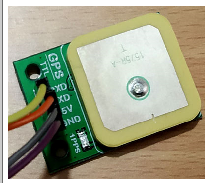
我们选择了由U-blox制造的G7020 GPS模块。我们将从卫星接收特定位置的经度和纬度,并将在 16x2 字符 LCD 上显示相同的经度和纬度。因此,在这里我们将通过微芯片将GPS与PIC16F877A微控制器连接。
所需组件:
Pic16F877A – PDIP40 封装
面包板
皮基特-3
5V 适配器
液晶显示器 JHD162A
uBLOX-G7020 全球定位系统模块
用于连接外围设备的电线。
4.7k 电阻器
10k锅
20mHz 晶体
2 个 33pF 陶瓷电容器
电路图和说明:-
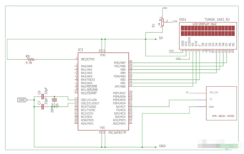
16x2字符LCD通过PIC16F877A微控制器连接,其中RB0,RB1,RB2分别连接到LCD引脚RS,R / W和E.RB4,RB5,RB6和RB7通过LCD的4针D4,D5,D6,D7连接。液晶屏以4位模式或半字节模式连接。
一个 20MHz 的晶体振荡器,带有两个 33pF 的陶瓷电容器,连接在 OSC1 和 OSC2 引脚上。它将为微控制器提供恒定的20 MHz时钟频率。
uBlox-G7020 GPS模块,使用UART接收和传输数据。PIC16F877A由芯片内部的一个USART驱动器组成,我们将通过USART从GPS模块接收数据,因此将从微控制器Rx引脚到GPS的Tx引脚和USART接收引脚通过GPS的传输引脚连接进行交叉连接。
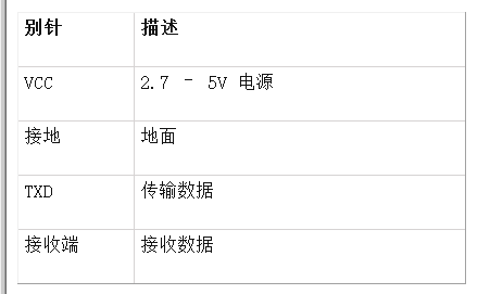
uBlox-G7020 具有引脚的颜色代码。正极或5V引脚为红色,负极或GND引脚为黑色,传输引脚为蓝色。
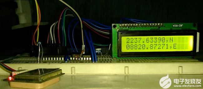
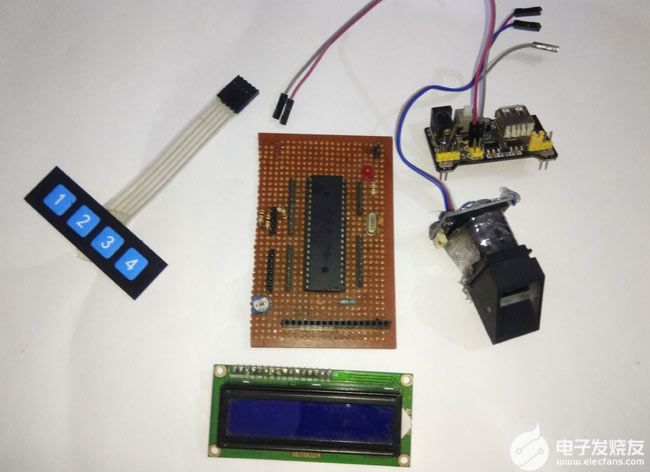
我已经在面包板上连接了所有这些。
从 GPS 获取位置数据:
让我们看看如何使用 USART 连接 GPS,并在 16x2 字符 LCD 中查看结果。
该模块将以 9600 波特率在多个字符串中传输数据。如果我们使用波特率为9600的UART终端,我们将看到GPS接收的数据。
GPS模块以NMEA格式发送实时跟踪位置数据(请参见上面的屏幕截图)。NMEA格式由几个句子组成,其中四个重要句子如下。
这是GPS在9600波特率连接时接收的数据。
$GPRMC,141848.00,A,2237.63306,N,08820.86316,E,0.553,,100418,,,A*73
$GPVTG,,T,,M,0.553,N,1.024,K,A*27
$GPGGA,141848.00,2237.63306,N,08820.86316,E,1,03,2.56,1.9,M,-54.2,M,,*74
$GPGSA,A,2,06,02,05,,,,,,,,,,2.75,2.56,1.00*02
$GPGSV,1,1,04,02,59,316,30,05,43,188,25,06,44,022,23,25,03,324,*76
$GPGLL,2237.63306,N,08820.86316,E,141848.00,A,A*65
当我们使用GPS模块跟踪任何位置时,我们只需要坐标,我们可以在字符串中找到$GPGGA。只有$GPGGA(全球定位系统修复数据)字符串主要用于程序,其他字符串被忽略。
$GPGGA,141848.00,2237.63306,N,08820.86316,E,1,03,2.56,1.9,M,-54.2,M,,*74
这句话是什么意思?
该行的含义是:-
1. 字符串始终以“$”符号开头
2. GPGGA 代表 全球定位系统定位数据
3. “,”逗号表示两个值之间的分隔
4. 141848.00:格林威治标准时间为 14(小时):18(分钟):48(秒):00(毫秒)
5. 2237.63306,N:北纬22度(度)37(分)63306(秒)北纬
6. 08820.86316,E:东经088(度)20(分)86316(秒)
7. 1:修复数量0=无效数据,1=有效数据,2=DGPS修复
8. 03 : 当前查看的卫星数量。
9. 1.0: HDOP
10. 2.56,米:海拔高度(海拔高度,单位:米)
11. 1.9,M : 大地水准面高度
12. *74 : 校验和
因此,我们需要 5 号和 6 号来收集有关模块位置或模块位置的信息。
将GPS与PIC微控制器连接的步骤:-
设置微控制器的配置,包括振荡器配置。
使用 USART 将 GPS 模块连接到微控制器。
在连续接收模式下初始化系统 USART,波特率为 9600,LCD 具有 4 位模式。
根据纬度和经度的长度采用两个字符数组。
一次接收一个字符位,并检查它是否从 $ 开始。
如果 $ 接收,那么它是一个字符串,我们需要检查 GPGGA、这 5 个字母和逗号。
如果是 GPGGA,那么我们将跳过时间,并寻找纬度和经度,我们将纬度和经度存储在两个字符数组中,直到 N(北)和 E(东)未收到。
我们将在LCD中打印阵列。
清除阵列。
代码说明:
让我们逐行查看代码。前几行用于设置配置位,这些配置位在上一个教程中已经解释过,所以我现在跳过它们。本教程末尾给出了完整的代码。
这五行用于包括库头文件,lcd.h 和 eusart.h 分别用于 LCD 和 USART。xc.h 用于微控制器头文件。
#include
#include
#include
#include "supporing_cfilelcd.h"
#include "supporing_cfileeusart1.h"
在 void main() 函数中,system_init();函数用于初始化LCD和USART。
Void main(void) {
TRISB = 0x00; // Setting as output
system_init();
lcd_init(); 和 EUSART_Intialize(); 从两个库 lcd.h 和 eusart.h 调用
void system_init(void){
lcd_init(); // This will initialise the lcd
EUSART1_Initialize(); // This will initialise the Eusart
}
在 while 循环中,我们中断 GPGGA 字符串以获取经度和纬度坐标。我们一次接收一位,并将其与 GPGGA 字符串中存在的单个字符进行比较。
我们打破了我们将得到的代码:-
incomer_data=EUSART1_Read(); // Check the string '$GPGGA,'
/*------------------------------ Step by step finding the GPGGA line----------------------------*/
if(incomer_data=='$'){ // First statement of the GPS data start with a $ sign
incomer_data=EUSART1_Read(); // If the first if become true then the next phase
if(incomer_data=='G'){
incomer_data=EUSART1_Read();
if(incomer_data=='P');{
incomer_data=EUSART1_Read();
if(incomer_data=='G');{
incomer_data=EUSART1_Read();
if(incomer_data=='G'){
incomer_data=EUSART1_Read();
if(incomer_data=='A'){
incomer_data=EUSART1_Read();
if(incomer_data==','){ // first , received
incomer_data=EUSART1_Read(); // At this stage Final check in done, GPGGA is found.
通过使用此代码,我们跳过了 UTC 时间。
while (incomer_data != ','){ // skipping GMT Time
incomer_data=EUSART1_Read();
}
此代码用于将纬度和经度数据存储在字符数组中。
incomer_data=EUSART1_Read();
latitude[0] = incomer_data;
while(incomer_data != ','){
for(array_count=1;incomer_data!='N';array_count++){
incomer_data=EUSART1_Read();
latitude[array_count]=incomer_data; // Store the Latitude data
}
incomer_data=EUSART1_Read();
if(incomer_data==','){
for(array_count=0;incomer_data!='E';array_count++){
incomer_data=EUSART1_Read();
longitude[array_count]=incomer_data; // Store the Longitude data
}
}
最后,我们在LCD上打印了经度和纬度。
array_count=0;
lcd_com(0x80); // LCD line one selection
while(array_count<12){ // Array of Latitude data is 11 digit
lcd_data(latitude[array_count]); // Print the Latitude data
array_count++;
}
array_count=0;
lcd_com(0xC0); // Lcd line two selection
while(array_count<13){ // Array of Longitude data is 12 digit
lcd_data(longitude[array_count]); // Print the Longitude data
array_count++;
}
这就是我们如何将GPS模块与PIC微控制器连接以获取当前位置的纬度和经度。
/*
* File: main.c
* Author: Sourav Gupta
* By:- circuitdigest.com
* Created on April 1, 2018, 2:26 PM
*/
// PIC16F877A Configuration Bit Settings
// 'C' source line config statements
// CONFIG
#pragma config FOSC = HS // Oscillator Selection bits (HS oscillator)
#pragma config WDTE = OFF // Watchdog Timer Enable bit (WDT disabled)
#pragma config PWRTE = OFF // Power-up Timer Enable bit (PWRT disabled)
#pragma config BOREN = ON // Brown-out Reset Enable bit (BOR enabled)
#pragma config LVP = OFF // Low-Voltage (Single-Supply) In-Circuit Serial Programming Enable bit (RB3/PGM pin has PGM function; low-voltage programming enabled)
#pragma config CPD = OFF // Data EEPROM Memory Code Protection bit (Data EEPROM code protection off)
#pragma config WRT = OFF // Flash Program Memory Write Enable bits (Write protection off; all program memory may be written to by EECON control)
#pragma config CP = OFF // Flash Program Memory Code Protection bit (Code protection off)
#include
#include
#include
#include "supporing_cfilelcd.h"
#include "supporing_cfileeusart1.h"
/*
Hardware related definition
*/
#define _XTAL_FREQ 200000000 //Crystal Frequency, used in delay
/*
Other Specific definition
*/
void system_init(void);
unsigned char incomer_data = 0;
unsigned char longitude[13];
unsigned char latitude[13];
unsigned int array_count=0;
/* Sample line received from the GPS :-
[$GPGGA,100156.000,2690.9416,N,07547.8441,E,1,08,1.0,442.8,M,-42.5,M,,0000*71]
1. string always starts with a ?$? sign
2. GPGGA : Global Positioning System Fix Data
3. ?,? Comma indicates the separation between two values
4. 100156.000 : GMT time as 10(hr):01(min):56(sec):000(ms)
5. 2650.9416,N: Latitude 26(degree) 50(minutes) 9416(sec) North
6. 07547.8441,E: Longitude 075(degree) 47(minutes) 8441(sec) East
7. 1 : Fix Quantity 0= invalid data, 1= valid data, 2=DGPS fix
8. 08 : Number of satellites currently viewed.
9. 1.0: HDOP
10. 442.8,M : Altitude (Height above sea level in meter)
11. -42.5,M : Geoids height
12. __ , DGPS data
13. 0000 : DGPS data
14. *71 : checksum
*/
void main(void) {
TRISB = 0x00; // Setting as output
system_init(); // System getting ready and initialising the LCD and USART driver.
//LCD_ScrollMessage("Circuitdigest.com");
while(1){
incomer_data=EUSART1_Read(); // Check the string '$GPGGA,'
/*------------------------------ Step by step finding the GPGGA line----------------------------*/
if(incomer_data=='$'){ // First statement of the GPS data start with a $ sign
incomer_data=EUSART1_Read(); // If the first if become true then the next phase
if(incomer_data=='G'){
incomer_data=EUSART1_Read();
if(incomer_data=='P');{
incomer_data=EUSART1_Read();
if(incomer_data=='G');{
incomer_data=EUSART1_Read();
if(incomer_data=='G'){
incomer_data=EUSART1_Read();
if(incomer_data=='A'){
incomer_data=EUSART1_Read();
if(incomer_data==','){ // first , received
incomer_data=EUSART1_Read(); // At this stage Final check in done, GPGGA is found.
while (incomer_data != ','){ // skipping GMT Time
incomer_data=EUSART1_Read();
}
incomer_data=EUSART1_Read();
latitude[0] = incomer_data;
while(incomer_data != ','){
for(array_count=1;incomer_data!='N';array_count++){
incomer_data=EUSART1_Read();
latitude[array_count]=incomer_data; // Store the Latitude data
}
incomer_data=EUSART1_Read();
if(incomer_data==','){
for(array_count=0;incomer_data!='E';array_count++){
incomer_data=EUSART1_Read();
longitude[array_count]=incomer_data; // Store the Longitude data
}
}
array_count=0;
//lcd_com(0x80); // LCD line one selection
while(array_count<12){ // Array of Latitude data is 11 digit
lcd_data(latitude[array_count]); // Print the Latitude data
array_count++;
}
array_count=0;
lcd_com(0xC0); // Lcd line two selection
while(array_count<13){ // Array of Longitude data is 12 digit
lcd_data(longitude[array_count]); // Print the Longitude data
array_count++;
}
//lcd_com(0x01); //clear LCD
}
}
}
}
}
}
}
}
for(array_count=0;array_count<=13;array_count++){
incomer_data=0;
latitude[array_count]=0;
longitude[array_count]=0;
}
array_count = 0;
}
}
/*
This Function is for system initialisations.
*/
void system_init(void){
lcd_init(); // This will initialise the lcd
EUSART1_Initialize(); // This will initialise the Eusart
}
-
微控制器
+关注
关注
49文章
8909浏览量
166036 -
gps
+关注
关注
22文章
3061浏览量
174330 -
PIC16F877A
+关注
关注
2文章
43浏览量
22440
发布评论请先 登录
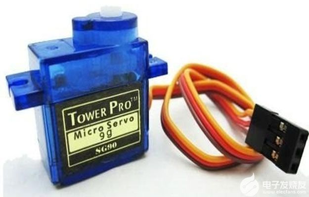
将伺服电机与PIC微控制器连接的教程
如何将超声波传感器HC-SR04与PIC微控制器连接
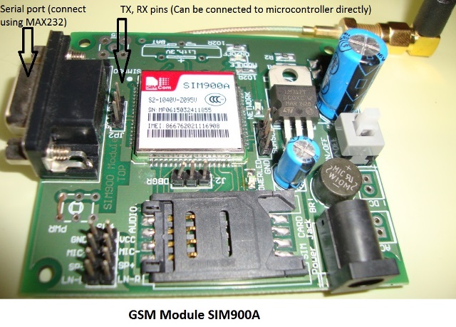
将SIM900A与PIC微控制器连接起来实现GSM模块拨打和接听电话
如何处理51单片机从GPS数据中读取的数据得到经度和纬度坐标
如何将伺服电动机与PIC微控制器连接

GPS模块与ATmega16接口查找位置坐标的方式

如何将指纹传感器与PIC微控制器连接


评论