 计算机屏幕锁定的安全性

步骤1:组件
因为概念证明,我们将在面包板上构建设备
您需要:
1。 Arduino Leonardo(使用Leonardo非常重要,因为它可以模拟键盘rd)
2。。HC-SR04超声波距离传感器
3。 2个10 K可变电阻器
4。面包板,面包板电线
5。 USB电缆
6。 OLED显示屏(https://www.adafruit.com/product/931)
步骤2:组装和上传
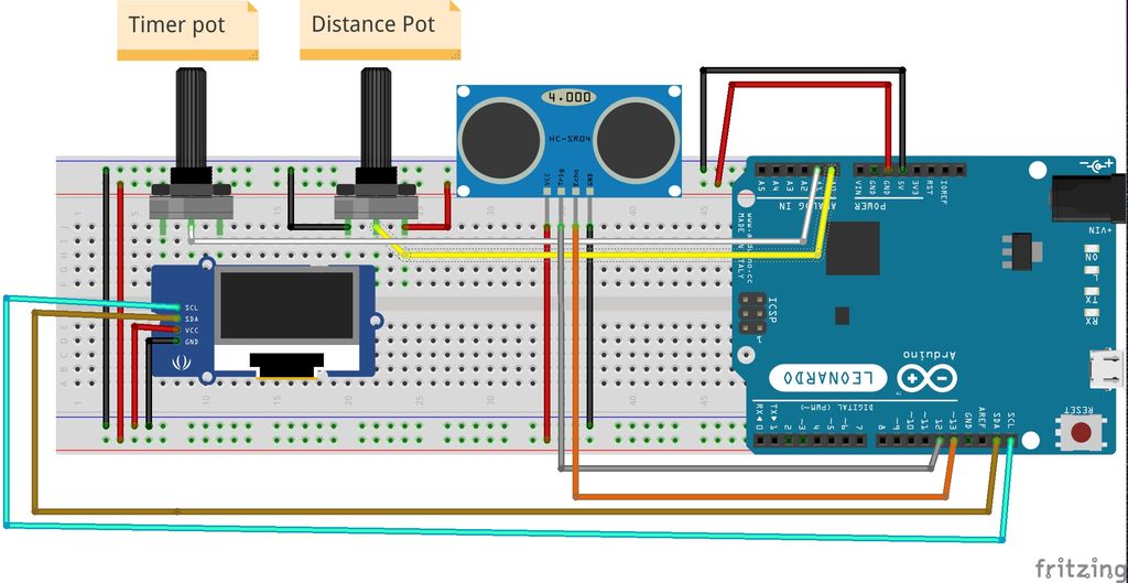
首先检查您是否具有所有必需的组件和Arduino IDE。我将简要地介绍连接步骤,您随时可以查看所附的压条示意图
装配
1。将Leonardo放在面包板上,并用橡皮筋将其固定到位
2。在面包板上放置两个可变电阻OLED显示器和超声波传感器
3。连接接地和vcc的
4。将电阻的中间引脚连接到arduino A0和A1
5。将显示器的SDA和SCL连接到列昂纳多(Leonardo)
6上标记的SDA和SCL。将超声波传感器的触发和回波引脚连接到Leonardo
7的12、13个数字引脚。将USB连接到计算机
上传
首先,您需要下载并安装必要的arduino库:
1。 GOFi2cOLED库:https://github.com/hramrach/GOFi2cOLED
2. Ultrasonic-HC-SR04库:https://github.com/JRodrigoTech/Ultrasonic-HC-SR04
如果您不知道如何安装arduino库,请查看本教程。
下载并安装了库之后上方,您可以克隆或下载位于以下位置的arduino存储库:https://github.com/danionescu0/arduino,我们将使用此草图:https://github.com/danionescu0/arduino/tree/master。 。
或者您可以复制并粘贴以下代码:
/*
* Libraries used by this project:
*
* GOFi2cOLED: https://github.com/hramrach/GOFi2cOLED
* Ultrasonic-HC-SR04: https://github.com/JRodrigoTech/Ultrasonic-HC-SR04
*/
#include “Keyboard.h”
#include “Wire.h”
#include “GOFi2cOLED.h”
#include “Ultrasonic.h”
GOFi2cOLED GOFoled;
Ultrasonic ultrasonic(12,13);
const byte distancePot = A0;
const byte timerPot = A1;
const float percentMaxDistanceChangedAllowed = 25;
int actualDistance;
unsigned long maxDistanceDetectionTime;
bool lockTimerStarted = false;
void setup()
{
Serial.begin(9600);
Keyboard.begin();
initializeDisplay();
}
void loop()
{
clearDisplay();
actualDistance = getActualDistance();
writeStatusData();
doDisplay();
if (!lockTimerStarted && shouldEnableLockTimer()) {
lockTimerStarted = true;
maxDistanceDetectionTime = millis();
Serial.println(“lock timer begin”);
} else if (!shouldEnableLockTimer()){
Serial.println(“lock timer disabled”);
lockTimerStarted = false;
}
if (shouldLockScreen()) {
lockScreen();
Serial.println(“Lock screen”);
}
delay(100);
}
bool shouldLockScreen()
{
return lockTimerStarted && (millis() - maxDistanceDetectionTime) / 1000 》 getTimer();
}
bool shouldEnableLockTimer()
{
int allowedDistance = percentMaxDistanceChangedAllowed / 100 * getDistance();
return getTimer() 》 1 && getDistance() 》 1 && actualDistance - getDistance() 》 allowedDistance;
}
void writeStatusData()
{
setDisplayText(1, “MinDistance:”, String(getDistance()));
setDisplayText(1, “Timer:”, String(getTimer()));
setDisplayText(1, “ActualDistance:”, String(actualDistance));
int countDown = getTimer() - (millis() - maxDistanceDetectionTime) / 1000;
String message = “”;
if (shouldLockScreen()) {
message = “lock sent”;
} else if (shouldEnableLockTimer() && countDown 》= 0) {
message = “。.” + String(countDown);
} else {
message = “no”;
}
setDisplayText(1, “Locking: ”, message);
}
void initializeDisplay()
{
GOFoled.init(0x3C);
GOFoled.clearDisplay();
GOFoled.setCursor(0, 0);
}
void setDisplayText(byte fontSize, String label, String data)
{
GOFoled.setTextSize(fontSize);
GOFoled.println(label + “:” + data);
}
void doDisplay()
{
GOFoled.display();
}
void clearDisplay()
{
GOFoled.clearDisplay();
GOFoled.setCursor(0, 0);
}
int getActualDistance()
{
int distanceSum = 0;
for (byte i=0;i《10;i++) {
distanceSum += ultrasonic.Ranging(CM);
}
return distanceSum / 10;
}
int getDistance()
{
return map(analogRead(timerPot), 0, 1024, 0, 200);
}
int getTimer()
{
return map(analogRead(distancePot), 0, 1024, 0, 20);
}
void lockScreen()
{
Serial.println(“pressing”);
Keyboard.press(KEY_LEFT_CTRL);
delay(10);
Keyboard.press(KEY_LEFT_ALT);
delay(10);
Keyboard.write(‘l’);
delay(10);
Keyboard.releaseAll();
}
最后使用usb电缆将arduino连接到计算机,然后将草图上传到arduino。/p》
第3步:使用设备
将arduino连接到计算机后,它将持续监控显示器前部的距离。传感器,并在距离增加时将“锁定”屏幕按键组合发送到计算机。
设备具有一些配置:
1。正常距离,可以使用连接到A0的可变电阻器来配置距离。距离也显示在OLED上。当距离从设置的距离增加25%时,倒计时将开始
2。超时(倒数)。 还可以通过连接到A1的电阻来配置超时(以秒为单位)。超时到期后,将发送锁定命令
3。锁定组合键。设置了默认的锁定键组合以适用于Ubuntu Linux 18(CTRL + ALT + L)。要更改组合,您需要根据操作系统修改草图:
4。超时和距离保护。 因为这是一种模拟键盘的设备,所以最好有一种停用键盘功能的机制。在我的草图中,我选择超时和距离必须大于“ 1”。 (您可以根据需要在代码中进行修改)
找到并更改“ lockScreen()”功能
void lockScreen()
{
Serial.println(“pressing”);
Keyboard.press(KEY_LEFT_CTRL);
delay(10);
Keyboard.press(KEY_LEFT_ALT);
delay(10);
Keyboard.write(‘l’);
delay(10);
Keyboard.releaseAll();
}
有关arduino特殊键的完整列表,在此处检查:https://www.arduino.cc/en/Reference/KeyboardModifi 。..
步骤4:其他方法
在此实现之前我也考虑了其他一些实现:
1。红外温度计(MLX90614 https://www.sparkfun.com/products/10740)。红外温度计是一种通过分析远距离物体发射的红外辐射来测量温度的设备。我周围躺着一个,我想也许我可以检测到计算机正面的温度差异。
我已经将它挂好了,但是温差很小(无论我在前面还是不在)
1-2度,我认为它不太可靠
2。 PIR传感器。(https://www.sparkfun.com/products/13285)这种便宜的传感器被称为“运动传感器”,但它们确实可以检测到红外辐射的变化,因此从理论上讲,当一个人使用时,它可以工作离开计算机后,传感器将检测到该情况。此外,这些传感器还具有超时和灵敏度旋钮。因此,我已经挂接好它并玩了,但是似乎它不是在近距离内制作的(它有一个广角),它发出了各种错误的警报。
3。使用网络摄像头进行人脸检测。这个选项似乎非常有趣,因为我在其他项目(例如https://github.com/danionescu0/robot-camera-platfo 。..和https://github.com/danionescu0/image-processing-pr 。..
这真是小菜一碟!但是有一些缺点:程序运行时不能将笔记本电脑相机用于其他目的,为此需要一些计算机资源。因此,我也放弃了这个想法。
责任编辑:wv
-
计算机
+关注
关注
19文章
7841浏览量
93465
发布评论请先 登录
计算机专业408考研科目
十进制计算机硬件体系结构及“独值”量化逻辑运算革命(一)
龙芯主板让工控计算机拥有安全可信的核心
工控机与普通计算机的核心差异解析

有哪些技术可以提高边缘计算设备的安全性?
【作品合集】赛昉科技VisionFive 2单板计算机开发板测评
工业计算机的重要性

基于飞腾CPU的安全计算机平台研制项目通过试验评审
自动化计算机经过加固后有什么好处?
自动化计算机的功能与用途

工业计算机与商用计算机的区别有哪些

环旭电子助力客户发布高性能自行车计算机
工业计算机如何设计用于冲击和振动


评论