 电子发烧友App


 创作
创作 发文章
发文章 发帖
发帖  提问
提问  发资料
发资料 发视频
发视频资料介绍
描述
随着大流行的持续,硬件不仅难以采购,而且难以安全地协同工作。在智能微型车辆的情况下,可用单元的数量本质上是有限的,我们部署它们的“环境”也是如此,例如赛道或障碍赛。我们如何解决硬件资源稀缺问题?我们将资源数字化!
> 本文最初发布于platis.solutions
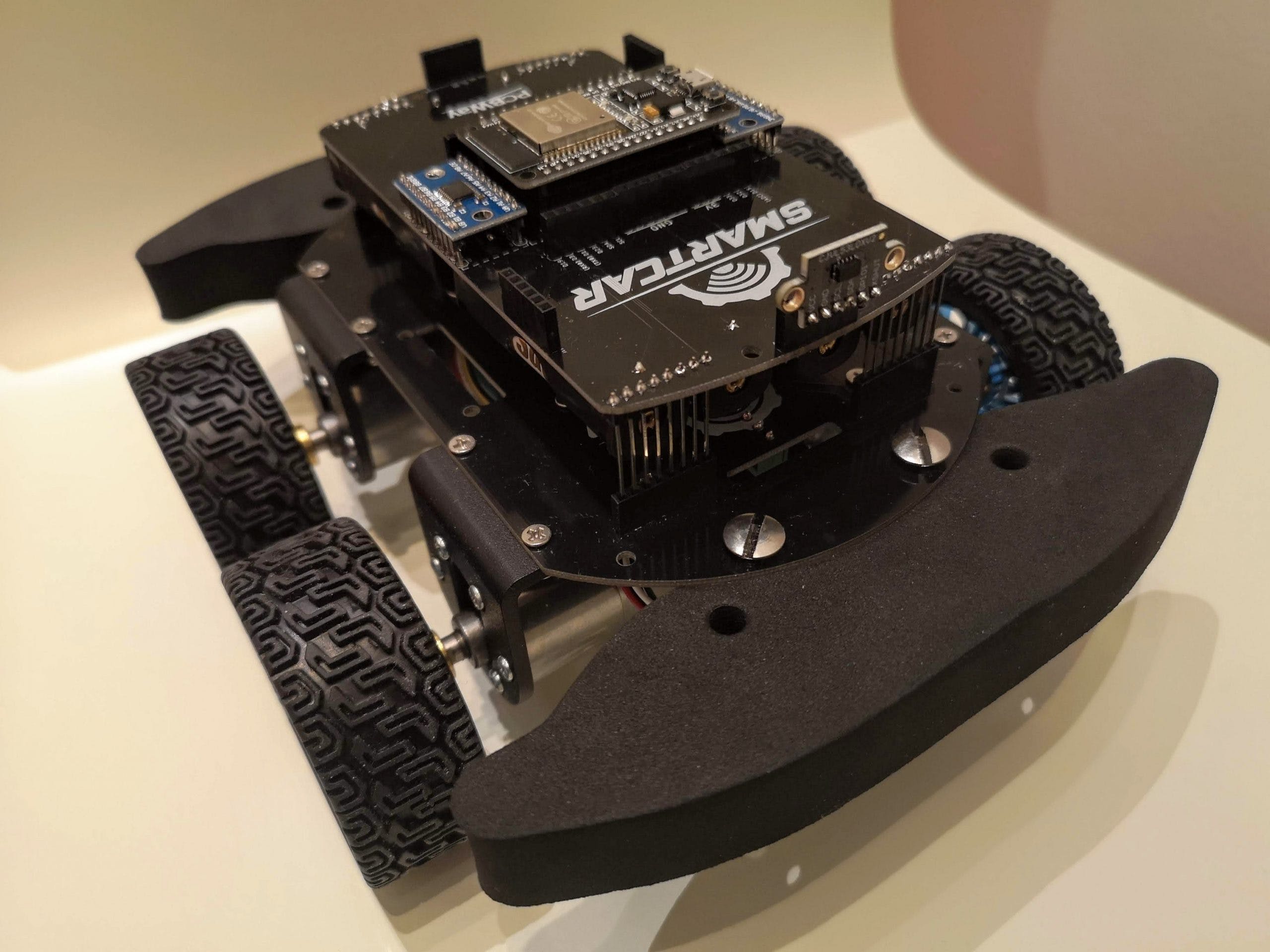
SMCE是Smartcar 平台的数字双胞胎,以及一个酷炫且可定制的3D 世界,供您的漫游车漫游。核心概念是您编写可在两者上运行的 Arduino 代码真实的硬件和虚拟环境。通过这种方式,可以减轻或大大减少对汽车的专有和频繁访问的需求。理想情况下,模拟器允许限制与物理汽车的不可避免的接触,以至于开发团队可以在模拟器上开发他们的功能,并且只访问真实的硬件来验证它们。使用网络物理系统的虚拟表示不仅在大流行期间很有价值。我们这些使用嵌入式系统的人可能会痛苦地认识到由于缺乏硬件可用性而被阻止的不利影响。在这篇文章中,我将向您展示如何开始使用SMCE以及它的许多功能。如果你想要一些关于什么的灵感您可以使用该软件查看我们的学生如何利用SMCE 来模拟 Arduino 车辆。
关于 SMCE
在深入了解模拟器之前,让我们澄清一下 SMCE 不是什么:一个 3D 环境,用于您的超级自定义爱好项目,它使用各种奇异的传感器和第三方库。开箱即用的模拟器可支持Smartcar 库的用户并适应他们的典型用例和传感器设置。模拟器不仅适用于特定的库,但是,如果您使用它,您的生活会轻松得多。我并不是因为模拟器而这么说。它带有很多例子,它用途广泛,总体上是一个非常容易使用的库,您应该尝试一下!此外,我应该注意,模拟器不是由我制作或维护的,所以请不要联系我寻求支持。它是由我的两个非常有才华的前学生Ryan Janson和Ruthger Dijt 开发的。您可以通过在相关 GitHub 存储库之一上创建问题或开始讨论来联系他们。
SMCE 由两部分组成:“前端”(smce-gd)和“后端”(libSMCE)。libSMCE是负责在您的计算机上编译和运行 Arduino 草图的库。
这个跨平台的 C++ 库为其消费者提供了在托管环境中编译和执行 Arduino 草图的能力,并绑定到其虚拟 I/O 端口以允许主机应用程序与其子草图进行交互。
这个跨平台的 C++ 库为其消费者提供了在托管环境中编译和执行 Arduino 草图的能力,并绑定到其虚拟 I/O 端口以允许主机应用程序与其子草图进行交互。
smce-gd取决于在libSMCE多彩的虚拟 3D 世界中可视化草图执行以及与周围环境的交互。除非您打算做一些“聪明”的事情,扩展或为项目做出贡献等,否则smce-gd您应该主要关心的软件。对于本教程,我将使用1.3.1版本,smce-gd在 Ubuntu 20.04 上运行。
开始使用
为了在我的 Ubuntu 笔记本电脑上安装 SMCE,我按照Wiki上的这些说明进行操作。SMCE 的一个非常酷的地方是它可以在您的计算机上运行。SMCE 也可以安装在Windows或MacOS 上。如果 SMCE 安装正确,您将看到以下屏幕:smce-gd
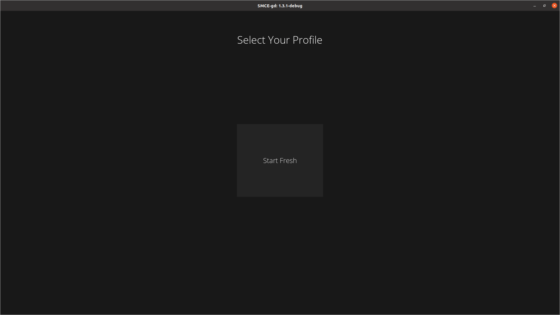
选择Start Fresh选项,然后在下一个屏幕中单击+标志。
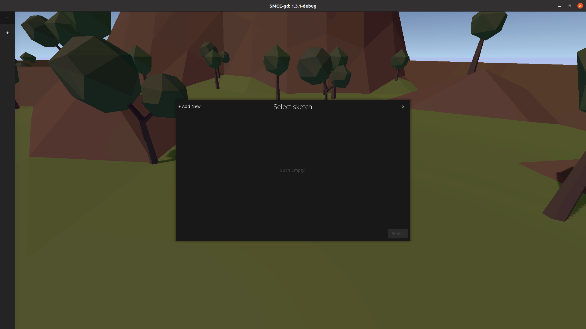
然后是时候选择在 Arduino 上运行的代码了。我建议从Smartcar 库示例中的manualControl.ino草图开始。获取示例的一种简单方法是Smartcar shield通过 Arduino IDE 的库管理器下载库,然后在您的光盘上找到它。让我们看一下草图:
#include

const int fSpeed   = 70;  // 70% of the full speed forward
const int bSpeed   = -70; // 70% of the full speed backward
const int lDegrees = -75; // degrees to turn left
const int rDegrees = 75;  // degrees to turn right

ArduinoRuntime arduinoRuntime;
BrushedMotor leftMotor(arduinoRuntime, smartcarlib::pins::v2::leftMotorPins);
BrushedMotor rightMotor(arduinoRuntime, smartcarlib::pins::v2::rightMotorPins);
DifferentialControl control(leftMotor, rightMotor);

SimpleCar car(control);

void setup()
{
    Serial.begin(9600);
}

void loop()
{
    handleInput();
}

void handleInput()
{ // handle serial input if there is any
    if (Serial.available())
    {
        char input = Serial.read(); // read everything that has been received so far and log down
                                    // the last entry
        switch (input)
        {
        case 'l': // rotate counter-clockwise going forward
            car.setSpeed(fSpeed);
            car.setAngle(lDegrees);
            break;
        case 'r': // turn clock-wise
            car.setSpeed(fSpeed);
            car.setAngle(rDegrees);
            break;
        case 'f': // go ahead
            car.setSpeed(fSpeed);
            car.setAngle(0);
            break;
        case 'b': // go back
            car.setSpeed(bSpeed);
            car.setAngle(0);
            break;
        default: // if you receive something that you don't know, just stop
            car.setSpeed(0);
            car.setAngle(0);
        }
    }
}
上述示例指示流动站(即SimpleCar实例)遵循从串行端口发送的简单命令。具体来说,当f发送时,汽车将以预定义的速度前进,当b发送时,它将向后行驶,r它会向右和l向左转弯。任何其他角色都会停下车。选择草图后,单击“编译”选项。
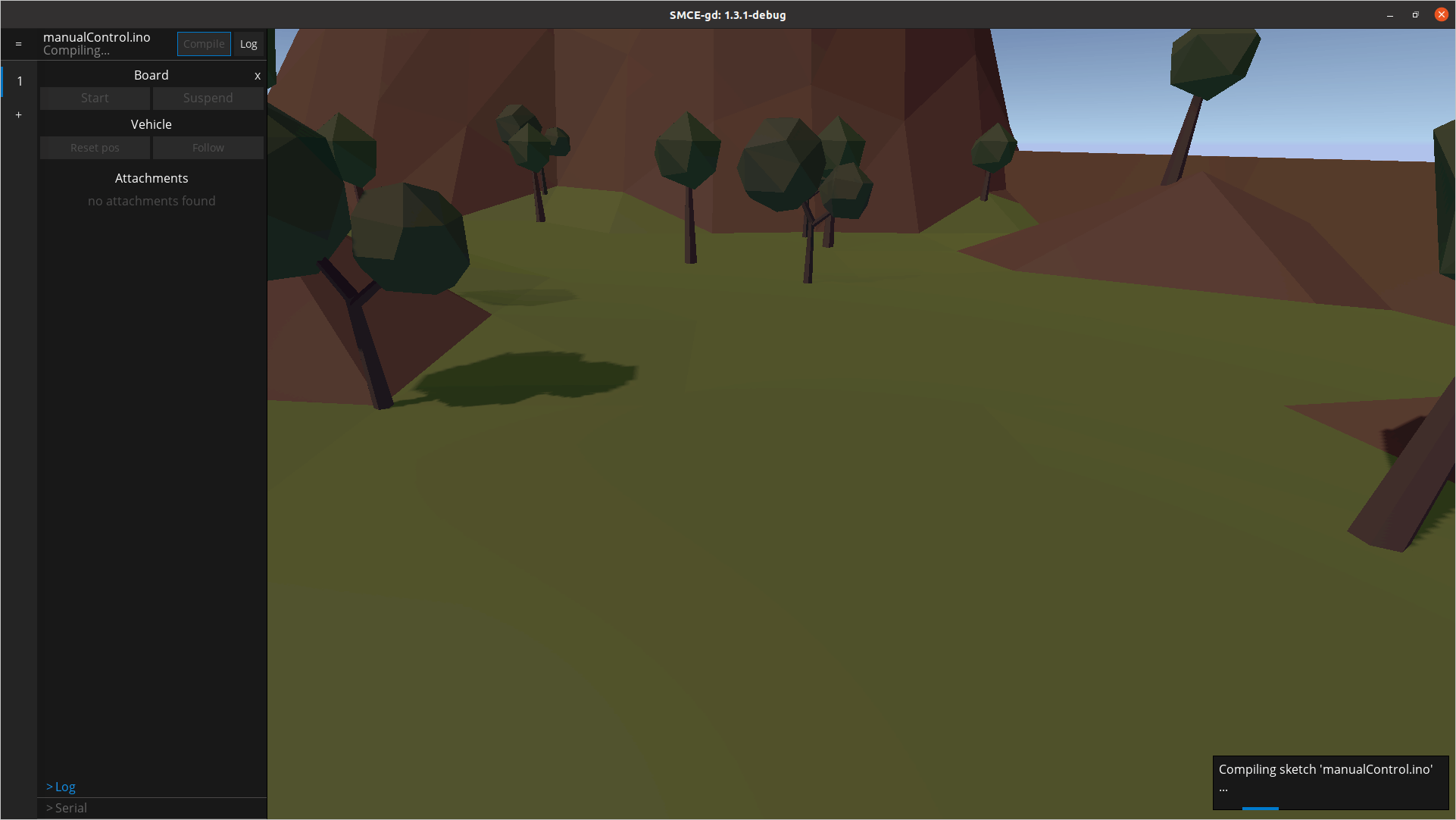
编译成功后,点击开始按钮。您会看到汽车在虚拟世界中弹出。酷吧?让我们开车吧!单击屏幕左下方的“串行”选项,键入并按键盘上的“Enter”。汽车将开始行驶。按下“跟随”选项,使相机随着汽车一起移动,并使用我们上面描述的简单命令进行操作。完成后,您可以单击停止。专业提示:您可能希望在函数结束时放置一个微小的延迟(例如),以避免占用您的 CPU 资源,因为仿真器将在您的草图中快速循环。floop()delay(1)
使用传感器
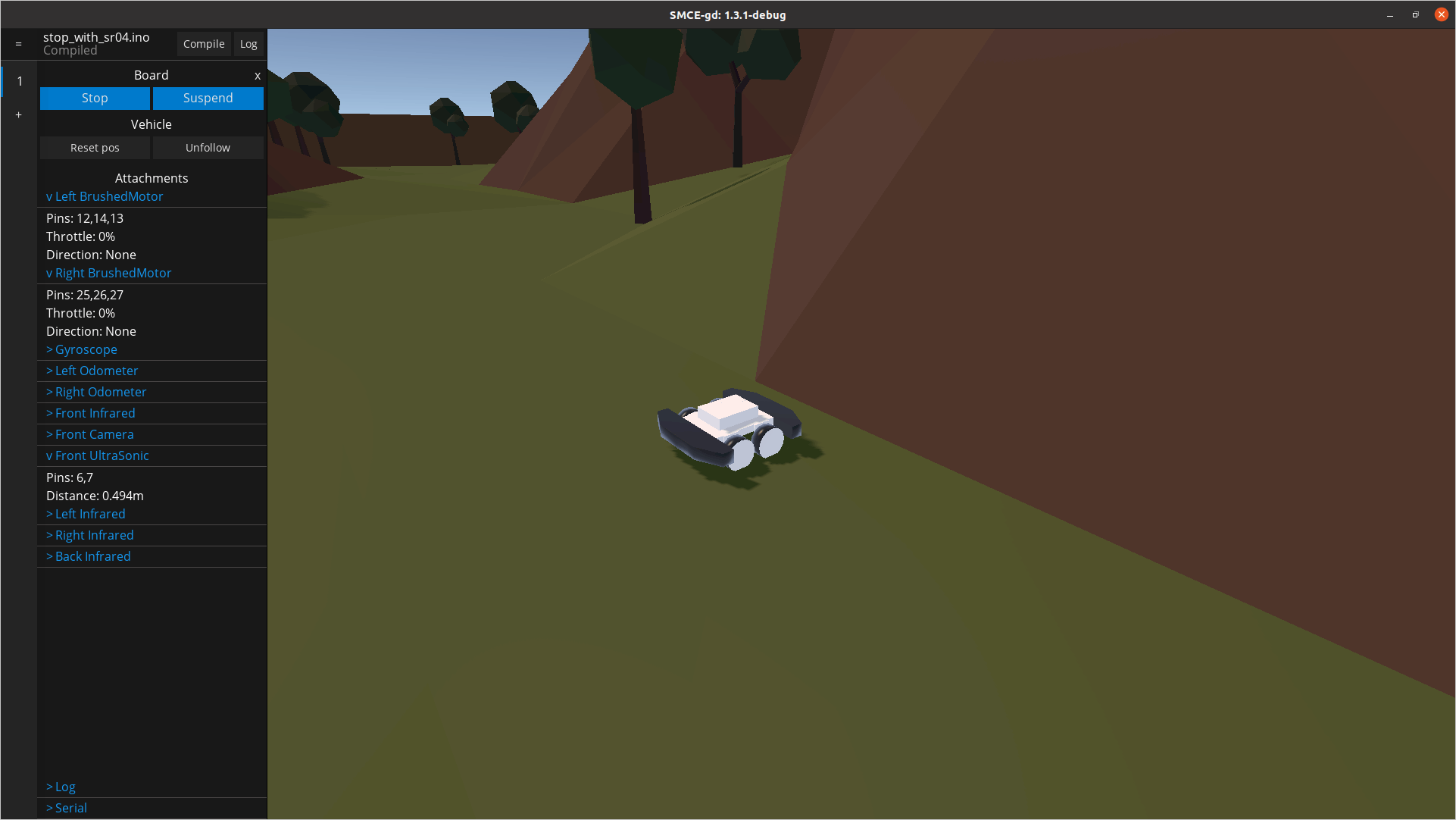
现在您已经了解了环境物理原理以及如何通过串行端口向汽车发送命令,让我们使用一些传感器让汽车自动移动。默认情况下,汽车预装了一堆方便的传感器。默认配置包括车辆前部的超声波传感器 ( SR04) ,连接到引脚 6 和 7。如果距离小于 70 厘米的障碍物,让我们使用传感器停止汽车。
#include

ArduinoRuntime arduinoRuntime;
BrushedMotor leftMotor{arduinoRuntime, smartcarlib::pins::v2::leftMotorPins};
BrushedMotor rightMotor{arduinoRuntime, smartcarlib::pins::v2::rightMotorPins};
DifferentialControl control{leftMotor, rightMotor};

SimpleCar car(control);

const int triggerPin           = 6; // D6
const int echoPin              = 7; // D7
const unsigned int maxDistance = 100;
SR04 front{arduinoRuntime, triggerPin, echoPin, maxDistance};

void setup()
{
  // Move the car with 50% of its full speed
  car.setSpeed(50);
}

void loop()
{
  const auto distance = front.getDistance();
  // When distance is `0` it means there's no obstacle detected
  if (distance > 0 && distance < 70) {
    car.setSpeed(0);
  }

#ifdef __SMCE__
  // Avoid over-using the CPU if we are running in the emulator
  delay(1);
#endif
}
加载草图并在模拟器中运行它。它会一直直行,直到遇到障碍物。您可以通过单击屏幕左侧的传感器读数来实时监控它们。在下面的屏幕截图中,我们可以看到,一旦遇到墙壁,电机就没有油门,并且检测到的距离在预期范围内。专业提示:如果按F3 ,您将获得传感器指向的位置及其范围的指示。这对于调试传感器输入特别有价值。
作为额外的真实感,传感器读数故意不完全准确并且包含噪声。默认设置中当前可用的传感器有:
- 车辆前部的一个SR04超声波传感器,距离相对较远,但其测量速度较慢且噪声较大。
- 四个 SHARP 红外传感器(例如GP2Y0A21 ),位于汽车侧面。它们的射程更短,但更准确、更快速。
- 两个方向里程表,每侧一个,用于测量汽车行驶了多少。
- 一个GY50陀螺仪,可以告诉您汽车的方向,或者更确切地说,以度数 [0, 360) 为单位的角位移。
- OV767X摄像头,可用于流式传输汽车所看到的内容。
连接性
通过串行端口发送命令并根据传感器输入使汽车自动行驶很有趣,但不可否认的是,您可以完成的任务是有限的。您经常需要您的车辆与“外部世界”进行通信,无论它可能是不同设备上的应用程序还是服务器。物理Smartcar平台围绕 ESP32 微控制器构建,因此它可以通过 WiFi 或蓝牙轻松连接到其他设备。SMCE 允许其用户通过WiFi 和 MQTT模拟连接。虽然 WiFi 库的模拟还没有完全实现,因为仍有工作要做,但应该不会超过一些#ifdef __SMCE__编写一个可在真实硬件和仿真器上无缝运行的 Arduino 草图。让我们看看如何编写一个简单的草图,通过 MQTT 消息控制汽车并广播遥测数据,即前超声波传感器的距离测量值。注意:虽然下面的草图在 SMCE 上运行良好,但它需要一些添加/更改才能在实际的 ESP32 上运行,主要是关于 WiFi 连接。
#include <MQTT.h>
#include <WiFi.h>

#include <Smartcar.h>

#ifndef __SMCE__
WiFiClient net;
#endif
MQTTClient mqtt;

ArduinoRuntime arduinoRuntime;
BrushedMotor leftMotor(arduinoRuntime, smartcarlib::pins::v2::leftMotorPins);
BrushedMotor rightMotor(arduinoRuntime, smartcarlib::pins::v2::rightMotorPins);
DifferentialControl control(leftMotor, rightMotor);

SimpleCar car(control);

const auto oneSecond = 1000UL;
const auto triggerPin = 6;
const auto echoPin = 7;
const auto maxDistance = 400;
SR04 front(arduinoRuntime, triggerPin, echoPin, maxDistance);

void setup() {
  Serial.begin(9600);
#ifdef __SMCE__
  // ================= 1
  // mqtt.begin("aerostun.dev", 1883, WiFi);
  mqtt.begin(WiFi); // Will connect to localhost
#else
  mqtt.begin(net);
#endif
  // ================= 2
  if (mqtt.connect("arduino", "public", "public")) {
    mqtt.subscribe("/smartcar/control/#", 1);
    mqtt.onMessage([](String topic, String message) {
      if (topic == "/smartcar/control/throttle") {
        car.setSpeed(message.toInt());
      } else if (topic == "/smartcar/control/steering") {
        car.setAngle(message.toInt());
      } else {
        Serial.println(topic + " " + message);
      }
    });
  }
}

void loop() {
  if (mqtt.connected()) {
    mqtt.loop();
    const auto currentTime = millis();
    static auto previousTransmission = 0UL;
    if (currentTime - previousTransmission >= oneSecond) {
      previousTransmission = currentTime;
      const auto distance = String(front.getDistance());
      // ================= 3
      mqtt.publish("/smartcar/ultrasound/front", distance);
    }
  }
#ifdef __SMCE__
  // Avoid over-using the CPU if we are running in the emulator
  delay(1);
#endif
}
我用内联注释突出显示了草图中的三个有趣点,然后是=================:
-
这是与 MQTT 代理建立连接的地方。如果没有传递参数,
begin那么它将连接到localhost. 您有责任在本地或远程主机上设置代理。 - 在这里,我们订阅我们感兴趣的主题,并定义一旦收到带有特定主题的消息将发生什么。
- 我们想提供一些反馈,因此我们每隔一秒发送/发布前视超声波传感器测量的距离。
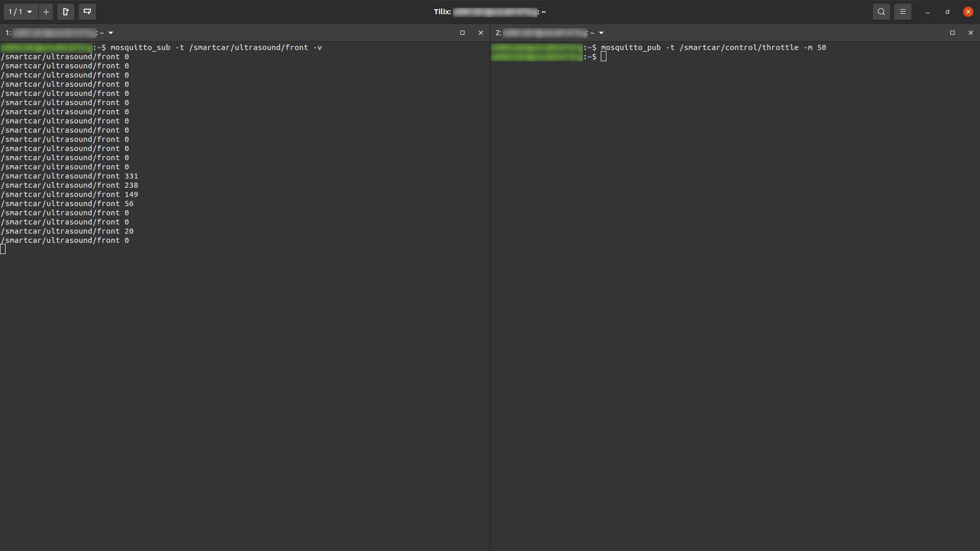
如果您使用的是 Ubuntu,Mosquitto是最容易设置的 MQTT 代理之一。我使用mosquitto_pub和mosquitto_sub实用程序订阅前超声波传感器测量并发送油门命令,如下面的屏幕截图所示。50一旦在/smartcar/control/throttle主题上得到适当的消息,汽车就开始加速行驶,并在/smartcar/ultrasound/front.
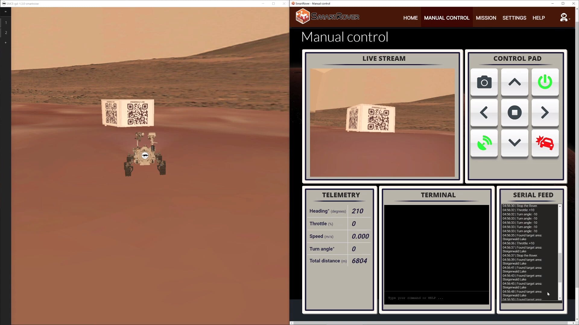
相机
当试图了解你的漫游者的环境时,传感器只能让你走这么远。SMCE 允许您获取虚拟世界的图像流。这样,您既可以在汽车的微控制器本身上进行一些非常简单的图像处理,也可以将图像流广播到功能更强大的设备并在那里进行图像处理。为简单起见,SMCE 仅支持Arduino_OV767X库,并且可以利用 MQTT 来广播流。让我们看一个草图,它为 MQTT 客户端侦听提供图像流/smartcar/camera。和之前一样,只是增加了摄像头流:
#include

#include <MQTT.h>
#include <WiFi.h>
#include <OV767X.h>

#include <Smartcar.h>

#ifndef __SMCE__
WiFiClient net;
#endif
MQTTClient mqtt;

ArduinoRuntime arduinoRuntime;
BrushedMotor leftMotor(arduinoRuntime, smartcarlib::pins::v2::leftMotorPins);
BrushedMotor rightMotor(arduinoRuntime, smartcarlib::pins::v2::rightMotorPins);
DifferentialControl control(leftMotor, rightMotor);

SimpleCar car(control);

const auto oneSecond = 1000UL;
const auto triggerPin = 6;
const auto echoPin = 7;
const auto maxDistance = 400;
SR04 front(arduinoRuntime, triggerPin, echoPin, maxDistance);

std::vector<char> frameBuffer;

void setup() {
  Serial.begin(9600);
  Camera.begin(QVGA, RGB888, 15);
  // ================= 1
  frameBuffer.resize(Camera.width() * Camera.height() * Camera.bytesPerPixel());
#ifdef __SMCE__
  // mqtt.begin("aerostun.dev", 1883, WiFi);
  mqtt.begin(WiFi); // Will connect to localhost
#else
  mqtt.begin(net);
#endif
  if (mqtt.connect("arduino", "public", "public")) {
    mqtt.subscribe("/smartcar/control/#", 1);
    mqtt.onMessage([](String topic, String message) {
      if (topic == "/smartcar/control/throttle") {
        car.setSpeed(message.toInt());
      } else if (topic == "/smartcar/control/steering") {
        car.setAngle(message.toInt());
      } else {
        Serial.println(topic + " " + message);
      }
    });
  }
}

void loop() {
  if (mqtt.connected()) {
    mqtt.loop();
    const auto currentTime = millis();
    static auto previousFrame = 0UL;
    // ================= 2
    if (currentTime - previousFrame >= 65) {
      previousFrame = currentTime;
      Camera.readFrame(frameBuffer.data());
      mqtt.publish("/smartcar/camera", frameBuffer.data(), frameBuffer.size(),
                   false, 0);
    }
    static auto previousTransmission = 0UL;
    if (currentTime - previousTransmission >= oneSecond) {
      previousTransmission = currentTime;
      const auto distance = String(front.getDistance());
      mqtt.publish("/smartcar/ultrasound/front", distance);
    }
  }
#ifdef __SMCE__
  // Avoid over-using the CPU if we are running in the emulator
  delay(1);
#endif
}
- 在堆上分配足够的内存以包含单个帧。
-
每
65毫秒,从相机中读取一帧并将其复制到frameBuffer. 然后通过 MQTT 广播它。
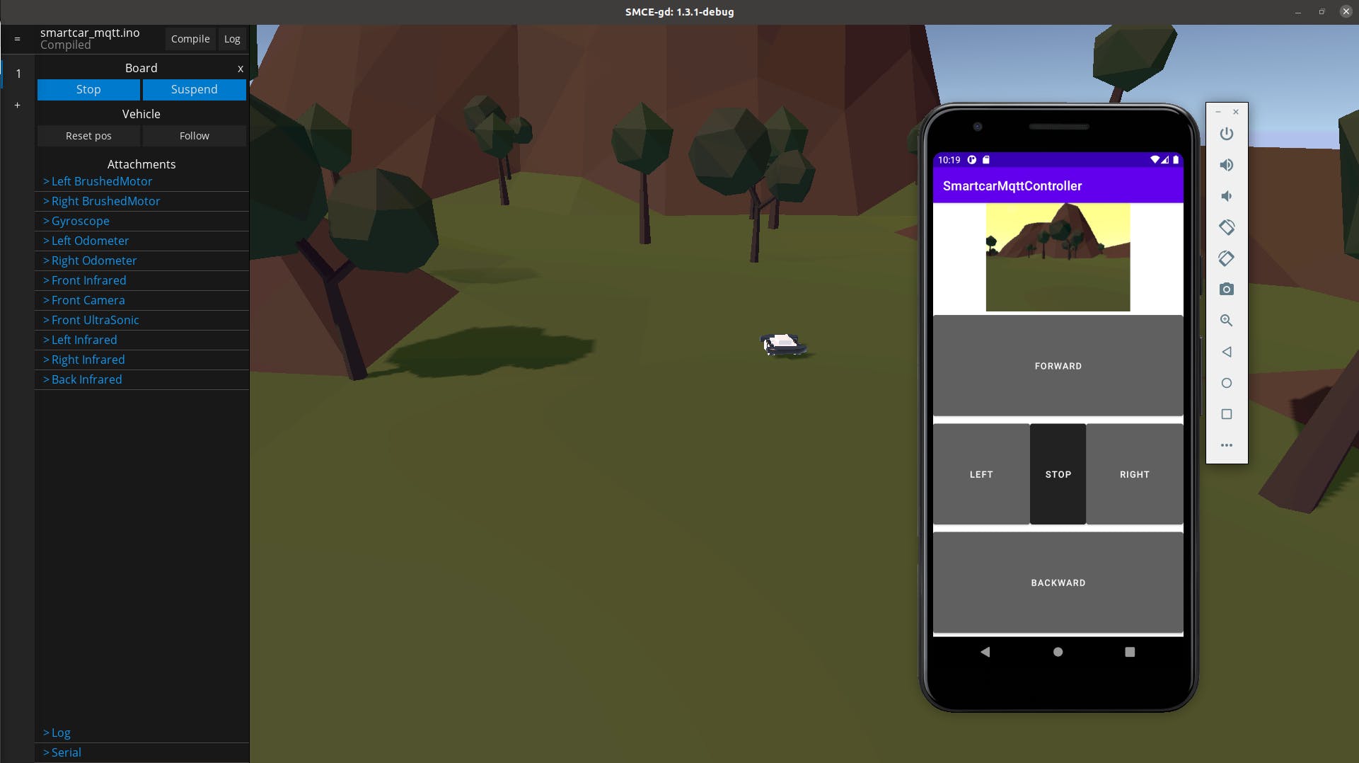
为了向您展示这在真实场景中会是什么样子,您可以使用参考 Android 应用程序通过 MQTT 消息控制汽车以及可视化图像流。它不是最漂亮的,但您将了解如何使用 JAVA 和 Android 完成事情的要点。
自定义传感器配置
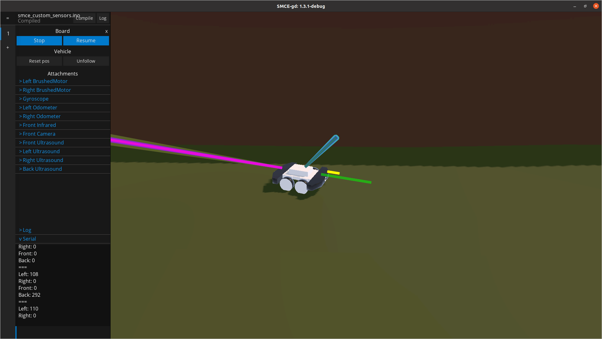
默认情况下,车辆预装了一组特定的传感器、执行器和可用引脚。这在 SMCE 的 wiki 中的车辆功能下进行了描述。要使用您自己的设置,您可以定义您的自定义配置,使用与您的草图json位于同一目录中的文件。假设我们想要一个允许我们通过串行端口驾驶汽车的草图(如前所述),从车辆的所有四个侧面测量距离并将它们发送给我们。你最终会得到一个如下图所示的草图:
#include

const int fSpeed   = 70;  // 70% of the full speed forward
const int bSpeed   = -70; // 70% of the full speed backward
const int lDegrees = -75; // degrees to turn left
const int rDegrees = 75;  // degrees to turn right
const unsigned long transmissionInterval = 100; // In milliseconds
const int maxDistance = 300;

ArduinoRuntime arduinoRuntime;
BrushedMotor leftMotor(arduinoRuntime, smartcarlib::pins::v2::leftMotorPins);
BrushedMotor rightMotor(arduinoRuntime, smartcarlib::pins::v2::rightMotorPins);
DifferentialControl control(leftMotor, rightMotor);

SimpleCar car(control);

// ================= 1
SR04 left(arduinoRuntime, 2, 3, maxDistance); // trigger and echo pin respectively
SR04 right(arduinoRuntime, 4, 5, maxDistance);
SR04 front(arduinoRuntime, 6, 7, maxDistance);
SR04 back(arduinoRuntime, 16, 17, maxDistance);

void setup()
{
  Serial.begin(9600);
}

void loop()
{
  static auto previousTransmission = 0UL;
  const auto currentTime = millis();
  // ================= 2
  if (currentTime > previousTransmission + transmissionInterval) {
    previousTransmission = currentTime;
    Serial.println("===");
    Serial.println("Left: " + String(left.getDistance()));
    Serial.println("Right: " + String(right.getDistance()));
    Serial.println("Front: " + String(front.getDistance()));
    Serial.println("Back: " + String(back.getDistance()));
  }

  handleInput();
#ifdef __SMCE__
  // Avoid over-using the CPU if we are running in the emulator
  delay(1);
#endif
}

void handleInput()
{
  if (Serial.available())
  {
    char input = Serial.read(); // read everything that has been received so far and log down
    // the last entry
    switch (input)
    {
      case 'l': // rotate counter-clockwise going forward
        car.setSpeed(fSpeed);
        car.setAngle(lDegrees);
        break;
      case 'r': // turn clock-wise
        car.setSpeed(fSpeed);
        car.setAngle(rDegrees);
        break;
      case 'f': // go ahead
        car.setSpeed(fSpeed);
        car.setAngle(0);
        break;
      case 'b': // go back
        car.setSpeed(bSpeed);
        car.setAngle(0);
        break;
      default: // if you receive something that you don't know, just stop
        car.setSpeed(0);
        car.setAngle(0);
    }
  }
}
-
在这里,我们定义了我们的传感器应该连接到的引脚。例如,
left超声波 (SR04) 传感器连接到引脚2和3。前者是触发销,后者是回声销。 -
我们通过串行端口“打印”出测量值,间隔由 的值指定
transmissionInterval。
默认设置不支持上面的草图,原因有两个:(a)默认汽车没有配备四个传感器,而SR04只有一个,(b)在典型 ESP32 板上可用的引脚在默认情况下不可用仿真板。幸运的是,我们可以改变它!我们需要做的第一件事是使所有必要的引脚可用,并确保它们是正确的类型(即数字或模拟)。在这里我们应该注意,由于技术原因,传感器的回波引脚必须指定为。以下是您应该遵循的步骤:1617SR04analog
-
在与您的草图相同的目录中创建一个空文件。
board_config.json - 获取SMCE 使用的默认板配置,以便我们可以在它的基础上进行构建(补丁)。
-
使用该
gpio_drivers属性来指定您的草图需要的所有引脚。注意:不要忘记您需要指定电机、里程表(如果您使用它们)、陀螺仪等所需的引脚。就我而言,我想移除一些我不使用的引脚(0和),1添加新的(16和17)并确保SR04传感器使用的所有引脚都处于正确的模式。
{
    "gpio_drivers": [
        { "pin": 2, "digital": true },
        { "pin": 3, "analog": true },
        { "pin": 4, "digital": true },
        { "pin": 5, "analog": true },
        { "pin": 6, "digital": true },
        { "pin": 7, "analog": true },
        { "pin": 16, "digital": true },
        { "pin": 17, "analog": true },

        { "pin": 12, "digital": true },
        { "pin": 13, "analog": true },
        { "pin": 14, "digital": true },

        { "pin": 18, "analog": true },

        { "pin": 25, "digital": true },
        { "pin": 26, "digital": true },
        { "pin": 27, "analog": true },

        { "pin": 34, "digital": true },
        { "pin": 35, "analog": true },
        { "pin": 85, "analog": true },
        { "pin": 135, "analog": true },

        { "pin": 39, "digital": true },
        { "pin": 36, "analog": true },
        { "pin": 86, "analog": true },
        { "pin": 136, "analog": true },

        { "pin": 250, "digital": true },

        { "pin": 205, "analog": true }
    ]
}
创建board_config.json指定仿真 Arduino 板上可用引脚的文件后,是时候设置您的车辆了。同样,我们将使用默认设置来获取灵感并相应地对其进行修补。
-
在与您的草图相同的目录中创建一个文件。
vehicle_config.json - 获取 SMCE 使用的默认车辆配置,以便我们在此基础上进行构建。
-
更改
slots您感兴趣的。在我的情况下,我想在和插槽上连接SR04传感器Left,使用与草图中相同的引脚,并确保这些引脚已经被.RightBackboard_config.json
{
   "slots": {
      "Left": {
         "class": "UltraSonic",
         "name": "Left Ultrasound",
         "props": {
            "trigger_pin": 2,
            "echo_pin": 3
         }
      },
      "Right": {
         "class": "UltraSonic",
         "name": "Right Ultrasound",
         "props": {
            "trigger_pin": 4,
            "echo_pin": 5
         }
      },
      "FrontTop": {
         "class": "UltraSonic",
         "name": "Front Ultrasound",
         "props": {
            "trigger_pin": 6,
            "echo_pin": 7
         }
      },
      "Back": {
         "class": "UltraSonic",
         "name": "Back Ultrasound",
         "props": {
            "trigger_pin": 16,
            "echo_pin": 17
         }
      }
   }
}
专业提示:如果您想完全覆盖任何配置,可以将from_scratch顶级元素添加为true. 如果您想完全移除占用您根本不使用的插槽的摄像头或其他传感器,这将非常有用。引脚也是如此。例如,下面的配置将创建一辆汽车,其后侧仅配备一个超声波传感器和一对电机。没有别的,没有相机,没有里程表,没有陀螺仪。
{
   "from_scratch": true,
   "vehicle": "RayCar",
   "slots": {
      "Back": {
         "class": "UltraSonic",
         "name": "Back Ultrasound",
         "props": {
            "trigger_pin": 16,
            "echo_pin": 17
         }
      }
   },
   "builtin": {
      "Left BrushedMotor": {
         "forward_pin": 12,
         "backward_pin": 14,
         "enable_pin": 13
      },
      "Right BrushedMotor": {
         "forward_pin": 25,
         "backward_pin": 26,
         "enable_pin": 27
      }
   }
}
修改环境
。
- 生存危机-Arduino角色扮演游戏模拟器 0次下载
- Wokwi Arduino模拟器介绍 2次下载
- 用于飞行模拟器的带Arduino的LCD面板 0次下载
- 停车模拟器开源硬件 0次下载
- 基于Arduino Nano R3的DIY 2D运动赛车模拟器 0次下载
- 带有Arduino的纠缠量子比特模拟器 0次下载
- Arduino Altair 8800模拟器 0次下载
- 通过在线模拟器上的Arduino操作伺服电机 0次下载
- DIY 2D运动赛车模拟器 2次下载
- Arduino模拟器开源分享 2次下载
- 一个真正的Arduino UNO电子宠物模拟器 1次下载
- 用Arduino板和LDR单元制作自动存在模拟器 0次下载
- 基于DSP的电磁脉冲模拟器控制系统设计方案 13次下载
- 倍福基于PC和EtherCAT的控制平台控制的赛车模拟器 13次下载
- 汽车驾驶模拟器新一代实时场景系统的开发 55次下载
- 聊聊英飞凌的汽车模块HybridPACK 1584次阅读
- 华为eNSP模拟器安装教程 2091次阅读
- 华为新版模拟器eNSP Lite安装攻略 5480次阅读
- R-Car DNN模拟器的介绍 639次阅读
- 如何对PNET 模拟器进行初始化安装 1222次阅读
- 使用LED作为模拟输出的汽车警报模拟器电路 1460次阅读
- 一个由Arduino驱动的数字时钟详解 3224次阅读
- HarmonyOS本地模拟器的版本演进与使用方法 5689次阅读
- 基于CPLD芯片在汽车驾驶模拟器系统中的应用研究 2147次阅读
- 基于AT89C52单片机和传感器实现汽车驾驶模拟器单片机系统的应用方案 2541次阅读
- 5G通信信号模拟器系统软件的设计方法 6035次阅读
- 基于QEMU系统模拟器Xilinx/QEMU的运行与调试 8411次阅读
- 基于TL431的电动汽车多节串联锂电池模拟器 6698次阅读
- 一种基于FPGA嵌入式系统的雷达信号模拟器的实现 2444次阅读
- 基于FPGA的飞行模拟器通信接口设计 2405次阅读

 上传资料赚积分
下载排行
本周
- 1山景DSP芯片AP8248A2数据手册
- 1.06 MB | 532次下载 | 免费
- 2RK3399完整板原理图(支持平板,盒子VR)
- 3.28 MB | 339次下载 | 免费
- 3TC358743XBG评估板参考手册
- 1.36 MB | 330次下载 | 免费
- 4DFM软件使用教程
- 0.84 MB | 295次下载 | 免费
- 5元宇宙深度解析—未来的未来-风口还是泡沫
- 6.40 MB | 227次下载 | 免费
- 6迪文DGUS开发指南
- 31.67 MB | 194次下载 | 免费
- 7元宇宙底层硬件系列报告
- 13.42 MB | 182次下载 | 免费
- 8FP5207XR-G1中文应用手册
- 1.09 MB | 178次下载 | 免费
本月
- 1OrCAD10.5下载OrCAD10.5中文版软件
- 0.00 MB | 234315次下载 | 免费
- 2555集成电路应用800例(新编版)
- 0.00 MB | 33566次下载 | 免费
- 3接口电路图大全
- 未知 | 30323次下载 | 免费
- 4开关电源设计实例指南
- 未知 | 21549次下载 | 免费
- 5电气工程师手册免费下载(新编第二版pdf电子书)
- 0.00 MB | 15349次下载 | 免费
- 6数字电路基础pdf(下载)
- 未知 | 13750次下载 | 免费
- 7电子制作实例集锦 下载
- 未知 | 8113次下载 | 免费
- 8《LED驱动电路设计》 温德尔著
- 0.00 MB | 6656次下载 | 免费
总榜
- 1matlab软件下载入口
- 未知 | 935054次下载 | 免费
- 2protel99se软件下载(可英文版转中文版)
- 78.1 MB | 537798次下载 | 免费
- 3MATLAB 7.1 下载 (含软件介绍)
- 未知 | 420027次下载 | 免费
- 4OrCAD10.5下载OrCAD10.5中文版软件
- 0.00 MB | 234315次下载 | 免费
- 5Altium DXP2002下载入口
- 未知 | 233046次下载 | 免费
- 6电路仿真软件multisim 10.0免费下载
- 340992 | 191187次下载 | 免费
- 7十天学会AVR单片机与C语言视频教程 下载
- 158M | 183279次下载 | 免费
- 8proe5.0野火版下载(中文版免费下载)
- 未知 | 138040次下载 | 免费


 工商网监
工商网监
评论