 电子发烧友App


 创作
创作 发文章
发文章 发帖
发帖  提问
提问  发资料
发资料 发视频
发视频资料介绍
描述
介绍
前段时间,我在寻找一种易于理解的 VHDL UART 设计,但令人惊讶的是我找不到。也许我搜索得不够好,但无论如何,我认为这将是我的技术爱好博客的一个很好的起点。所以,这是我的第一个项目,请欢迎使用 Basys 3 板的 VHDL UART 接口。
这种设计允许将位从电路板传输到计算机终端,并从终端接收位到电路板。您可以通过按下板上的按钮将数据从板传输到终端。可以使用用户开关设置发送位,并且可以在用户 LED 上检查接收位。
UART接口总结
如果您是 UART 的完全初学者,我建议您在此处查看此 wiki 页面。
由于 UART 接口是串行接口,因此发送器会逐位发送数据。同时,接收器必须捕获每个位并将其转换为并行数据。该标准的另一个重要特征是波特率,它定义了 UART 每秒可以传输多少位。该接口允许许多不同的波特率,但在这个项目中我使用 115200 波特。
让我们看看这个项目中使用的时间框架:

我使用了最简单的 UART 版本,如下所述:
- 起始位 ('0')
- 8 个数据位
- 无奇偶校验位
- 一位停止位 ('1')
项目文件
这是 Vivado 中的项目树:
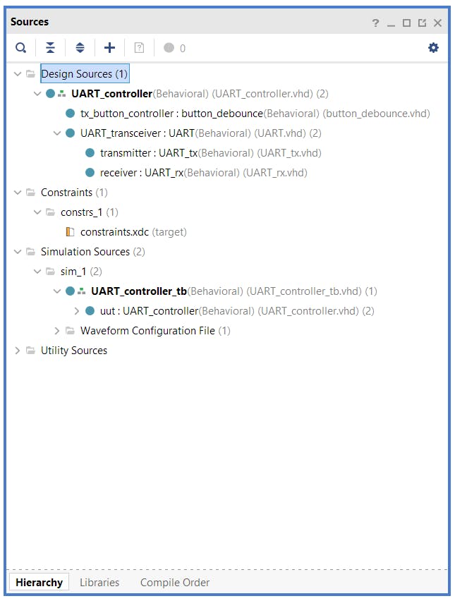
-
UART_controller.vhd- 将设计与外界联系起来的顶级文件 -
button_debounce.vhd- 将发射按钮连接到项目的其余部分,并防止每次按下多次启动 -
UART.vhd- 将 tx 和 rx 文件组合在一起 -
UART_tx.vhd- 包含所有发送器逻辑 -
UART_rx.vhd- 包含所有接收器逻辑 -
constrains.xdc- 包含引脚连接和主时钟频率 -
UART_controller_tb.vhd- 这是设计的测试平台
项目的主要部分位于UART_tx.vhd和UART_rx.vhd文件中。这些文件及其逻辑将在下一节中详细讨论。
如果您更喜欢先构建一个项目并对芯片进行编程,您可以跳到创建项目部分并在阅读其余的理论部分之前先玩一下电路板。
发射机
是UART_tx.vhd一个传输模块。这是框图:
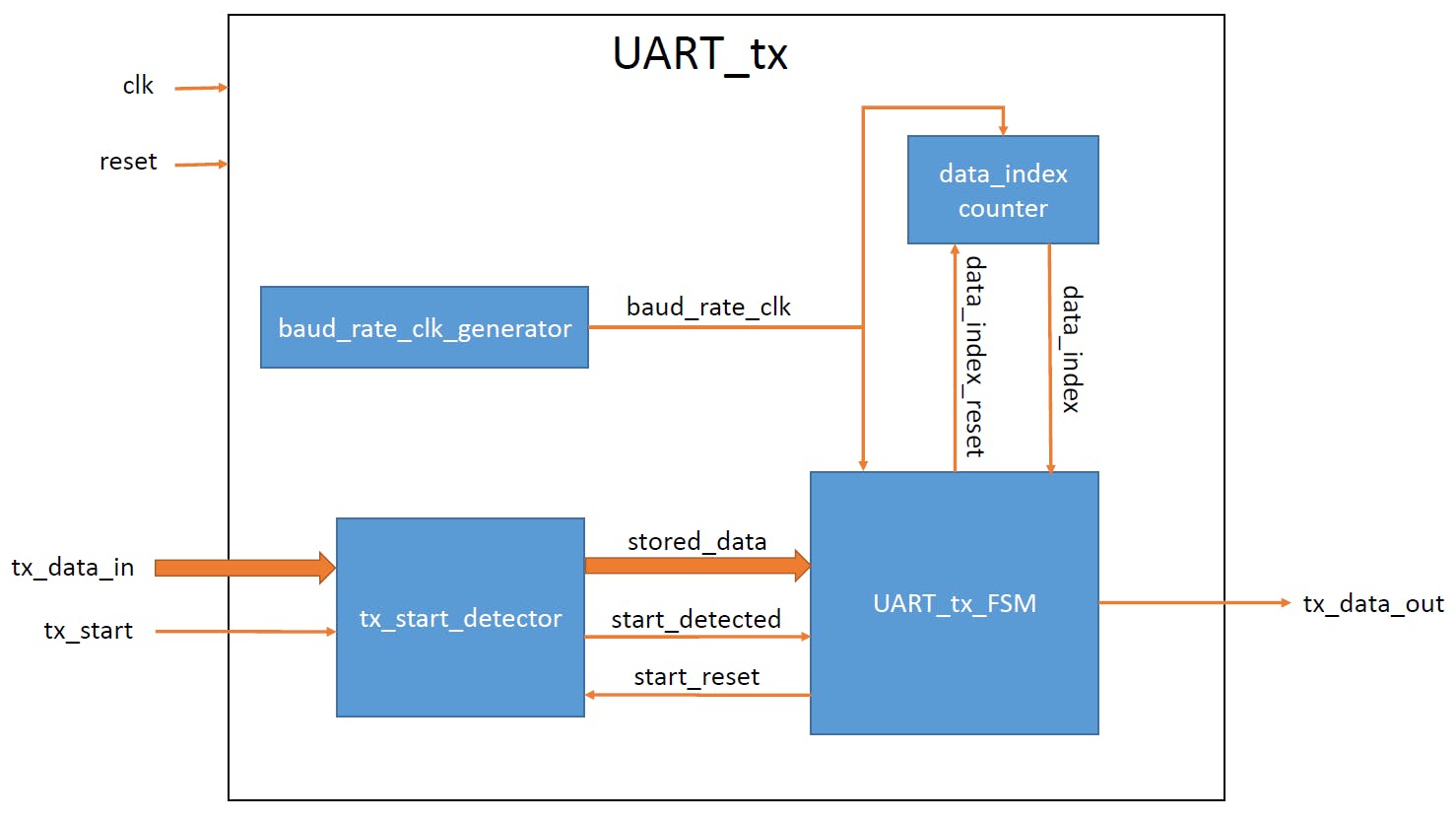
每个蓝色块代表UART_tx.vhd文件中的一个进程。
baud_rate_clk_generator通过在计数器计数主时钟的滴答时设置信号来生成 UART 波特率时钟。该常数反映了主时钟与波特率之间的比率。baud_rate_clkBAUD_CLK_TICKSBAUD_CLK_TICKS
tx_start_detector在主时钟频率上工作并捕捉tx_start信号中的短脉冲(一个时钟周期长)并将其保留在UART_tx_FSM. tx_start_detector需要,因为UART_tx_FSM工作在波特率频率上,但button_debounce模块每按一下按钮就会产生一个主时钟周期长脉冲。start_detected保留发生此类事件的信息。的第二个目的tx_start_detector是保护传输数据。stored_data保持传输过程中保存的传输数据。
data_index_counter是一个从 0 到 7 的简单计数器,用于处理波特率频率。它用于执行并行数据(stored_data)和串行输出(tx_data_out)之间的转换。该data_index信号用于UART_tx_FSM遍历stored_data向量并一一发送比特。
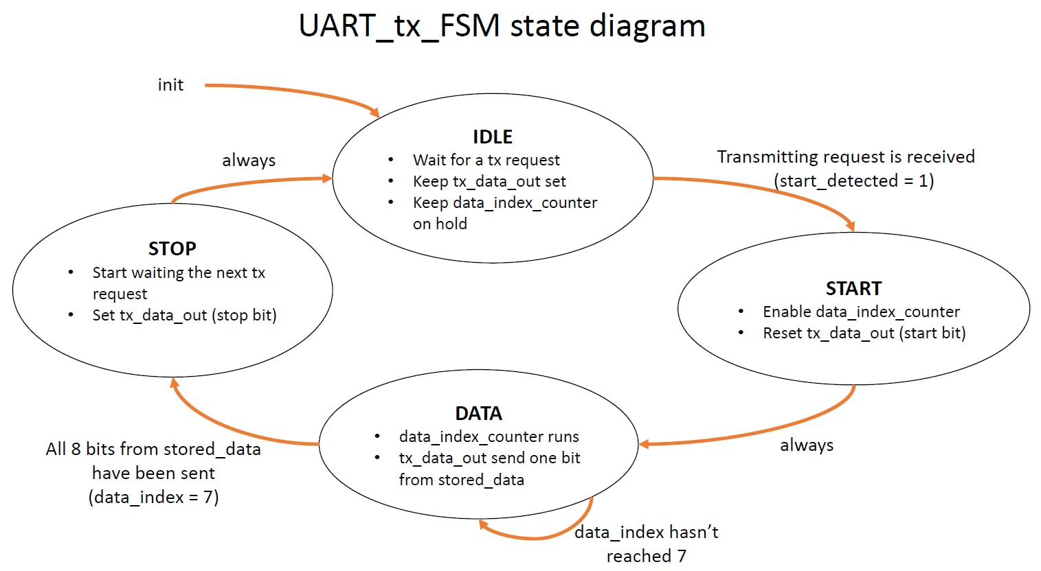
UART_tx_FSM代表一个有限状态机,它有四种状态(IDLE、START、DATA、STOP)。这是UART_tx_FSM块的状态图:
文件代码UART_tx.vhd:
library ieee;
use ieee.std_logic_1164.all;
use ieee.numeric_std.all;


entity UART_tx is

    generic(
        BAUD_CLK_TICKS: integer := 868); -- clk/baud_rate (100 000 000 / 115 200 = 868.0555)

    port(
        clk            : in  std_logic;
        reset          : in  std_logic;
        tx_start       : in  std_logic;
        tx_data_in     : in  std_logic_vector (7 downto 0);
        tx_data_out    : out std_logic
        );
end UART_tx;


architecture Behavioral of UART_tx is

    type tx_states_t is (IDLE, START, DATA, STOP);
    signal tx_state  : tx_states_t := IDLE;


    signal baud_rate_clk     : std_logic:= '0';

    signal data_index        : integer range 0 to 7 := 0;
    signal data_index_reset  : std_logic := '1';
    signal stored_data       : std_logic_vector(7 downto 0) := (others=>'0');

    signal start_detected    : std_logic := '0';
    signal start_reset       : std_logic := '0';

begin


-- The baud_rate_clk_generator process generates the UART baud rate clock by
-- setting the baud_rate_clk signal when the counter counts BAUD_CLK_TICKS
-- ticks of the master clk. The BAUD_CLK_TICKS constant is specified in
-- the package and reflects the ratio between the master clk and the baud rate.

    baud_rate_clk_generator: process(clk)
    variable baud_count: integer range 0 to (BAUD_CLK_TICKS - 1) := (BAUD_CLK_TICKS - 1);
    begin
        if rising_edge(clk) then
            if (reset = '1') then
                baud_rate_clk <= '0';
                baud_count := (BAUD_CLK_TICKS - 1);
            else
                if (baud_count = 0) then
                    baud_rate_clk <= '1';
                    baud_count := (BAUD_CLK_TICKS - 1);
                else
                    baud_rate_clk <= '0';
                    baud_count := baud_count - 1;
                end if;
            end if;
        end if;
    end process baud_rate_clk_generator;


-- The tx_start_detector process works on the master clk frequency and catches
-- short (one clk cycle long) impulses in the tx_start signal and keeps it for
-- the UART_tx_FSM. tx_start_detector is needed because the UART_tx_FSM works on
-- the baud rate frequency, but the button_debounce module generates one master clk
-- cycle long impulse per one button push. start_detected keeps the information that
-- such event has occurred.
-- The second purpose of tx_start_detector is to secure the transmitting data.
-- stored_data keeps the transmitting data saved during the transmission.

    tx_start_detector: process(clk)
    begin
        if rising_edge(clk) then
            if (reset ='1') or (start_reset = '1') then
                start_detected <= '0';
            else
                if (tx_start = '1') and (start_detected = '0') then
                    start_detected <= '1';
                    stored_data <= tx_data_in;
                end if;
            end if;
        end if;
    end process tx_start_detector;


-- The data_index_counter process is a simple counter from 0 to 7 working on the baud
-- rate frequency. It is used to perform transformation between the parallel
-- data (stored_data) and the serial output (tx_data_out).
-- The data_index signal is used in UART_tx_FSM to go over the stored_data vector
-- and send the bits one by one.

    data_index_counter: process(clk)
    begin
        if rising_edge(clk) then
            if (reset = '1') or (data_index_reset = '1') then
                data_index <= 0;
            elsif (baud_rate_clk = '1') then
                data_index <= data_index + 1;
            end if;
        end if;
    end process data_index_counter;


-- The UART_FSM_tx process represents a Finite State Machine which has
-- four states (IDLE, START, DATA, STOP). See inline comments for more details.

    UART_tx_FSM: process(clk)
    begin
        if rising_edge(clk) then
            if (reset = '1') then
                tx_state <= IDLE;
                data_index_reset <= '1';   -- keep data_index_counter on hold
                start_reset <= '1';        -- keep tx_start_detector on hold
                tx_data_out <= '1';        -- keep tx line set along the standard
            else
                if (baud_rate_clk = '1') then   -- the FSM works on the baud rate frequency
                    case tx_state is

                        when IDLE =>

                            data_index_reset <= '1';    -- keep data_index_counter on hold
                            start_reset <= '0';         -- enable tx_start_detector to wait for starting impulses
                            tx_data_out <= '1';         -- keep tx line set along the standard

                            if (start_detected = '1') then
                                tx_state <= START;
                            end if;

                        when START =>

                            data_index_reset <= '0';   -- enable data_index_counter for DATA state
                            tx_data_out <= '0';        -- send '0' as a start bit

                            tx_state <= DATA;

                        when DATA =>

                            tx_data_out <= stored_data(data_index);   -- send one bit per one baud clock cycle 8 times

                            if (data_index = 7) then
                                data_index_reset <= '1';              -- disable data_index_counter when it has reached 8
                                tx_state <= STOP;
                            end if;

                        when STOP =>

                            tx_data_out <= '1';     -- send '1' as a stop bit
                            start_reset <= '1';     -- prepare tx_start_detector to be ready detecting the next impuls in IDLE

                            tx_state <= IDLE;

                        when others =>
                            tx_state <= IDLE;
                    end case;
                end if;
            end if;
        end if;
    end process UART_tx_FSM;


end Behavioral;
接收者
是UART_rx.vhd接收模块。这是框图:
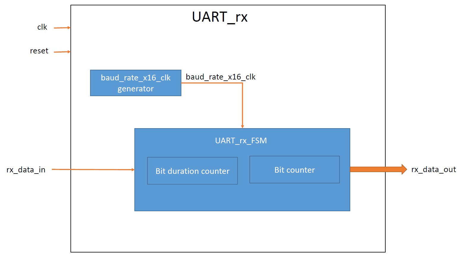
与这里相反UART_tx,我在 FSM 中内置了计数器(通过过程中的变量,参见代码)。我这样做只是为了演示在创建带有计数器的 FSM 时的不同方法。第一种方式(tx)在硬件上更快,但第二种方式更容易在 VHDL 中实现。
baud_rate_x16_clk_generator生成一个过采样时钟。该baud_rate_x16_clk信号比波特率时钟快 16 倍。需要进行过采样以将捕获点置于接收位持续时间的中间。该BAUD_X16_CLK_TICKS常数反映了主时钟与 x16 波特率之间的比率。
UART_rx_FSM代表一个有限状态机,它有四种状态(IDLE、START、DATA、STOP)。这是UART_rx_FSM块的状态图:
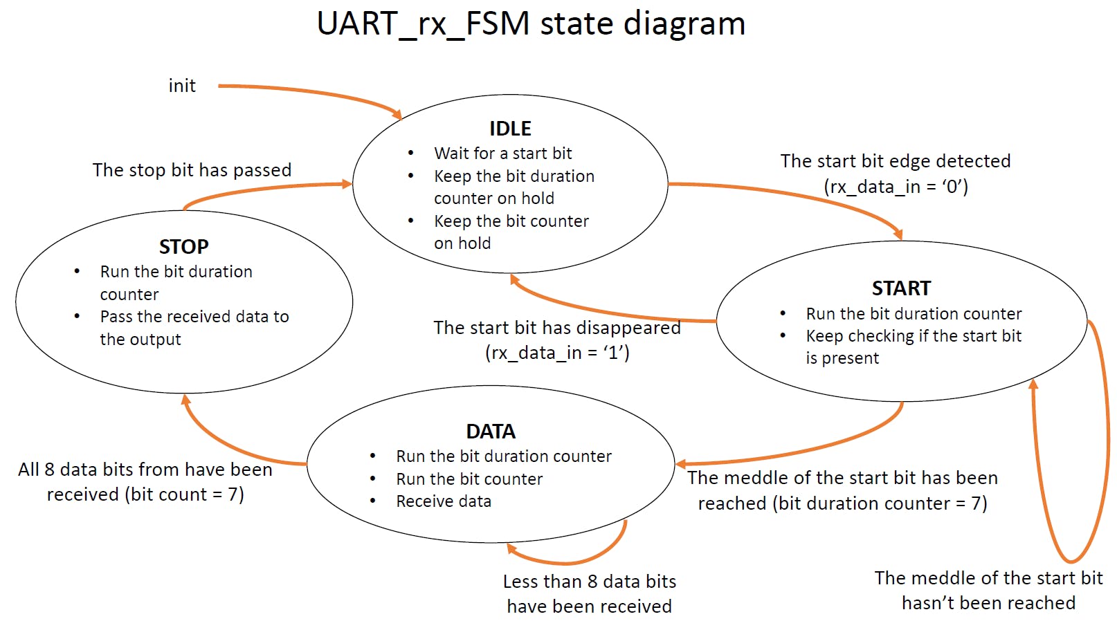
位持续时间计数器工作baud_rate_x16_clk
这是UART_rx.vhd文件的代码:
library ieee;
use ieee.std_logic_1164.all;
use ieee.numeric_std.all;


entity UART_rx is

    generic(
        BAUD_X16_CLK_TICKS: integer := 54); -- (clk / baud_rate) / 16 => (100 000 000 / 115 200) / 16 = 54.25

    port(
        clk            : in  std_logic;
        reset          : in  std_logic;
        rx_data_in     : in  std_logic;
        rx_data_out    : out std_logic_vector (7 downto 0)
        );
end UART_rx;


architecture Behavioral of UART_rx is

    type rx_states_t is (IDLE, START, DATA, STOP);
    signal rx_state: rx_states_t := IDLE;

    signal baud_rate_x16_clk  : std_logic := '0';
    signal rx_stored_data     : std_logic_vector(7 downto 0) := (others => '0');


begin


-- The baud_rate_x16_clk_generator process generates an oversampled clock.
-- The baud_rate_x16_clk signal is 16 times faster than the baud rate clock.
-- Oversampling is needed to put the capture point at the middle of duration of
-- the receiving bit.
-- The BAUD_X16_CLK_TICKS constant reflects the ratio between the master clk
-- and the x16 baud rate.

    baud_rate_x16_clk_generator: process(clk)
    variable baud_x16_count: integer range 0 to (BAUD_X16_CLK_TICKS - 1) := (BAUD_X16_CLK_TICKS - 1);
    begin
        if rising_edge(clk) then
            if (reset = '1') then
                baud_rate_x16_clk <= '0';
                baud_x16_count := (BAUD_X16_CLK_TICKS - 1);
            else
                if (baud_x16_count = 0) then
                    baud_rate_x16_clk <= '1';
                    baud_x16_count := (BAUD_X16_CLK_TICKS - 1);
                else
                    baud_rate_x16_clk <= '0';
                    baud_x16_count := baud_x16_count - 1;
                end if;
            end if;
        end if;
    end process baud_rate_x16_clk_generator;


-- The UART_rx_FSM process represents a Finite State Machine which has
-- four states (IDLE, START, DATA, STOP). See inline comments for more details.

    UART_rx_FSM: process(clk)
        variable bit_duration_count : integer range 0 to 15 := 0;
        variable bit_count          : integer range 0 to 7  := 0;
    begin
        if rising_edge(clk) then
            if (reset = '1') then
                rx_state <= IDLE;
                rx_stored_data <= (others => '0');
                rx_data_out <= (others => '0');
                bit_duration_count := 0;
                bit_count := 0;
            else
                if (baud_rate_x16_clk = '1') then     -- the FSM works 16 times faster the baud rate frequency
                    case rx_state is

                        when IDLE =>

                            rx_stored_data <= (others => '0');    -- clean the received data register
                            bit_duration_count := 0;              -- reset counters
                            bit_count := 0;

                            if (rx_data_in = '0') then             -- if the start bit received
                                rx_state <= START;                 -- transit to the START state
                            end if;

                        when START =>

                            if (rx_data_in = '0') then             -- verify that the start bit is preset
                                if (bit_duration_count = 7) then   -- wait a half of the baud rate cycle
                                    rx_state <= DATA;              -- (it puts the capture point at the middle of duration of the receiving bit)
                                    bit_duration_count := 0;
                                else
                                    bit_duration_count := bit_duration_count + 1;
                                end if;
                            else
                                rx_state <= IDLE;                  -- the start bit is not preset (false alarm)
                            end if;

                        when DATA =>

                            if (bit_duration_count = 15) then                -- wait for "one" baud rate cycle (not strictly one, about one)
                                rx_stored_data(bit_count) <= rx_data_in;     -- fill in the receiving register one received bit.
                                bit_duration_count := 0;
                                if (bit_count = 7) then                      -- when all 8 bit received, go to the STOP state
                                    rx_state <= STOP;
                                    bit_duration_count := 0;
                                else
                                    bit_count := bit_count + 1;
                                end if;
                            else
                                bit_duration_count := bit_duration_count + 1;
                            end if;

                        when STOP =>

                            if (bit_duration_count = 15) then      -- wait for "one" baud rate cycle
                                rx_data_out <= rx_stored_data;     -- transer the received data to the outside world
                                rx_state <= IDLE;
                            else
                                bit_duration_count := bit_duration_count + 1;
                            end if;

                        when others =>
                            rx_state <= IDLE;
                    end case;
                end if;
            end if;
        end if;
    end process UART_rx_FSM;

end Behavioral;
按钮控制器
为了从 Basys 3 板向计算机终端发送一个位,我们需要设置板开关并按下按钮。此时我们需要确保发送位。为此,button_debounce.vhd文件来了。
这是模块的框图:
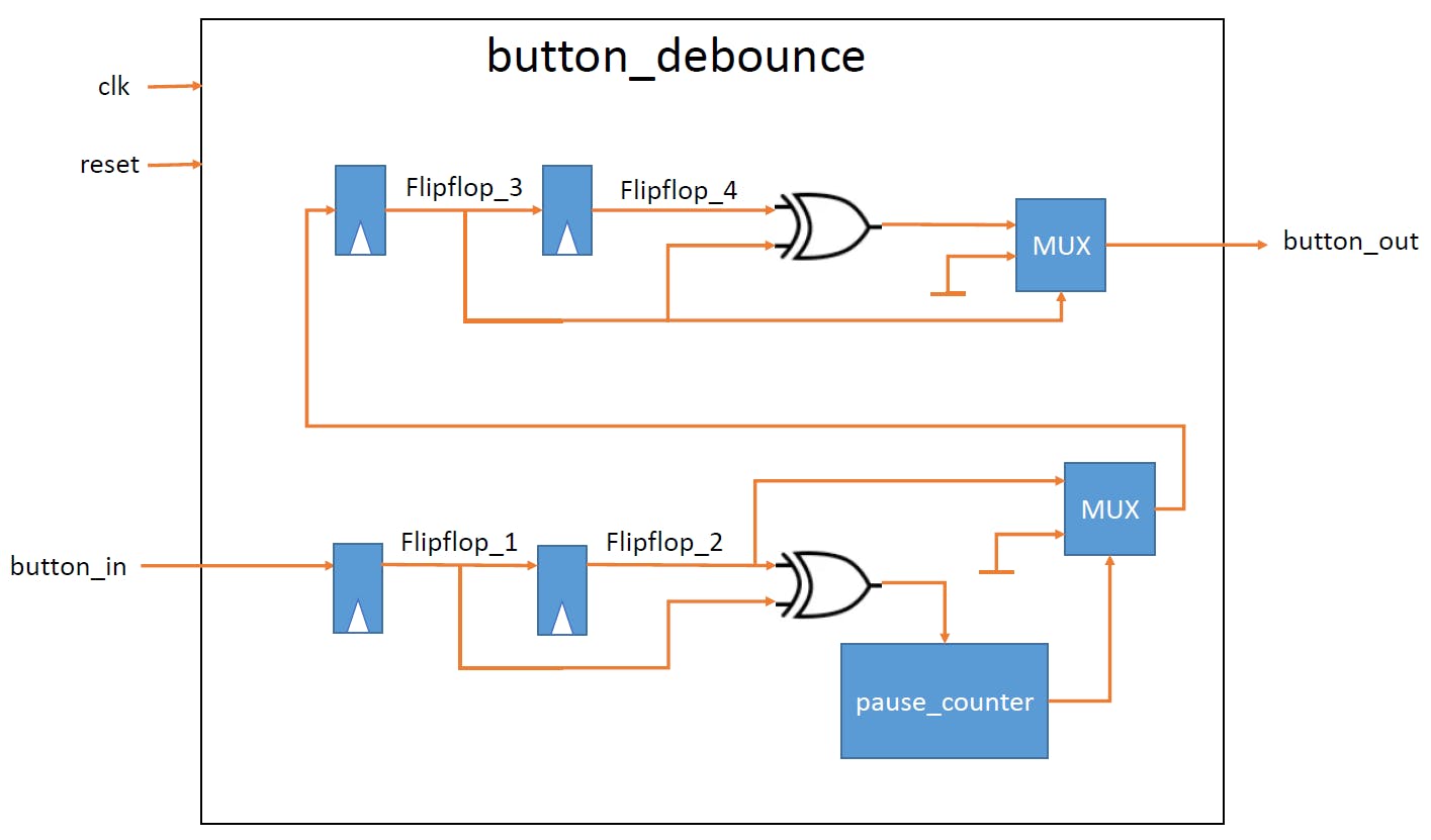
如果输入发生变化,则flipflop_1和flipflop_2信号会有所不同。button_in差异触发pause_counter将button_in信号从触发器 2 传递到触发器 3,但在COUNTER_SIZE主时钟周期之后。这允许button_in信号在通过之前稳定在某个状态。
和信号flipflop_3有flipflop_4一个主时钟周期延迟。需要延迟来在button_out输出端创建一个短(一个主时钟周期长)脉冲。完成pause_counter后,flipflop_3信号获取button_in信息。那一刻flipflop_4还没有改变。这会在button_out一个主时钟周期的输出上创建“1”,仅当flipflop_3为“1”时(按钮已被按下,未释放)。
这是模块的代码:
library ieee;
use ieee.std_logic_1164.all;
use ieee.numeric_std.all;


entity button_debounce is
    generic (
            COUNTER_SIZE : integer := 10_000
            );
    port ( clk        : in  std_logic;
           reset      : in  std_logic;
           button_in  : in  std_logic;
           button_out : out std_logic);
end button_debounce;


architecture Behavioral of button_debounce is

    signal flipflop_1       : std_logic := '0';     -- output of flip-flop 1
    signal flipflop_2       : std_logic := '0';     -- output of flip-flop 2
    signal flipflop_3       : std_logic := '0';     -- output of flip-flop 3
    signal flipflop_4       : std_logic := '0';     -- output of flip-flop 4
    signal count_start      : std_logic := '0';

begin

-- The input_flipflops process creates two serial flip-flops (flip-flop 1 and
-- flip-flop 2). The signal from button_in passes them one by one. If flip_flop_1
-- and flip_flop_2 are different, it means the button has been activated, and
-- count_start becomes '1' for one master clock cycle.

    input_flipflops: process(clk)
    begin
        if rising_edge(clk) then
            if (reset = '1') then
                flipflop_1 <= '0';
                flipflop_2 <= '0';
            else
                flipflop_1 <= button_in;
                flipflop_2 <= flipflop_1;
            end if;
        end if;
    end process input_flipflops;


-- The count_start signal triggers the pause_counter process to start counting

    count_start <= flipflop_1 xor flipflop_2;


-- The pause_counter process passes the button_in signal farther from flip-flop 2
-- to flip-flop 3, but after COUNTER_SIZE master clock cycles. This allows
-- the button_in signal to stabilize in a certain state before being passed to the output.

    pause_counter: process(clk)
        variable count: integer range 0 to COUNTER_SIZE := 0;
    begin
        if rising_edge(clk) then
            if (reset = '1') then
                count := 0;
                flipflop_3 <= '0';
            else
                if (count_start = '1') then
                    count := 0;
                elsif (count < COUNTER_SIZE) then
                    count := count + 1;
                else
                    flipflop_3 <= flipflop_2;
                end if;
            end if;
        end if;
    end process pause_counter;


-- the purpose of the output_flipflop process is creating another flip-flop (flip-flop 4),
-- which creates a delay between the flipflop_3 and flipflop_4 signals. The delay is
-- one master clock cycle long.

    output_flipflop: process(clk)
    begin
        if rising_edge(clk) then
            if (reset = '1') then
                flipflop_4 <= '0';
            else
                flipflop_4 <= flipflop_3;
            end if;
        end if;
    end process output_flipflop;


-- The delay is needed to create one short (one master clock cycle long) impuls
-- at the button_out output. When pause_counter has finished, the flipflop_3 signal gets
-- the button_in information. At the moment flipflop_4 hasn't changed yet.
-- This creates '1' at the button_out output for one master clock cycle, only if
-- flipflop_3 is '1' (The button has been pressed, not released).

    with flipflop_3 select
    button_out <= flipflop_3 xor flipflop_4 when '1',
                  '0'                       when others;


end Behavioral;
创建项目
在开始之前,请确保您在 Vivado 文件夹中有电路板文件。为此,请遵循本指南。
另外,如果你想逐步创建项目,你需要从代码部分下载8个项目文件。
如果您不想逐步创建项目,可以从 GitHub 存储库(代码部分)下载已完成的项目并跳转到设计仿真部分。
逐步创建项目:
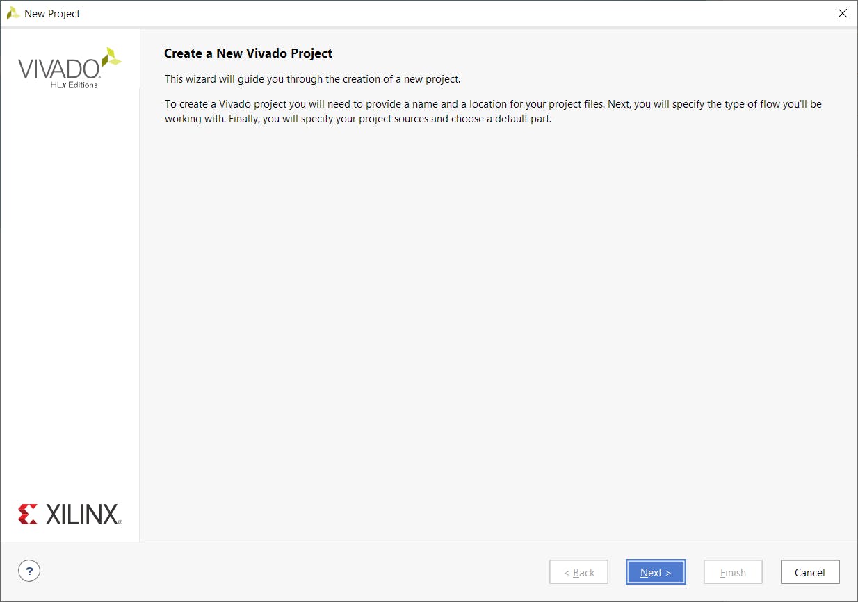
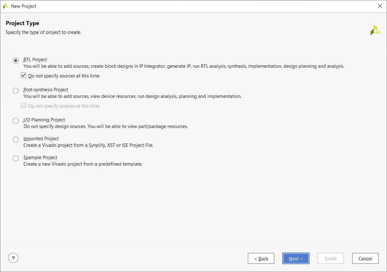
第 1 步- 打开 Vivado 并单击“创建项目”

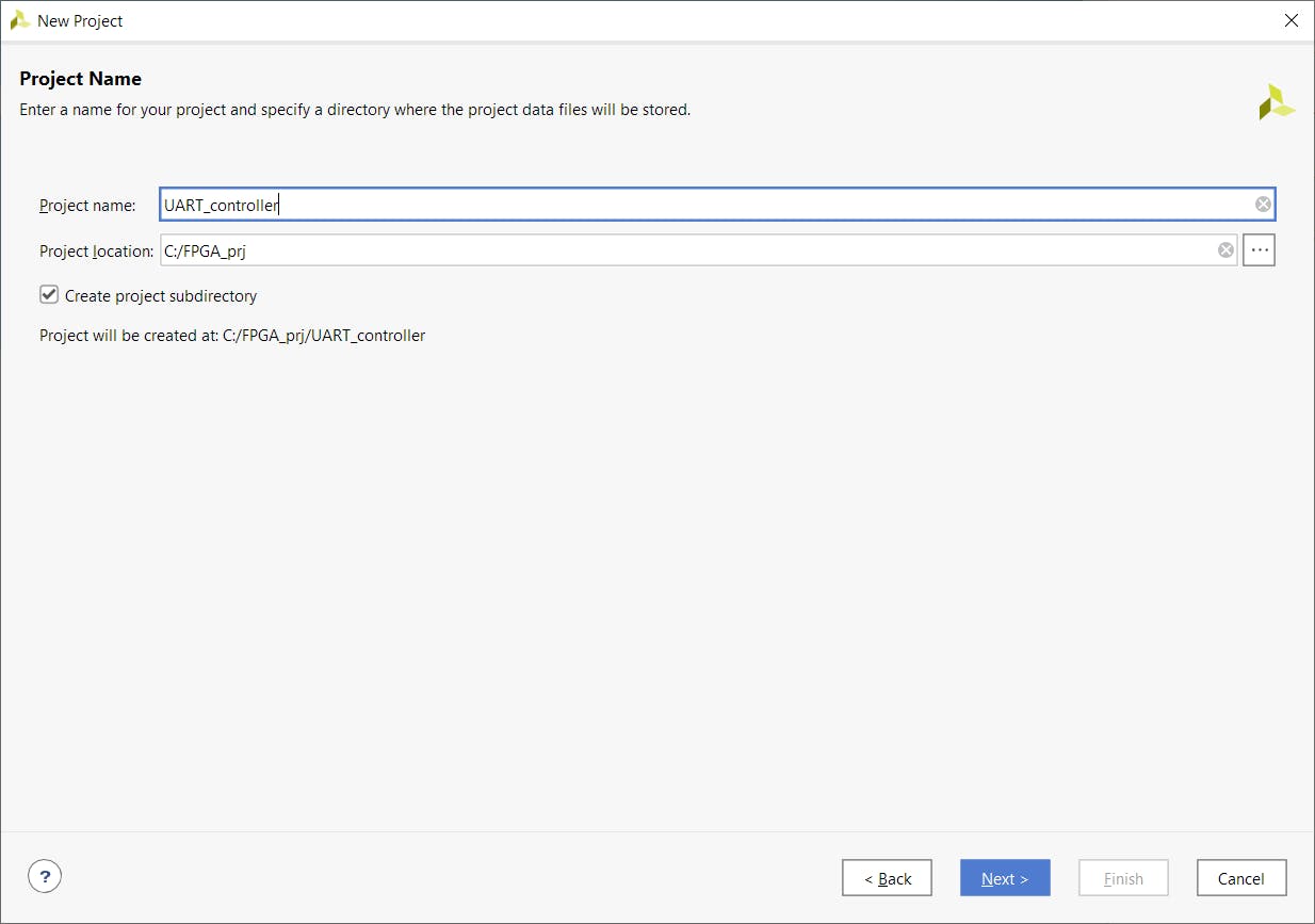
第 2 步- 为项目命名
第 3 步- 选择“RTL 项目”并留下勾号,稍后我们将添加文件
第 4 步- 选择电路板
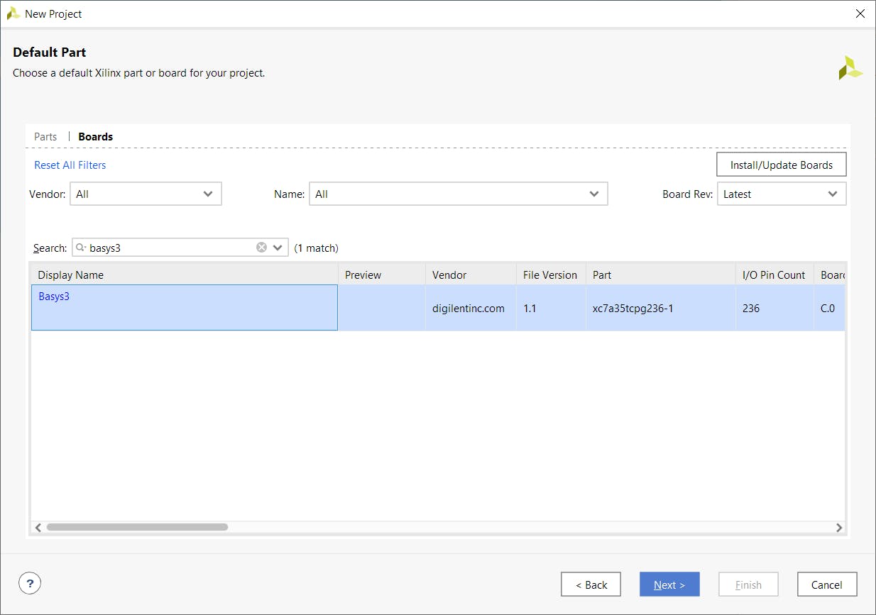
点击完成
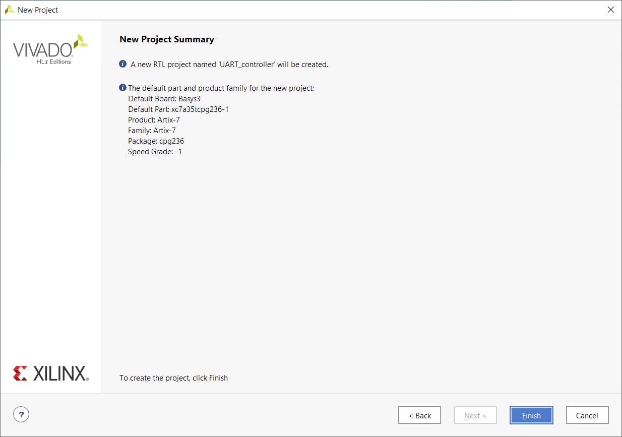
您将看到空项目。
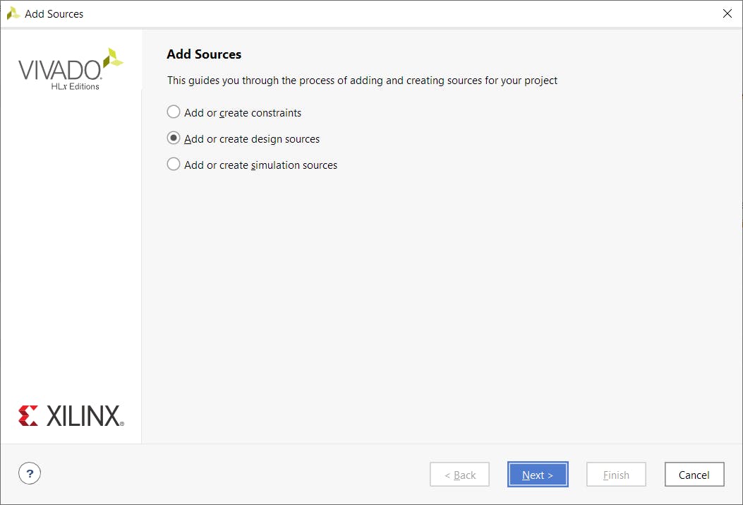
第 5 步- 单击“+”添加源文件
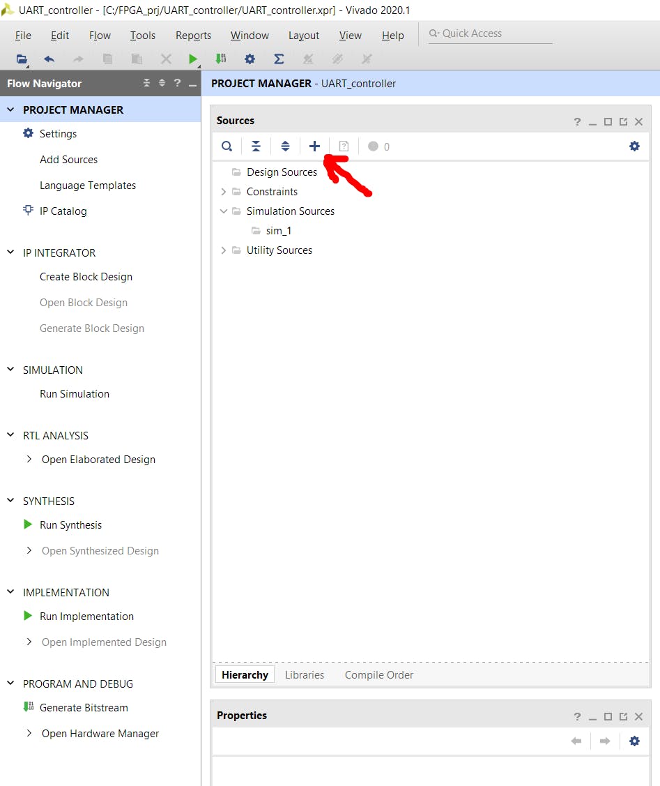
选择“添加或创建设计源”
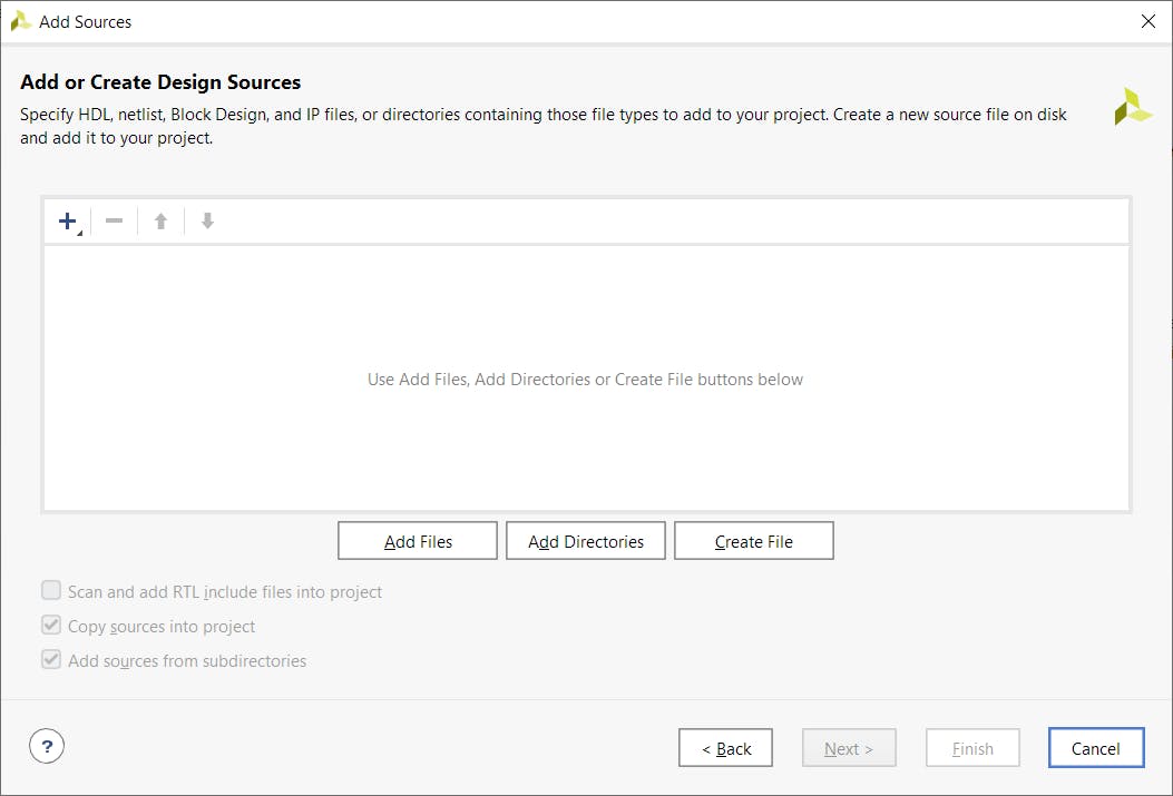
点击“添加文件”
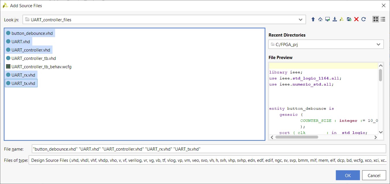
如图选择5个文件
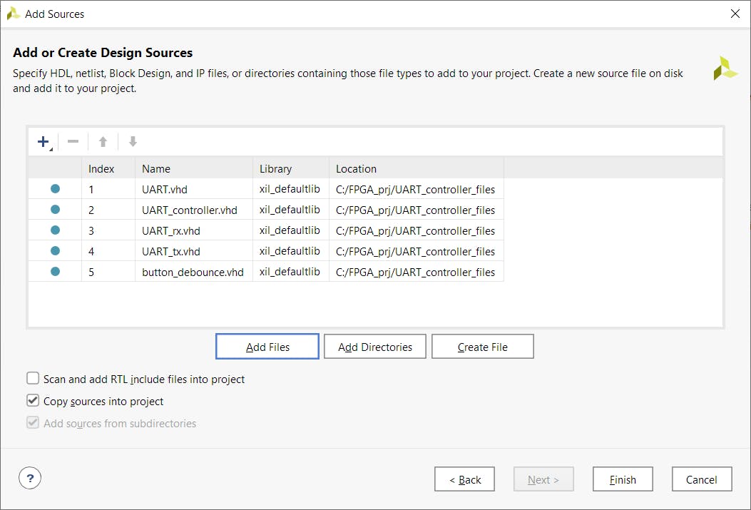
点击“完成”
第 6 步- 使用“添加或创建约束”和constraints.xdc文件重复第 5 步。
第 7 步- 使用“添加或创建模拟源”UART_controller_tb.vhd和UART_controller_tb_behav.wcfg文件重复第 5 步。
你已经完成了这些步骤,你应该看到这个:
设计模拟
为了开始模拟,您需要走这条路:
Flow Navigator => SIMULATION => 运行模拟 => 运行行为模拟
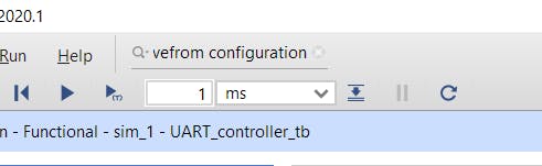
在模拟窗口中,您需要如图所示设置模拟时间,然后单击带有(T)子符号的“运行”按钮。
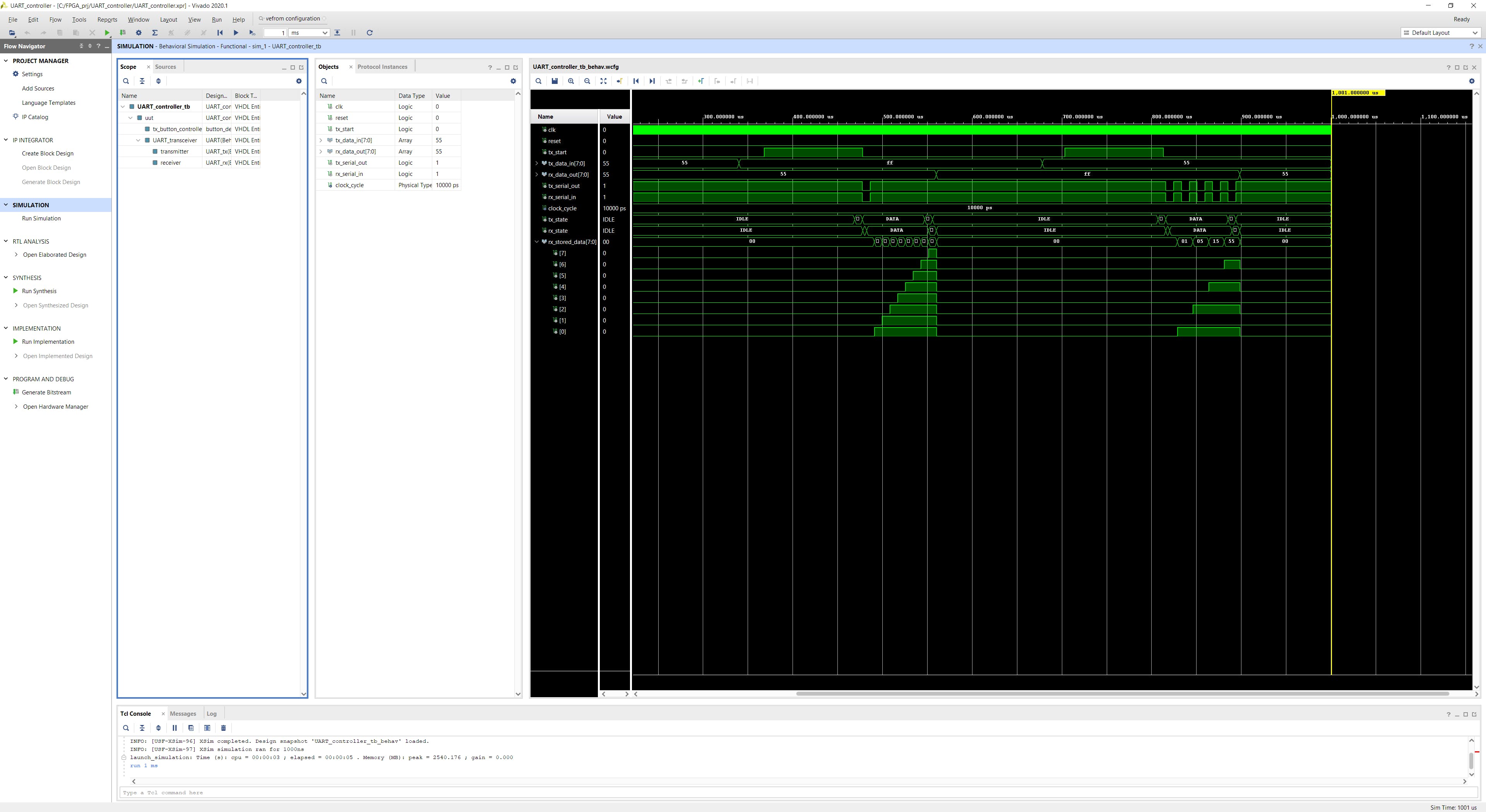
您应该能够看到如下图所示的模拟结果。您可以使用设置并选择其他信号以更好地了解设计。
综合、实现、比特流
完成模拟后,您可能需要构建项目。为此,您需要遵循以下路径:
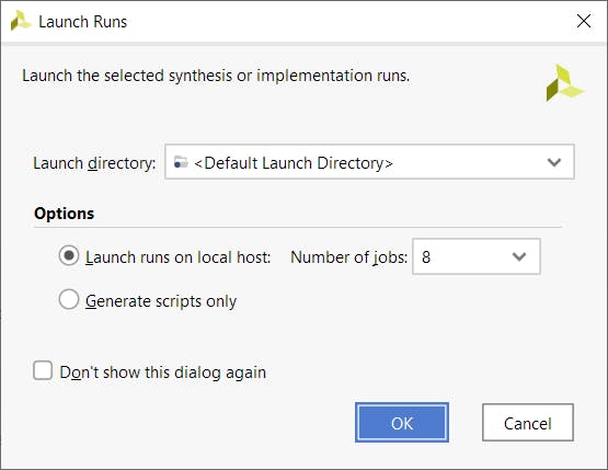
Flow Navigator => SYNTHESIS => 运行综合
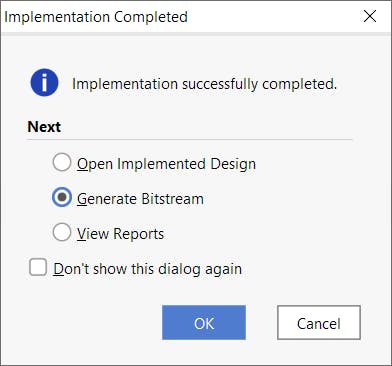
您将看到此窗口,单击“确定”。
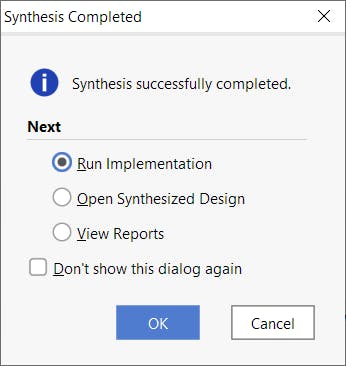
综合完成后,您可以直接从此窗口开始实施:
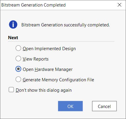
生成比特流的方式相同:
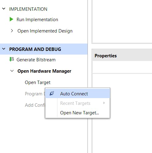
当比特流准备好后,您需要通过 USB 电缆将 Basys3 开发板连接到我们的计算机并打开开发板。之后,您需要打开硬件管理器:
单击“打开目标”并选择“自动连接”。
右键单击零件编号并选择“编程设备”。
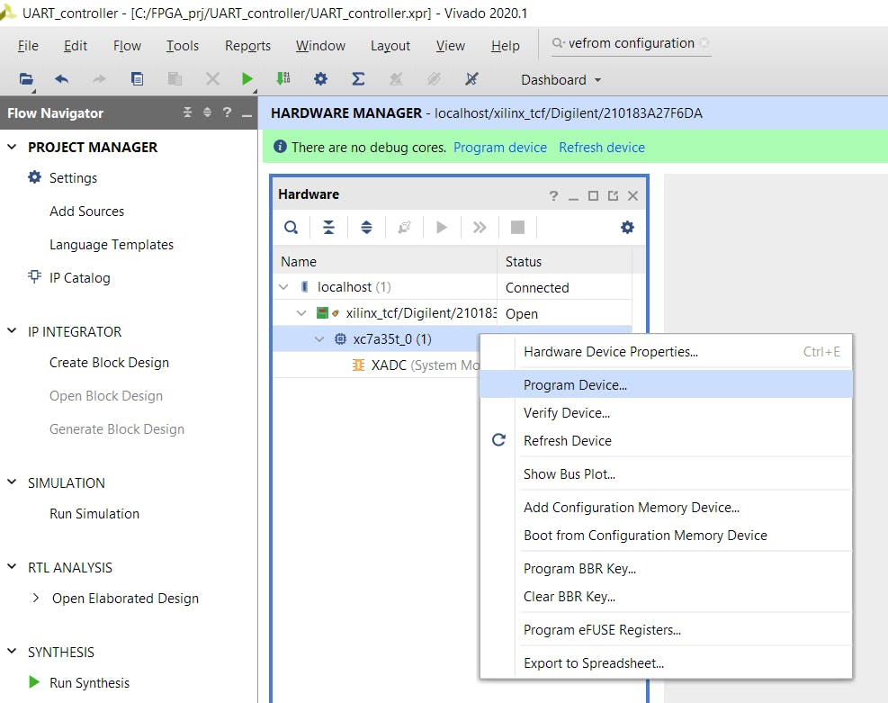
您将看到下面的窗口,只需单击“程序”。
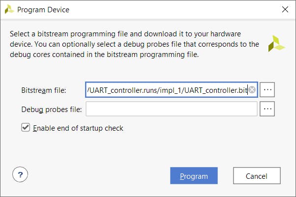
必须对芯片进行编程。最后一步是设置计算机终端。
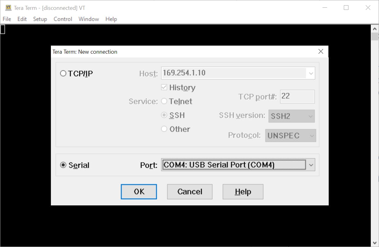
Tera 术语设置
打开 Tera Term 并选择“Serial”(在我的例子中是 COM4,但它可以是任何端口号)并单击 OK。
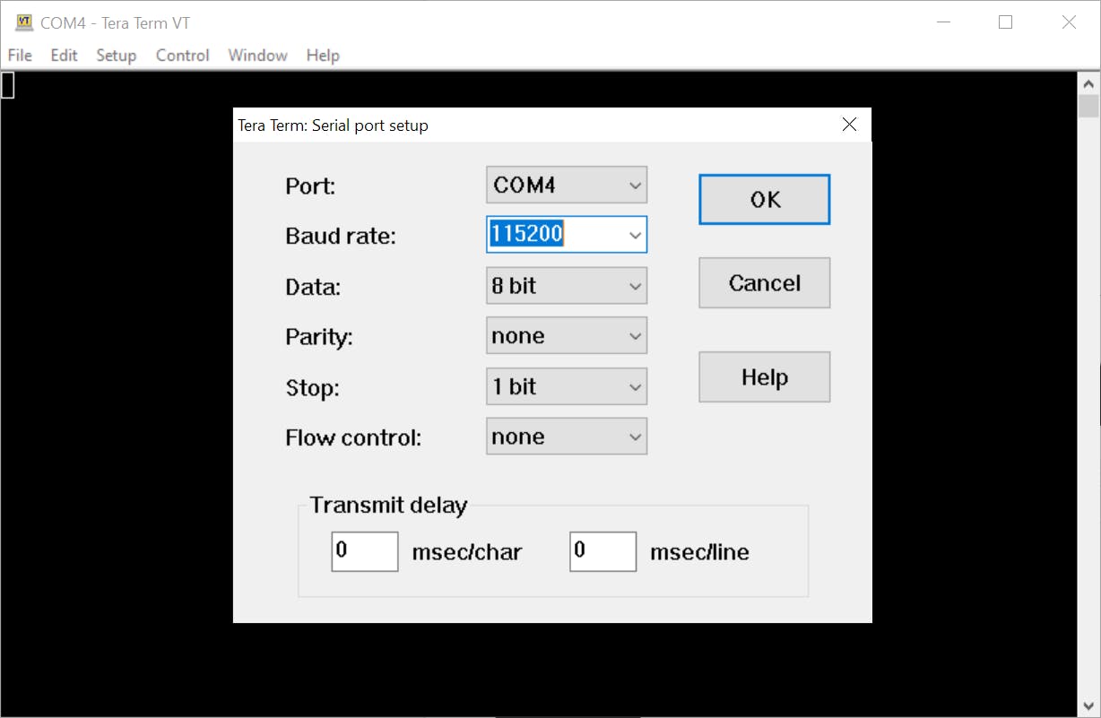
转到设置 => 串行端口...您将看到此窗口,如图所示设置
转到 Setup => Terminal... 并勾选“Local echo”,它可以让您查看您正在输入的内容。
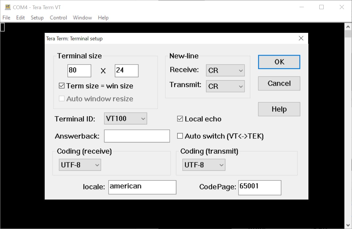
完毕!
怎么玩
为了查看您在键盘上按下的键的二进制表示,您需要检查板上的前 8 个 LED。
要将字节发送到终端,您需要使用前 8 个开关设置字节并按下中央按钮 (U18)。您将看到您在板上设置的字节的 ASCII 表示。
要重置设计,您需要按下顶部按钮 (T18)。
结论
这个项目远不是一个完成的专业项目,因为它没有很多重要的组件,例如:检查停止位、奇偶校验位、元稳定性防止、引脚缓冲区等。我想专注于主要设计:发送器和接收器的逻辑。
我希望这个项目是有帮助和有用的。
- 基于FPGA的波特率连续可调UART接口 10次下载
- Basys 3 Power Tree 14次下载
- TLC7524接口电路的VHDL程序与仿真免费下载 4次下载
- DAC0832接口电路的VHDL程序与仿真免费下载 7次下载
- 4个URAT VHDL程序与仿真的资料合集 6次下载
- BASYS 3开发板的电路原理图免费下载 22次下载
- 用于硬件UART和软件模拟UART的DSPBIOS设备驱动程序的实现详细概述 11次下载
- 基于Vivado 的Basys3开发板的解码教程 65次下载
- FPGA频率测量-基于XADC源码 11次下载
- SDRAM接口的VHDL设计方案 57次下载
- 通用异步串行接口的VHDL实用化设计 19次下载
- 通用异步串行接口的VHDL实用化设计 23次下载
- UART参考设计,带16byte缓冲 VHDL代码 xapp 33次下载
- UART 4 UART参考设计,Xilinx提供VHDL代码 113次下载
- 介绍Xilinx CPLD中配置UART的VHDL和Veri 17次下载
- 嵌入式系统串口UART接口为啥没有数据输出 530次阅读
- 图解UART与COM接口 1997次阅读
- 如何配置MAX78615+LMU用于UART通信 590次阅读
- 如何使用Basys3板创建一个简单的示波器 7495次阅读
- VK32系列新型多总线接口UART器件的原理及应用研究 1033次阅读
- Firefly-RK3128开发板UART接口介绍 2821次阅读
- digilentUSB转UART接口介绍 2005次阅读
- Firefly关于UART接口使用介绍 2484次阅读
- UART通信的工作原理及优缺点分析 1.4w次阅读
- 基于UART接口功能的实现设计 1411次阅读
- 基于FPGA芯片的UART接口电路设计 1830次阅读
- 实现了接口功能和性能验证自动化的UART&SPI接口验证工具设计 2975次阅读
- 电视uart接口干什么的 1.1w次阅读
- UART的收发数据操作介绍 1.3w次阅读
- uart接口介绍和认识 2.2w次阅读

 上传资料赚积分
下载排行
本周
- 1山景DSP芯片AP8248A2数据手册
- 1.06 MB | 532次下载 | 免费
- 2RK3399完整板原理图(支持平板,盒子VR)
- 3.28 MB | 339次下载 | 免费
- 3TC358743XBG评估板参考手册
- 1.36 MB | 330次下载 | 免费
- 4DFM软件使用教程
- 0.84 MB | 295次下载 | 免费
- 5元宇宙深度解析—未来的未来-风口还是泡沫
- 6.40 MB | 227次下载 | 免费
- 6迪文DGUS开发指南
- 31.67 MB | 194次下载 | 免费
- 7元宇宙底层硬件系列报告
- 13.42 MB | 182次下载 | 免费
- 8FP5207XR-G1中文应用手册
- 1.09 MB | 178次下载 | 免费
本月
- 1OrCAD10.5下载OrCAD10.5中文版软件
- 0.00 MB | 234315次下载 | 免费
- 2555集成电路应用800例(新编版)
- 0.00 MB | 33566次下载 | 免费
- 3接口电路图大全
- 未知 | 30323次下载 | 免费
- 4开关电源设计实例指南
- 未知 | 21549次下载 | 免费
- 5电气工程师手册免费下载(新编第二版pdf电子书)
- 0.00 MB | 15349次下载 | 免费
- 6数字电路基础pdf(下载)
- 未知 | 13750次下载 | 免费
- 7电子制作实例集锦 下载
- 未知 | 8113次下载 | 免费
- 8《LED驱动电路设计》 温德尔著
- 0.00 MB | 6656次下载 | 免费
总榜
- 1matlab软件下载入口
- 未知 | 935054次下载 | 免费
- 2protel99se软件下载(可英文版转中文版)
- 78.1 MB | 537798次下载 | 免费
- 3MATLAB 7.1 下载 (含软件介绍)
- 未知 | 420027次下载 | 免费
- 4OrCAD10.5下载OrCAD10.5中文版软件
- 0.00 MB | 234315次下载 | 免费
- 5Altium DXP2002下载入口
- 未知 | 233046次下载 | 免费
- 6电路仿真软件multisim 10.0免费下载
- 340992 | 191187次下载 | 免费
- 7十天学会AVR单片机与C语言视频教程 下载
- 158M | 183279次下载 | 免费
- 8proe5.0野火版下载(中文版免费下载)
- 未知 | 138040次下载 | 免费


 工商网监
工商网监
评论