 电子发烧友App


 创作
创作 发文章
发文章 发帖
发帖  提问
提问  发资料
发资料 发视频
发视频资料介绍
描述
微软的 Azure RTOS ThreadX 是开源的!我们想向您展示 ThreadX 的基础知识,以便您可以开始在您的 Arduino 项目中使用这个工业级 RTOS。
预计时间:设置:5 分钟;第 1 部分:5 分钟;第 2 部分:30 分钟;第 3 部分:15 分钟
估计成本:配备ATSAMD21 或 ATSAMD51芯片的设备 $
介绍
本教程将向您展示如何在 Azure RTOS ThreadX for Arduino 中使用多线程。您将从经典的 Blink 示例开始,并将其转换为 ThreadX 应用程序。
Azure RTOS:用于微控制器 (MCU) 上的嵌入式 IoT 应用程序的 Microsoft 开发套件。Azure RTOS不需要Azure即可运行。
Azure RTOS ThreadX:Azure RTOS 产品的一个组件。ThreadX是设计用于在 MCU 上运行的实时操作系统 (RTOS)。
Azure RTOS ThreadX for Arduino:Azure RTOS ThreadX 作为库到 Arduino 的端口。请访问GitHub 上的AzureRTOS-ThreadX-For-Arduino获取源代码。
涵盖的内容
在本教程结束时,您应该了解以下内容:
术语:内核、线程、线程控制块、优先级、抢占、抢占阈值
Actions :如何使用 ThreadX 实现单线程;如何使用 ThreadX 实现多线程
最终代码:在GitHub 上查看完整的 ThreadX 多线程 Blink 代码示例。
先决条件
- 安装Arduino IDE 1.8.x。
- 拥有使用ATSAMD21 或 ATSAMD51芯片的设备。查看此已验证板的列表。
以下是在 Windows 11、Arduino IDE 1.8.19、Arduino MKR WiFi 1010 和 Seeed Studio Wio 终端上运行的。
设置
预计时间: 5 分钟
步骤 1.打开 Arduino IDE。
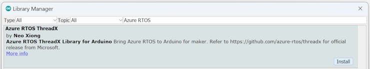
步骤 2.安装 Azure RTOS Arduino 库。
- 导航到工具 > 管理库...
- 搜索“Azure RTOS” 。
- 安装“Azure RTOS ThreadX” 。请务必安装最新版本。
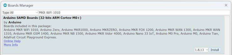
步骤 3.为您的设备安装板包。(本示例使用 Arduino MKR WiFi 1010。)
第 1 部分:运行 Arduino Blink 示例
在本节中,我们将运行传统的 Blink 示例以确认设备设置正确。
预计时间: 5 分钟
步骤 1.打开 Blink 示例。
- 导航到文件 > 示例 > 01.Basics 。
- 选择“闪烁” 。
第 2 步。连接您的设备。
- 将您的设备插入您的 PC。
- 导航到工具 > 板:... > Arduino SAMD 板(32 位 ARM Cortex-M0+)
- 选择“Arduino MKR WiFi 1010” 。
- 导航到工具 > 端口。
- 选择“<与设备关联的端口>” 。
步骤 3.运行示例。
- 在左上角,选择“上传”图标。验证将首先自动进行。
- 观察 LED 每 1 秒闪烁一次。
深潜
代码
// the setup function runs once when you press reset or power the board
void setup() {
  // initialize digital pin LED_BUILTIN as an output.
  pinMode(LED_BUILTIN, OUTPUT);
}

// the loop function runs over and over again forever
void loop() {
  digitalWrite(LED_BUILTIN, HIGH); // turn the LED on (HIGH is the voltage level)
  delay(1000);                     // wait for a second
  digitalWrite(LED_BUILTIN, LOW);  // turn the LED off by making the voltage LOW
  delay(1000);                     // wait for a second
}
到底是怎么回事?
Arduino 利用了两个核心功能:setup()和loop(). 一旦setup()完成,loop()就会在内部启动并运行程序的其余部分。因为不存在 RTOS,所以这段代码可以被认为是裸机编程。
有关更多信息,请参阅完整的 Arduino Blink示例。
第 2 部分:通过 ThreadX 转换 Blink 示例
在本节中,我们将使用 ThreadX 将裸机 Blink 示例转换为单线程 RTOS 版本。
预计时间: 30 分钟
步骤 1.保存示例。
- 导航到文件 > 另存为。
- 将草图另存为'Blink_ThreadX' 。
步骤 2. (1) 在文件顶部附近添加 Azure RTOS ThreadX 库头文件。tx_api.h将它放在评论之后,但在setup()功能之前。
/* (1) Add the Azure RTOS ThreadX library header file. */
#include
到底是怎么回事?
tx_api.h是您在 Arduino 中使用 ThreadX 时唯一需要包含的头文件。tx是 ThreadX 的缩写。API 中的所有函数都以tx. 所有常量和数据类型都以TX.
步骤 3. (2) 将内核入口函数添加tx_kernel_enter()到setup().
// the setup function runs once when you press reset or power the board
void setup() {
  // initialize digital pin LED_BUILTIN as an output.
  pinMode(LED_BUILTIN, OUTPUT);

  /* (2) Add the kernel entry function. */
  tx_kernel_enter();
}
到底是怎么回事?
内核是 RTOS 的核心组件。将其视为项目的首席协调员或物流总监。通过“进入”内核,RTOS 内核可以开始运行和管理您的嵌入式应用程序。
该程序永远不会从tx_kernel_enter(). 结果,应用程序将不会返回setup(),loop()也不会被调用。
重要提示:“对 tx_kernel_enter() 的调用不会返回,因此不要在其后进行任何处理。”
有关. _ _tx_kernel_enter()
Step 4. (3) 添加线程栈内存和线程控制块。将其放置在文件顶部附近之后#include 和之前setup()。
/* (3) Add the thread stack memory and thread control block. */
#define THREAD_STACK_SIZE 512

TX_THREAD thread_0;
UCHAR thread_0_stack[THREAD_STACK_SIZE];
到底是怎么回事?
线程是进程(即正在运行的应用程序)内的特定执行路径。线程与其他线程共享内存空间,但有自己分配的堆栈空间。我们将此堆栈大小定义为THREAD_STACK_SIZE字节并使用数组thread_0_stack来分配内存。有关线程堆栈区域的更多信息,请参阅Microsoft Learn 的 ThreadX 第 3 章:ThreadX 的功能组件。
线程控制块包含线程的特定数据。TX_THREAD是线程控制块的 ThreadX 数据类型。有关. _ _TX_THREAD
重要提示:“ThreadX 不使用术语任务。相反,使用更具描述性和现代性的名称线程。” 有关任务与线程的更多信息,请参阅Microsoft Learn 的 ThreadX 第 1 章:ThreadX 简介。
Step 5. (4) 定义线程的入口函数thread_0_entry()。将函数定义放在thread_0_stack数组之后和之前setup()。
/* (4) Define the thread's entry function. */
void thread_0_entry(ULONG thread_input)
{
  (VOID)thread_input;

  while(1)
  {
    /* Add thread logic to execute here. */
  }
}
到底是怎么回事?
线程的入口函数由内核调用,包含线程执行逻辑。通常,此函数将包含一个无限循环(即while(1)),它将在整个运行程序中执行。此函数的名称由用户确定。
步骤 6. (5) 将 LED 闪烁逻辑从loop()线程的入口函数中移出。替换delay(1000)为tx_thread_sleep(TX_TIMER_TICKS_PER_SECOND)。
void thread_0_entry(ULONG thread_input)
{
  (VOID)thread_input;

  while(1)
  {
    /* (5) Move the LED blink logic into the thread's entry function. */
    digitalWrite(LED_BUILTIN, HIGH);            // turn the LED on
    tx_thread_sleep(TX_TIMER_TICKS_PER_SECOND); // wait for a second
    digitalWrite(LED_BUILTIN, LOW);             // turn the LED off
    tx_thread_sleep(TX_TIMER_TICKS_PER_SECOND); // wait for a second
  }
}
// the loop function runs over and over again forever
void loop() {
  /* (5) Move the LED blink logic into the thread's entry function. */
  /* This will never be called. */
}
到底是怎么回事?
因为loop()将不再被调用,所以必须将闪烁逻辑移到新线程中。该delay()函数有局限性,因为我们稍后要暂停线程以允许其他线程执行,我们将使用 ThreadX 的tx_thread_sleep()函数来代替。此函数将计时器滴答作为其参数,而不是毫秒。
Step 7. (6) 添加应用程序的环境设置功能tx_application_define()。将此函数放置在 之后thread_0_entry()和之前setup()。
/* (6) Add the application's environment setup function. */
void tx_application_define(void *first_unused_memory)
{
  (VOID)first_unused_memory;

  /* Put system definition stuff in here, e.g. thread creates and other assorted
     create information. */
}
到底是怎么回事?
内核入口函数tx_kernel_enter()将调用该函数tx_application_define()来设置应用程序环境和系统资源。用户有责任使用为 RTOS 环境创建系统资源的逻辑来实现此功能。
有关. _ _tx_application_define()
第 8 步。(7) 使用 . 创建线程tx_thread_create()。将此函数调用添加到tx_application_define().
void tx_application_define(void *first_unused_memory)
{
  (VOID)first_unused_memory;

  /* Put system definition stuff in here, e.g. thread creates and other assorted
     create information. */

  /* (7) Create the thread. */
  tx_thread_create(&thread_0, "thread 0", thread_0_entry, 0,
    thread_0_stack, THREAD_STACK_SIZE,
    1, 1, TX_NO_TIME_SLICE, TX_AUTO_START);
}
到底是怎么回事?
tx_thread_create()创建具有指定参数的线程。此示例中使用的参数反映以下内容:
-
&thread_0: 指向定义的线程控制块的指针。(见步骤 4。) -
"thread_0": 线程名称(即,指向名称的指针)。 -
thread_0_entry:用户自定义线程入口函数。(见步骤 5。) -
0: 线程的入口输入。我们没有利用这个论点。 -
thread_0_stack: 指向线程堆栈开始的指针。(见步骤 4。) -
THREAD_STACK_SIZE:线程堆栈的大小(以字节为单位)。(见步骤 4。) -
1: 线程的优先级。 -
1:线程的抢占阈值。 -
TX_NO_TIME_SLICE: 时间片被禁用。 -
TX_AUTO_START: 线程自动启动。
线程的优先级有助于线程调度程序确定接下来要执行的线程。一些线程可能对执行更为关键,因此相对于其他线程被赋予更高的优先级。ThreadX 有 32 个默认优先级,从 0 到 31,0 为最高优先级,31 为最低优先级。
抢占是指停止现有线程的执行,以便可以运行更高优先级。调度程序控制这一点,当中断线程完成时,执行返回到暂停的线程。
抢占阈值是 ThreadX 独有的。只有高于此阈值的优先级才能抢占线程。
有关线程执行、线程优先级、线程调度和线程抢占的更多信息,请参阅Microsoft Learn 的 ThreadX 第 3 章:ThreadX 的功能组件。
步骤 9.使用 Azure RTOS ThreadX 运行 Blink 示例。
按照第 2 步。连接您的设备和第 3 步。运行第 1 部分中的示例:运行 Arduino Blink 示例。
深潜
代码
/* (1) Add the Azure RTOS ThreadX library header file. */
#include
注意:Arduino Blink 格式和单行样式注释//已转换为 ThreadX 格式和多行样式/* */。
到底是怎么回事?
setup()上面的代码演示了如何用Azure RTOS ThreadX替换 Arduino 裸机单线程方法。loop()
之前的裸机代码流程是:
-
setup()->loop()-> 无限循环闪烁逻辑。
ThreadX 新的代码流程是:
-
setup()->tx_kernel_enter()->tx_application_define()->thread_0_entry()-> 无限循环 Blink 逻辑。
尽管这种方法仍然保持相同的单线程功能,但现在可以根据需要添加额外的线程。第 3 部分将演示如何执行此操作。
第 3 部分:通过 ThreadX 将多线程应用到 Blink 示例
在本节中,我们将使用单线程 ThreadX Blink 代码创建一个多线程版本,该版本也可以读取串行输入。
预计时间: 15 分钟
步骤 1.保存示例。
- 导航到文件 > 另存为。
- 将草图另存为'Blink_SerialRead_ThreadX' 。
步骤 2. (8) 添加线程堆栈内存和线程控制块以再增加一个线程。
/* (3)(8) Add the thread stack memory and thread control block. */
#define THREAD_STACK_SIZE 512

TX_THREAD thread_0;
TX_THREAD thread_1;

UCHAR thread_0_stack[THREAD_STACK_SIZE];
UCHAR thread_1_stack[THREAD_STACK_SIZE];
到底是怎么回事?
此操作模仿第 2 部分:第 4 步。对于要添加的每个线程,您需要分配其堆栈内存并声明其线程控制块。 TX_THREAD
Step 3. (9) 定义新线程的入口函数thread_1_entry()。将函数定义放在 之后thread_0_entry()和之前tx_application_define()。
/* (9) Define the thread's entry function. */
void thread_1_entry(ULONG thread_input)
{
  (VOID)thread_input;

  while(1)
  {
    /* Add thread logic to execute here. */
  }
}
到底是怎么回事?
此操作模仿第 2 部分:第 5 步。每个线程都需要一个用户定义的入口函数来执行线程逻辑。
Step 4. (10) 将串行读取逻辑添加到线程的入口函数中。
void thread_1_entry(ULONG thread_input)
{
(VOID)thread_input;
/* (10) Add serial read logic to the thread's entry function. */
Serial.begin(115200);
while(1)
{
if (Serial.available() > 0)
{
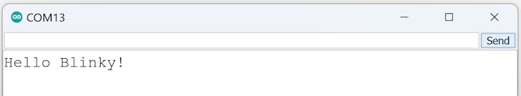
char byte_read = Serial.read();
Serial.print(byte_read);
}
}
}
到底是怎么回事?
串行读取逻辑从串行输入接收字节并将它们打印到串行监视器。请注意,此逻辑放在 中while(1),但串行初始化Serial.begin()函数没有。因为初始化只需要发生一次,所以放在前面while(1)。或者,它可以放在setup()之前tx_kernel_enter()。
第 5 步。(11) 使用 . 创建新线程tx_thread_create()。在tx_application_define()创建thread_0.
void tx_application_define(void *first_unused_memory)
{
  (VOID)first_unused_memory;

  /* Put system definition stuff in here, e.g. thread creates and other assorted
     create information.  */

  /* (7)(11) Create the thread. */
  tx_thread_create(&thread_0, "thread 0", thread_0_entry, 0,
    thread_0_stack, THREAD_STACK_SIZE,
    1, 1, TX_NO_TIME_SLICE, TX_AUTO_START);

  tx_thread_create(&thread_1, "thread 1", thread_1_entry, 0,
    thread_1_stack, THREAD_STACK_SIZE,
    4, 4, TX_NO_TIME_SLICE, TX_AUTO_START);
}
到底是怎么回事?
此操作模仿第 2部分:第8步。 在所使用的论点中发现了差异。注意命名如何改变以反映: thread_1
-
&thread_1: 指向定义的线程控制块的指针。 -
"thread_1": 线程名称(即,指向名称的指针)。 -
thread_1_entry:用户自定义线程入口函数。 -
thread_1_stack: 指向线程堆栈开始的指针。
另一个改变的参数集是优先级和抢占阈值:
-
4: 线程的优先级。 -
4:线程的抢占阈值。
因为4的优先级低于1 ,thread_0所以将首先执行,并且只有在它挂起时(tx_thread_sleep()),调度程序才会执行行中的下一个线程(thread_1)。一旦thread_0完成暂停,调度程序将抢占thread_1并返回执行thread_0。
保持不变的论点是:
-
0: 线程的入口输入。 -
THREAD_STACK_SIZE:线程堆栈的大小(以字节为单位)。 -
TX_NO_TIME_SLICE: 时间片被禁用。 -
TX_AUTO_START: 线程自动启动。
步骤 6.使用 Azure RTOS ThreadX 运行多线程 Blink 示例。
- 按照第 2 步。连接您的设备和第 3 步。运行第 1 部分中的示例:运行 Arduino Blink 示例。
- 观察 LED 每 1 秒闪烁一次。
- 导航到工具 > SerialMonitor 。
- 输入你好闪烁!进入串行输入线。
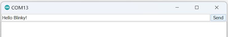
- 选择“发送” 。
深潜
代码
/* (1) Add the Azure RTOS ThreadX library header file. */
#include
注意:Arduino Blink 格式和单行样式注释//已转换为 ThreadX 格式和多行样式/* */。
到底是怎么回事?
上面的代码演示了如何使用 Azure RTOS ThreadX 向 Arduino 应用程序添加额外的线程。一个线程使 LED 闪烁,而另一个线程接收串行输入并将其打印到串行监视器。线程对于同时且彼此独立地执行不同的任务非常有帮助。
尽管本教程中没有演示,但线程也可以通过同步和相互通信。当程序需要随时接收传入数据但也需要对其进行处理时,这可能很有用。这两个任务可以分成两个线程。
我们希望在未来的 Azure RTOS ThreadX for Arduino 教程中介绍这些和其他概念。敬请关注!
- 适用于Arduino的Adafruit NeoPixel Shield 0次下载
- 适用于Arduino YUN、UNO和Nano的DIN导轨安装 0次下载
- 适用于PC的ARDUINO控制游戏手柄(有线) 1次下载
- 适用于Azure Sphere的WS2812B LED灯带驱动器 0次下载
- 适用于ESP32的AWS IoT Arduino库 1次下载
- 适用于Arduino Uno板的简单计时器 0次下载
- DB459_适用于 STM32Cube 的 STM32L4 系列和 STM32L4+ 系列 Azure® RTOS 软件扩展 0次下载
- 适用于PC和Android的Arduino游戏控制器 0次下载
- 首款适用于Arduino的蓝牙家庭自动化扩展板 12次下载
- ThreadX(三)------线程thread 8次下载
- Azure RTOS NetX Duo嵌入式TCP/IP网络堆栈 13次下载
- 高性能嵌入式堆栈Azure PTOS USBX概述 9次下载
- 适用于MPLAB工具设计的多条忠告 7次下载
- 嵌入式RTOS ThreadX 用户指南手册ver.4.0c 33次下载
- 适用于Microsoft_Azure的NetApp_ONTAP_ 0次下载
- RTOS中的线程、进程和协程详解 848次阅读
- 使用MM32F3270基于Azure RTOS定时器组的应用 1205次阅读
- 使用MM32F3270基于Azure RTOS动态内存管理的应用 554次阅读
- 使用MM32F3270基于Azure RTOS信号量的应用 546次阅读
- 如何将ThreadX移植到STM32H7平台 1354次阅读
- 如何将ThreadX移植到STM32平台 1115次阅读
- 一款适用于红蓝对抗的演练工具Goblin介绍 695次阅读
- RTOS多线程必须要MMU才行? 1775次阅读
- 如何使用Tracealyzer的流模式来跟踪ThreadX应用 1048次阅读
- Azure Kinect Senser DK套件简介 2649次阅读
- 如何编写适用于Go项目的Makefile 1821次阅读
- 基于一种适用于SSL产品的LED控制电路设计 907次阅读
- Super Sabre电源连接器系统,适用于大电流应用 730次阅读
- 主打嵌入式应用的中高阶RTOS 5375次阅读
- 适用于RS232串口的温度检测电路 2428次阅读

 上传资料赚积分
下载排行
本周
- 1山景DSP芯片AP8248A2数据手册
- 1.06 MB | 532次下载 | 免费
- 2RK3399完整板原理图(支持平板,盒子VR)
- 3.28 MB | 339次下载 | 免费
- 3TC358743XBG评估板参考手册
- 1.36 MB | 330次下载 | 免费
- 4DFM软件使用教程
- 0.84 MB | 295次下载 | 免费
- 5元宇宙深度解析—未来的未来-风口还是泡沫
- 6.40 MB | 227次下载 | 免费
- 6迪文DGUS开发指南
- 31.67 MB | 194次下载 | 免费
- 7元宇宙底层硬件系列报告
- 13.42 MB | 182次下载 | 免费
- 8FP5207XR-G1中文应用手册
- 1.09 MB | 178次下载 | 免费
本月
- 1OrCAD10.5下载OrCAD10.5中文版软件
- 0.00 MB | 234315次下载 | 免费
- 2555集成电路应用800例(新编版)
- 0.00 MB | 33566次下载 | 免费
- 3接口电路图大全
- 未知 | 30323次下载 | 免费
- 4开关电源设计实例指南
- 未知 | 21549次下载 | 免费
- 5电气工程师手册免费下载(新编第二版pdf电子书)
- 0.00 MB | 15349次下载 | 免费
- 6数字电路基础pdf(下载)
- 未知 | 13750次下载 | 免费
- 7电子制作实例集锦 下载
- 未知 | 8113次下载 | 免费
- 8《LED驱动电路设计》 温德尔著
- 0.00 MB | 6656次下载 | 免费
总榜
- 1matlab软件下载入口
- 未知 | 935054次下载 | 免费
- 2protel99se软件下载(可英文版转中文版)
- 78.1 MB | 537798次下载 | 免费
- 3MATLAB 7.1 下载 (含软件介绍)
- 未知 | 420027次下载 | 免费
- 4OrCAD10.5下载OrCAD10.5中文版软件
- 0.00 MB | 234315次下载 | 免费
- 5Altium DXP2002下载入口
- 未知 | 233046次下载 | 免费
- 6电路仿真软件multisim 10.0免费下载
- 340992 | 191187次下载 | 免费
- 7十天学会AVR单片机与C语言视频教程 下载
- 158M | 183279次下载 | 免费
- 8proe5.0野火版下载(中文版免费下载)
- 未知 | 138040次下载 | 免费


 工商网监
工商网监
评论