 智能电表的电源设计

Designers of power supplies for smart meters are faced with a range of issues. Not only do they need to take account of typical concerns such as energy efficiency, but also issues such as fraud and correct operation if the electrical supply fails.
The ability to run from low power levels is important. Only smart electricity meters have the luxury to have a grid power source and, even in this case, consumption must be minimized as the power to run the devices comes from the utility and not from the customer. Gas and water meters on the other hand need to be able to run from a battery, and guarantee a lifetime of ten years or more. This puts severe constraints on the efficiency of the power converter as well as the remaining meter electronics.
At the same time, these new types of meters need to be able to support 32-bit microprocessors and larger memory sizes so that they can provide cryptographic features, as well as more fine-grained usage measurements and data updates via wireless communications. If external electrical power fails, the meter needs to be able to send notifications to the utility, demanding the use of backup energy strategies.
Tampering is one key problem that smart meter designers have to face. One method used on electricity meters is to disrupt the measurements taken by current transformers that are used to measure alternating current (AC). As a transformer, this sensor has a primary winding, a magnetic core, and a secondary winding. The AC flowing in the primary produces an AC in the secondary, which can be measured by the meter using a shunt resistor.
The transformer used for current sensing can, with relative ease, be saturated using strong rare-earth metal magnets, preventing the meter from sensing the change in current. As a result, the transformers are now often shielded. However, would-be fraudsters may still try to tamper with the meter and, without realizing it, damage the power supply circuitry.
Many switched-mode power supplies used small ferrite-core transformers that are inexpensive and efficient, but also susceptible to strong magnetic fields such as those generated by rare-earth magnets held a few centimeters away. Saturating the transformer core often leads to overcurrent situations that can cause the MOSFET in the switching power supply to overload destructively. At this point, the meter will probably shut down until the power supply is replaced.
One way to avoid the problem is to use a relay to detect the magnetic field and disconnect the load, which will generally be the supply to the consumer’s premises, before the MOSFET can be damaged. Alternatively, a power supply design that incorporates protection features in the core circuitry can be used.
The LinkSwitch-XT family of devices from Power Integrations has protection against overcurrent built in.
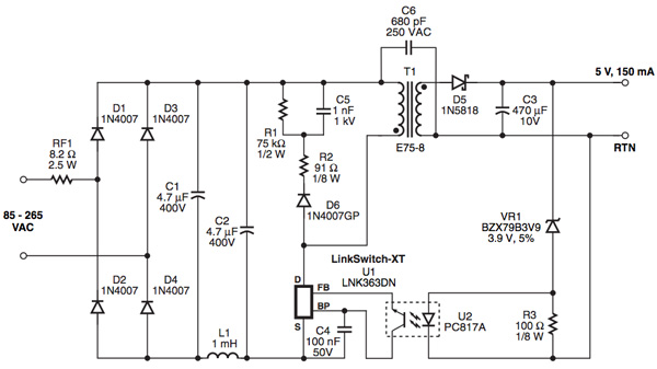
In the circuit shown in Figure 1, the transformer has been designed to provide sufficient inductance for the power supply to deliver the required power even if its core has been saturated. In the circuit, the four diodes D1-D4 are used to rectify the AC mains input. Together with capacitors C1 and C2, inductor L1 is part of a pi filter that is used to reduce differential-mode conducted electromagnetic interference (EMI). The power converter uses pulse skipping to provide power to the meter’s circuitry. At the start of each cycle, the LinkSwitch-XT samples the feedback-pin FB. If the current into this pin exceeds 49 µA, the switch is disabled for that cycle. If it is below the threshold, the MOSFET is switched on for the next power cycle.
The 1.1 V across the LED in U1, which is used to provide feedback control to the switching logic, and the Zener diode VR1 (3.9 V) sums to the required output voltage, in this case 5 V.
If the transformer becomes saturated, fast current limiting acts to protect the internal MOSFET of the LinkSwitch-XT device. However, while current limiting is in action, the output drops out of regulation and the meter will most likely stop. If constant operation during attempted tampering is required, an option is to shield the power supply’s transformer or to replace the ferrite with a high-reluctance powdered-iron material with a distributed air gap, providing some of the advantages of an air-core transformer without the efficiency losses. The powdered-iron material has a much higher saturation flux density than ferrite.
The Altair900 from STMicroelectronics also provides overcurrent protection against transformer saturation but uses a novel primary-sensing design to minimize the number of external components. The design puts a 900 V avalanche-ruggedized power switch and low-voltage pulse width modulation (PWM) controller into a single package and is supported by an evaluation board to make it easy to prototype systems.
The device is capable of providing constant output voltage using all primary sensing feedback. This eliminates the need for the opto-coupler used by other solutions, or a secondary voltage reference and current sensor. Even without these, it maintains accurate regulation. Also, it is possible to set the maximum deliverable output current, therefore increasing the end product's safety and reliability during fault events.
The switcher uses quasi-resonant operation with the help of a transformer demagnetization sensing input that turns on the power section. The same input also serves the output voltage monitor. To provide higher efficiency with very light loads, the device enters burst-mode operation. In between, it enters valley-skipping mode, only activating every few cycles.
Although an auxiliary winding is required in the transformer to correctly perform either constant-voltage or constant-current regulation, the IC is able to power itself directly from the rectified mains. This is useful especially during constant-current regulation, where the flyback voltage generated by the winding drops below the under-voltage lockout threshold. However, if ultra-low, no-load input consumption is required to comply with the most stringent energy-saving recommendations, then the device needs to be powered using the auxiliary winding.
An alternative architecture is to first provide an unregulated, low-voltage DC isolated supply that is then used to feed a high-efficiency converter. This reduces the isolation burden on the power regulator and provides some optimizations for use with measurement circuitry that only operates intermittently, which is typical for smart meters, as they will only wake periodically to take samples. The focus on light-load conditions helps improve overall efficiency. The Texas Instruments TPS54061 is an example of a high-efficiency converter with specialized features designed to support ultra-light load conditions. The low-side MOSFET used by the converter emulates a diode when the inductor current reaches zero.
The TPS54061 is a 60 V, 200 mA step-down/buck regulator with both integrated high- and low-side MOSFETs. The device employs a constant-frequency, current-mode control strategy to reduce output capacitance and to simplify the selection of external components. The switching frequency of 50 kHz to 1.1 MHz allows relatively small passive components to be used for the output filter. The switching frequency is programmed using a resistor to ground on the clock pin.
Designed specifically for light loads, the TPS54061 does not employ pulse skipping, and as a fixed-frequency controller has predictable output voltage ripple and noise under operating conditions. In terms of overall size, the optimum way to use the controller is to operate in discontinuous conduction mode (DCM), as this keeps passive components such as inductors small. The converter stays stable with ceramic output capacitors or low-cost aluminum electrolytics.
Gas and water meters place stringent demands on efficiency and use ultra-low-energy sleep modes to improve battery lifetime. For applications such as these, TI designed the TPS65290, a power-management IC that can operate over a wide range of system load conditions ranging from fractions of a microamp to a few hundred milliamps. The device operates over a wide 2.2 V to 5 V input-voltage range and incorporates a very-low quiescent current, always-on power supply, a 500 mA buck/boost converter, a 150 mA low dropout regulator, and eight power-distribution switches to provide a high degree of power control to meter electronics. One power switch can maintain the MCU in its sleep state, but cut power to analog sensors while they are not being used.
The buck-boost converter can work in either PWM or pulse frequency modulation (PFM) modes, the latter being used for very light loads. The device can be configured to work in only PWM mode if output ripple is an issue.
In electricity meters, if the external power fails, the meter runs the risk of failing as well. There is also the risk that the battery in a gas or water meter may fail early. Therefore, a backup energy source is needed. Although one option is to use a rechargeable battery, this necessitates the use of a charging circuit to maintain the battery at peak charge for use only in comparatively rare situations. Furthermore, the key requirement is for an instantaneously available backup source that will work at the low temperatures needed for outdoor units. The meter can then immediately transmit status information to the remote hub that collects usage data and alerts.
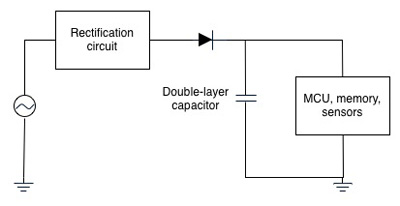
An effective alternative to a battery is to use a double-layer capacitor or ‘supercapacitor’. This is relatively straightforward to integrate into a circuit because it has the ability to store enough energy to maintain the basic functions of a smart meter temporarily without demanding complex switching logic.
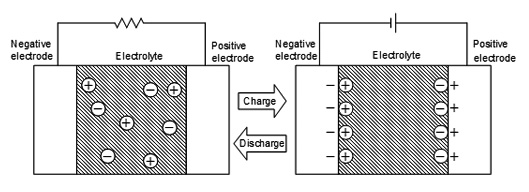
In contrast to conventional capacitors, which rely purely on electron movements, double-layer capacitors use the movement of ions within a thin membrane. When a voltage is applied across the two electrodes, ions in the electrolyte of the capacitor move to try to negate the charge on the electrodes. Positively charged ions move to the negative electrode and vice versa. This forms a positively and a negatively charged layer within the electrolyte, forming the double layer that gives the capacitor its name. When the voltage is removed, the ions move away from the electrodes, discharging the stored energy.
Nichicon's UK Series was developed to meet the needs of smart meter manufacturers who require capacitors with lower resistance and the ability to operate in low temperatures.
Nichicon reduced resistance over conventional electrodes by approximately 50 percent by optimizing parameters such as the pore size of the activated charcoal used as the capacitor matrix, and the thickness of the electrodes. For the electrolyte solution, Nichicon used an alternative to acetonitrile, which is used by many companies around the world as a solvent because it offers reduced resistance due to its low viscosity, but also can give off toxic gases if burned. Nichicon adopted a propylene carbonate-based solution. For low-temperature operation, the UK Series is guaranteed to -40°C and provides capacitance up to 27 F.
The Panasonic RG series of double-layer capacitors is another option for providing a temporary backup power source, with capacitance up to 1 F.
Although smart utility meters have stringent demands, solutions exist to deal with problems such as tampering, and provide tolerance to power failures so that the meter can at least signal to the utility firm that it has encountered a problem and needs maintenance.
声明:本文内容及配图由入驻作者撰写或者入驻合作网站授权转载。文章观点仅代表作者本人,不代表电子发烧友网立场。文章及其配图仅供工程师学习之用,如有内容侵权或者其他违规问题,请联系本站处理。
举报投诉
发布评论请先 登录
相关推荐
热点推荐
智能电表想进美国?先过UL认证这关!
抢占先机,从东鸿UL电表开始 美国智能电表市场正处于渗透率快速提升的黄金期,政策推动与需求升级共同构筑了千亿级市场空间,而UL认证则是进入这一市场的“必备门票”。东鸿电子凭借对国际标准的深刻理解
揭秘MID电表:它和普通电表有啥不同?
“MID电表”?“普通电表”?在选购或谈论智能电表时,这两个词大家可能经常听到,但很多人其实并不清楚它们之间到底有哪些关键区别,以及为什么在某些场景下MID
物联网智能电表平台:所有电表数据,集中到一个系统管
物联网智能电表平台,不是简单的“抄表软件”,而是一套集数据采集、远程控制、计费管理、异常预警、财务结算于一体的云端管理系统。它把分散在各房间、各楼栋的智能电表连接起来,实现“一个平台看

霍尔电流传感器在智能电表中的应用
霍尔电流传感器:智能电表的"隐形守护者",如何重塑用电安全与精准计量? 在能源数字化与物联网技术飞速发展的今天,智能电表已从单纯的电量统计工具,演变为家庭与工业能源管理的核心枢纽。而在
一触即达:CCLink IE遇见Modbus RTU,解锁智能电表“数据超车道”
在工业现场,工程师们常常会遇到这样的场景:新部署的智能电表需要接入既有系统,却因协议差异卡在通信环节。CCLINKIE总线与Modbus RTU网关协议的兼容性问题,正是许多自动化项目中的典型技术痛
发表于 06-23 13:59
破解跨协议难题:CC\\-Link IE转EtherNet/IP让智能电表数据畅通无阻
各位同行们,是不是经常遇到这样的场景:厂里新上的智能电表用的是一套协议,原有的老设备又是另一套\"方言\",想让它们愉快地\"交流\"数据,简直让人头
发表于 06-17 15:23
电表“双语”教学:PEOFINET转CCLINKIE的神仙联动
家人们谁懂啊!在工业自动化领域,智能电表就像一个信息宝库,可要是协议不匹配,就如同宝藏被上了一把锁,怎么都打不开。今天就来聊聊PROFINET转CCLINK IE在连接智能电表方面的神
发表于 06-06 14:24

电力改造项目推荐哪款电表?物联网电表的优势
在电力改造中,物联网电表是一个非常值得推荐的选择。物联网电表又称智能电表,是一种集成了现代通信技术、测量技术和数据处理技术的先进计量装置。它能够实时监测、记录并传输用户的用电数据至电网


 工商网监
工商网监
评论