 刹车灯(英文),Pulsing Third Brake Light

刹车灯(英文),Pulsing Third Brake Light
关键字:刹车灯(英文)
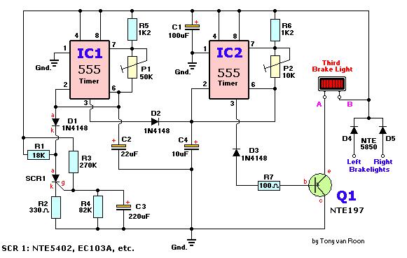
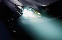
Circuit dijagram
Parts
IC1,IC2 = 555 Timer, RS #276-1723
SCR1 = NTE/ECG5402, RS #276-1067, EC103A, MCR104, etc.
Q1 = NTE/ECG197, SK3083, TIP125, or equivalent
D1,D2,D3 = 1N4148, 1N914, NTE/ECG519, RS #276-1122
D4,D5 = 1N5400, NTE/ECG5850, RS #276-1141, or equivalent
R1 = 18K
R2 = 330 ohm (RS #271-1315)
R3 = 270K
R4 = 82K
R5,R6 = 1K2
R8 = 100 ohm (RS# 271-1311)
P1 = 50K, 10-turn
P2 = 10K, 10-turn
C1 = 100µF/16V (RS# 272-1016)
C2 = 22µF/16V (RS# 272-1014)
C3 = 220µF/16V (RS# 272-1017)
C4 = 10µF/16V (RS# 272-1013)
Q1 is a PNP Silicon Audio Power Out/Medium Power Switch Transistor, 7A, with a TO-220 case. As long as you have a transistor which is close it will work fine. The SCR is a 100vrm, 0.8A, sensitive gate with a TO-92 case. Diodes D1, D2 and D3 are standard small signal diodes. Power diodes D4 and D5 are the 6A, 50prv types, cathode case. The 60vrm type will work as well. I used for IC1 & IC2 the LM555 type. P1 controls the 'on' and pulse-duration, P2 controls the pulse-timing.
Applying the Brakes:
When you first press the brakes, this circuit will turn on your 3rd brake light via the main brake lights. After about a second a series of short strobe pulses occur. The number of pulses range from approximately 1 to 10, depending on the setting of P1/P2 and when the brake pedal was applied last. After the pulses have been applied the third brake light assumes normal operation. The prototype was set for five flashes which seemed more than enough. Two days later I re-adjusted the trimmer potentiometers for 4 flashes--1/2 second pause--4 flashes. Looks pretty cool!
When you first press the brakes, this circuit will turn on your 3rd brake light via the main brake lights. After about a second a series of short strobe pulses occur. The number of pulses range from approximately 1 to 10, depending on the setting of P1/P2 and when the brake pedal was applied last. After the pulses have been applied the third brake light assumes normal operation. The prototype was set for five flashes which seemed more than enough. Two days later I re-adjusted the trimmer potentiometers for 4 flashes--1/2 second pause--4 flashes. Looks pretty cool!
Circuit Description:
The schematic consists of two 555 timer/oscillators in a dual timer configuration both setup in astable mode. When power is applied via the brake pedal, the brake light driver Q1 is switched on via the low-output pin 3 of IC2, and timer IC1 begins its timing cycle. With the output on pin 3 going high, inhibiting IC2's pin 2 (trigger) via D2, charge current begins to move through R3, R4 and C2.
When IC1's output goes low, the inhibiting bias on pin 2 of IC2 is removed and IC2 begins to oscillate, pulsing the third brake light via the emitter of Q1, at the rate determined by P2, R6, and C4. That oscillation continues until the gate-threshold voltage of SCR1 is reached, causing it to fire and pull IC1's trigger (pin 2) low. With its trigger low, IC1's ouput is forced high, disabling IC2's trigger. With triggering disabled, IC2's output switches to a low state, which makes Q1 conduct turning on the 3rd Brake Light until the brakes are released. Obviously, removing the power from the circuit at any time will reset the Silicon Controlled Rectifier SCR1, but the RC network consisting of R4 and C2 will not discharge immediately and will trigger SCR1 earlier. So, frequent brake use means fewer flashes or no flashes at all. But I think that's okay. You already have the attention from the driver behind you when you used your brakes seconds before that.
The collector/emitter voltage drop accross Q1 together with the loss over the series fed diodes D4/D5, will reduce the maximum available light output, but if your car's electrical system is functioning normally in the 13 - 14volt range, these losses are not noticeable.
Building Tips:
You can easily build this circuit on perfboard or on one of RS/Tandy's experimentors boards (#276-150), or use the associated printed circuit board listed here.
Keep in mind that Q1 will draw most likely 2 or 3 amps and mounting this device on a heat sink is highly recommended. Verify that the scr is the 'sensitive gate' type. In incandecent bulbs, there is a time lag between the introduction of current and peak brightness. The lag is quite noticeable in an automotive bulb, so the duration of a squarewave driving such a bulb should be set long enough to permit full illumination. For that reason, and because lamps and car electrical systems vary, adjustment via P1 and P2 is necessary to provide the most effective pulse timing for your particular vehicle.
The reason that the third light is connected to both brake lights is to eliminate the possibility of a very confusing display when you use your turn signal with the brakes applied.
The cathode of D4 and D5 are tied together and go to point 'B' of the third brake light in the component layout diagram. Point 'A' goes to the other leg of the third brake light. Most if not all third brake lights in Canada & USA have two wires, the metal ones also have a ground wire which obviously goes to ground. I don't know the wiring schema for Australian and European third brake lights.
Don't forget the three jumpers on the pcb; two jumpers underneath IC1/IC2 between pin 4/8 and the one near Q1/R6.
If you use a metal case, don't forget to insulate the D4/D5 diodes.
Some 90's cars, like my 1992 Mercury Sable, have two bulbs inside the third brake light, each bulb is hooked up seperately to the left and right brake light for reasons only Ford knows. Click here for a possible 2-bulb hookup. It shows how I modified mine to get it working; and that was easier than I expected. Current draw with the two bulbs was measured at 1.85Amps (1850mA). Even with double the current none of the circuit components were getting hot. I had to re-adjust the two pots to make it flash since the bench testing was done with one bulb.
Bench Testing:
I tested different semiconductors like the 1N5401/1N5404, NTE153, and 4A type powerdiodes for D4/D5. All worked very well. As expected, Q1 is getting very hot. Current draw was measured between 680 - 735mA with a regular automotive 'headlight' bulb, extra heavy duty to make sure the circuit was safe. I tested several other power transistors including some darlingtons like the TIP125 and the TIP147. I eventually settled for the TIP125 myself because I had it available but any thing with 5A or more will do fine.
The actual third brake bulb is a lot smaller. Adjusting the trimpots (P1/P2) may take a bit of patience but really fine-tunes the circuit well. The only drawback of this circuit is the discharge lag coming from the electrolytic capacitor C2 and the R4 resistor. Especially if the brakes are used often or at short intervals the third brake light will not flash or maybe flash once or twice. Again, this is because the R-C combo does not have enough time to discharge in between braking. It takes about 12 seconds to discharge C2.
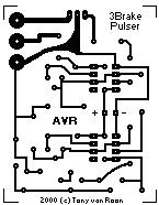
The pcb measures 2 x 2.5 inch (5 x 6.4cm or 170 x 200 pixels)
at 2 colors and is shown smaller when you print these pages.
If you need a direct, full size copy of the pcb I suggest to load the gif file into a program like Paint Shop Pro or one of the many gif viewers available.
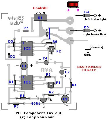
The layout is enlarged a bit for a better component view. Note that Q1 is drawn soldered on the pcb but if you have a metal case you can put it anywhere on the metal case (as a coolrib) and use havy duty wiring between Q1 and the PCB.
I tested different semiconductors like the 1N5401/1N5404, NTE153, and 4A type powerdiodes for D4/D5. All worked very well. As expected, Q1 is getting very hot. Current draw was measured between 680 - 735mA with a regular automotive 'headlight' bulb, extra heavy duty to make sure the circuit was safe. I tested several other power transistors including some darlingtons like the TIP125 and the TIP147. I eventually settled for the TIP125 myself because I had it available but any thing with 5A or more will do fine.
The actual third brake bulb is a lot smaller. Adjusting the trimpots (P1/P2) may take a bit of patience but really fine-tunes the circuit well. The only drawback of this circuit is the discharge lag coming from the electrolytic capacitor C2 and the R4 resistor. Especially if the brakes are used often or at short intervals the third brake light will not flash or maybe flash once or twice. Again, this is because the R-C combo does not have enough time to discharge in between braking. It takes about 12 seconds to discharge C2.
The pcb measures 2 x 2.5 inch (5 x 6.4cm or 170 x 200 pixels)
at 2 colors and is shown smaller when you print these pages.
If you need a direct, full size copy of the pcb I suggest to load the gif file into a program like Paint Shop Pro or one of the many gif viewers available.
The layout is enlarged a bit for a better component view. Note that Q1 is drawn soldered on the pcb but if you have a metal case you can put it anywhere on the metal case (as a coolrib) and use havy duty wiring between Q1 and the PCB.
CORRECTION: SCR1's anode/kathode
were shown reversed (fixed: 2-26-2000).
were shown reversed (fixed: 2-26-2000).
Author: Tony van Roon
声明:本文内容及配图由入驻作者撰写或者入驻合作网站授权转载。文章观点仅代表作者本人,不代表电子发烧友网立场。文章及其配图仅供工程师学习之用,如有内容侵权或者其他违规问题,请联系本站处理。
举报投诉
发布评论请先 登录
相关推荐
热点推荐
SiLM42281CN-AQ 三通道150mA线性LED驱动,独立PWM调光,RUN总线级联代替E522.81
上报?SiLM42281CN-AQ三通道线性LED驱动器,正是为汽车级高可靠性LED照明而设计。
在汽车尾灯、转向灯、刹车灯及内部照明中,常需多路恒流LED驱动,并需满足诊断、调光和热管理要求
发表于 05-20 08:13
惠海大功率LED降压恒流驱动IC H5628K 支持100V80V60V48V36V24V降压12V9V2.5A大电流
:
· MODE 悬空:高亮模式,适配远光灯、刹车灯等全亮度场景;
· MODE 接高电平:自动切换为 50% 负载电流的低亮模式,适配日行灯、示宽灯等低亮度场景。无需额外增加复杂控制电路,即可实现亮度分级
发表于 05-13 09:36
H7604A 2.5-40V 线性恒流芯片 PWM和模拟调光 低压差恒流 过温降电流
设计的核心课题。
下面我们以尾灯模块(位置灯与刹车灯复用)为例,结合惠海半导体 H7604A 高调光性能 LED 线性恒流驱动器,解析车载线性驱动方案如何解决这些核心问题。
一、恒流工作设定:12V
发表于 05-06 09:48
东沃电子2026 ALE车灯展圆满落幕
第二十一届汽车灯具产业发展技术论坛暨上海国际汽车灯具展览会(ALE)于2026年3月25日至27日在昆山花桥国际博览中心圆满落幕。作为全球规模最大、专业水准最高的车灯行业盛会之一,本届ALE以“光驭
光奴未来,车灯新生态——东沃诚邀您共赴2026 ALE车灯展
2026第二十一届汽车灯具产业发展技术论坛暨上海国际汽车灯具展览会(ALE)将于2026年3月25日至27日在花桥国际博览中心盛大开幕。东沃电子(DOWOSEMI)将携汽车照明系统保护应用方案精彩亮相,诚邀业界同仁莅临展位A-T305参观交流,光奴未来 定义

电机刹车时变频器过流报警原因分析
在工业自动化控制系统中,变频器驱动电机运行时,刹车过程中出现过流报警是一种常见的故障现象。这种故障不仅影响生产效率,严重时还会损坏设备。本文将深入分析电机刹车时变频器过流报警的原因,并提出相应
芯源MCU刹车功能
设置死区时间寄存器ATIM_DTR 的BKE 位域为1,使能刹车功能。
刹车信号为高电平有效,当刹车信号有效时,比较输出通道CHxy 将立即设置为程序设定的输出状态,具体输出
状态由通道控制寄存器
发表于 12-02 06:25
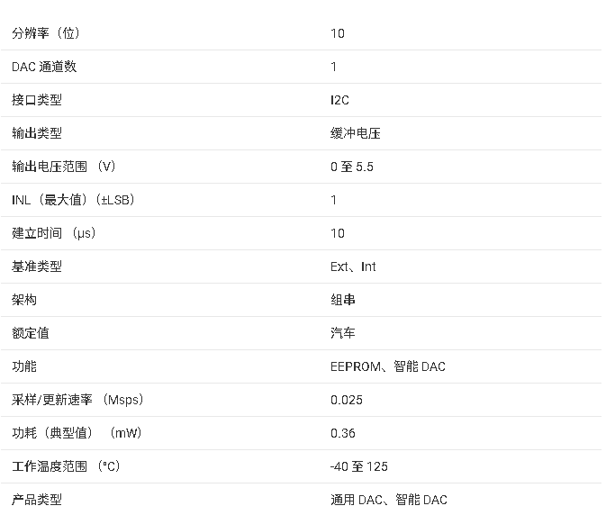
DAC53701-Q1/DAC43701-Q1 技术文档总结
引脚 WSON 封装。DACx3701-Q1 的功能集与微型封装和低功耗相结合,是汽车尾灯加刹车灯、车牌灯淡入淡出和车内灯 PWM 扩展等应用的绝佳选择。
DAC43701-Q1技术文档总结
引脚 WSON 封装。DACx3701-Q1 的功能集与微型封装和低功耗相结合,是汽车尾灯加刹车灯、车牌灯淡入淡出和车内灯 PWM 扩展等应用的绝佳选择。
热冲击试验对车灯有什么影响?
什么是热冲击试验?车辆外部照明和光信号装置的热冲击试验,是一项针对车灯环境可靠性的关键测试。它通过模拟车辆在日常使用中可能遭遇的急剧温度变化,将车灯样品交替暴露于极端高温和低温环境中,进行多次循环
安世半导体推出全新线性LED驱动器系列产品
安世半导体近期推出了12/16/24通道、每通道100mA驱动能力的线性LED驱动系列产品。该系列产品集成芯片级ASIL-B功能安全,满足车灯系统针对功能安全日渐增加的高要求,非常适用于车外照明中的转向灯、刹车灯、贯穿式尾灯,以及日间行
车灯设计:基于 LED 光源的汽车车灯设计与优化
随着科技的不断进步和社会的发展,汽车已经成为人们生活中必不可少的交通工具。而作为汽车的重要组成部分之一,车灯的设计和优化对于驾驶安全和舒适性起着至关重要的作用。近年来,基于LED光源的汽车车灯逐渐
MCU 赋能车灯多元应用:具备32位/8位不同核心的单片机解决方案
中枢组件。它不仅负责夜间与恶劣天候下的视野照明,更是车辆与外部环境实现实时互动的光学通讯接口。无论是转向意图、刹车警示,或是流光呼吸等灯光效果,车灯早已不再只是「照明」,而是嵌入智能与算法的主动式安全
发表于 08-14 18:08
LED车灯的构造与发光原理及优势
汽车灯作为夜间行车不可或缺的照明设备,随着LED技术的不断发展,越来越多的汽车制造商将LED车灯视为首选产品。LED汽车灯指的是在车辆内部和外部使用LED技术作为照明光源的灯具。外部照明设备涉及到热
80V72V60V降压12V2.5A9V1.5A DC/DC电源LED车灯恒流驱动芯片H5516L
设计,H5516L 适合以下 LED 驱动领域:
汽车照明:如汽车日行灯、转向灯、刹车灯等,可通过模式切换实现白天高亮、夜间低亮(或反之),兼顾照明与节能;
摩托车 / 电动车灯光:适配低压电源环境,外围
发表于 07-18 09:43


评论