 全志R128应用开发案例—SPI驱动ST7789V1.3寸LCD

SPI驱动ST7789V1.3寸LCD
R128 平台提供了 SPI DBI 的 SPI TFT 接口,具有如下特点:
- Supports DBI Type C 3 Line/4 Line Interface Mode
- Supports 2 Data Lane Interface Mode
- Supports data source from CPU or DMA
- Supports RGB111/444/565/666/888 video format
- Maximum resolution of RGB666 240 x 320@30Hz with single data lane
- Maximum resolution of RGB888 240 x 320@60Hz or 320 x 480@30Hz with dual data lane
- Supports tearing effect
- Supports software flexible control video frame rate
同时,提供了 SPILCD 驱动框架以供 SPI 屏幕使用。
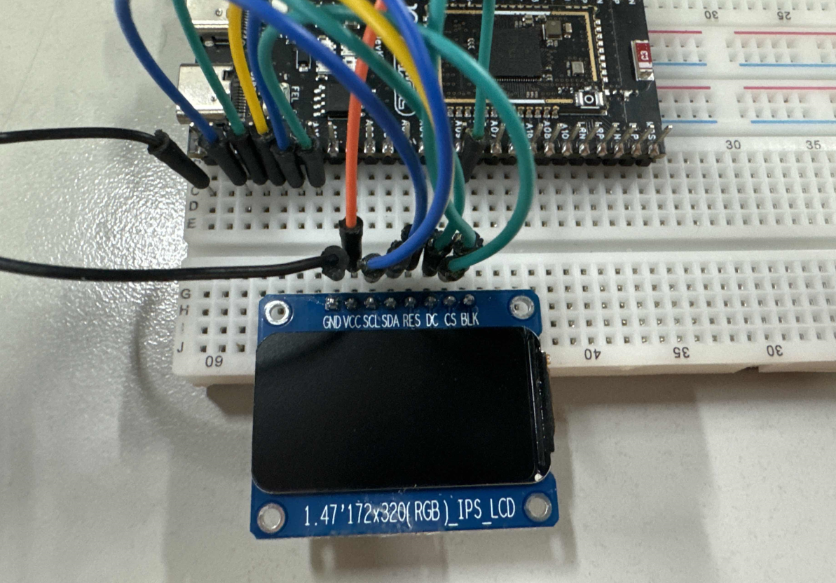
此次适配的SPI屏为 ZJY130S0800TG01,使用的是 SPI 进行驱动。
引脚配置如下:
R128 Devkit
TFT 模块
PA12
CS
PA13
SCL
PA18
SDA
PA9
BLK
PA20
RES
PA19
3V3
VCC
GND
GND
载入方案
我们使用的开发板是 R128-Devkit,需要开发 C906 核心的应用程序,所以载入方案选择 r128s2_module_c906
$ source envsetup.sh
$ lunch_rtos 1
.png")
设置 SPI 驱动
屏幕使用的是SPI驱动,所以需要勾选SPI驱动,运行 mrtos_menuconfig 进入配置页面。前往下列地址找到 SPI Devices
Drivers Options  --- >
    soc related device drivers  --- >
        SPI Devices --- >
        -*- enable spi driver
.png")
配置 SPI 引脚
打开你喜欢的编辑器,修改文件:board/r128s2/module/configs/sys_config.fex,在这里我们不需要用到 SPI HOLD与SPI WP引脚,注释掉即可。
;----------------------------------------------------------------------------------
;SPI controller configuration
;----------------------------------------------------------------------------------
;Please config spi in dts
[spi1]
spi1_used       = 1
spi1_cs_number  = 1
spi1_cs_bitmap  = 1
spi1_cs0        = port:PA12< 6 >< 0 >< 3 >< default >
spi1_sclk       = port:PA13< 6 >< 0 >< 3 >< default >
spi1_mosi       = port:PA18< 6 >< 0 >< 3 >< default >
spi1_miso       = port:PA21< 6 >< 0 >< 3 >< default >
;spi1_hold       = port:PA19< 6 >< 0 >< 2 >< default >
;spi1_wp         = port:PA20< 6 >< 0 >< 2 >< default >
.png")
设置 PWM 驱动
屏幕背光使用的是PWM驱动,所以需要勾选PWM驱动,运行 mrtos_menuconfig 进入配置页面。前往下列地址找到 PWM Devices
Drivers Options  --- >
    soc related device drivers  --- >
        PWM Devices --- >
        -*- enable pwm driver
.png")
配置 PWM 引脚
打开你喜欢的编辑器,修改文件:board/r128s2/module/configs/sys_config.fex,增加 PWM1 节点
[pwm1]
pwm_used        = 1
pwm_positive    = port:PA9< 4 >< 0 >< 3 >< default >
.png")
设置 SPI LCD 驱动
SPI LCD 由专门的驱动管理。运行 mrtos_menuconfig 进入配置页面。前往下列地址找到 SPILCD Devices ,注意同时勾选 spilcd hal APIs test 方便测试使用。
Drivers Options  --- >
    soc related device drivers  --- >
        [*] DISP Driver Support(spi_lcd)
        [*]   spilcd hal APIs test
.png")
编写 SPI LCD 显示屏驱动
获取屏幕初始化序列
首先询问屏厂提供驱动源码

找到 LCD 的初始化序列代码

找到屏幕初始化的源码

整理后的初始化代码如下:
LCD_WR_REG(0x11); // Sleep out
delay_ms(120);    // Delay 120ms
//************* Start Initial Sequence **********//
LCD_WR_REG(0x36);
LCD_WR_DATA8(0x00);

LCD_WR_REG(0x3A);
LCD_WR_DATA8(0x05);

LCD_WR_REG(0xB2);
LCD_WR_DATA8(0x1F);
LCD_WR_DATA8(0x1F);
LCD_WR_DATA8(0x00);
LCD_WR_DATA8(0x33);
LCD_WR_DATA8(0x33);

LCD_WR_REG(0xB7);
LCD_WR_DATA8(0x35);

LCD_WR_REG(0xBB);
LCD_WR_DATA8(0x20);   // 2b

LCD_WR_REG(0xC0);
LCD_WR_DATA8(0x2C);

LCD_WR_REG(0xC2);
LCD_WR_DATA8(0x01);

LCD_WR_REG(0xC3);
LCD_WR_DATA8(0x01);

LCD_WR_REG(0xC4);
LCD_WR_DATA8(0x18);   // VDV, 0x20:0v

LCD_WR_REG(0xC6);
LCD_WR_DATA8(0x13);   // 0x13:60Hz

LCD_WR_REG(0xD0);
LCD_WR_DATA8(0xA4);
LCD_WR_DATA8(0xA1);

LCD_WR_REG(0xD6);
LCD_WR_DATA8(0xA1);   // sleep in后,gate输出为GND

LCD_WR_REG(0xE0);
LCD_WR_DATA8(0xF0);
LCD_WR_DATA8(0x04);
LCD_WR_DATA8(0x07);
LCD_WR_DATA8(0x04);
LCD_WR_DATA8(0x04);
LCD_WR_DATA8(0x04);
LCD_WR_DATA8(0x25);
LCD_WR_DATA8(0x33);
LCD_WR_DATA8(0x3C);
LCD_WR_DATA8(0x36);
LCD_WR_DATA8(0x14);
LCD_WR_DATA8(0x12);
LCD_WR_DATA8(0x29);
LCD_WR_DATA8(0x30);

LCD_WR_REG(0xE1);
LCD_WR_DATA8(0xF0);
LCD_WR_DATA8(0x02);
LCD_WR_DATA8(0x04);
LCD_WR_DATA8(0x05);
LCD_WR_DATA8(0x05);
LCD_WR_DATA8(0x21);
LCD_WR_DATA8(0x25);
LCD_WR_DATA8(0x32);
LCD_WR_DATA8(0x3B);
LCD_WR_DATA8(0x38);
LCD_WR_DATA8(0x12);
LCD_WR_DATA8(0x14);
LCD_WR_DATA8(0x27);
LCD_WR_DATA8(0x31);

LCD_WR_REG(0xE4);
LCD_WR_DATA8(0x1D);   // 使用240根gate  (N+1)*8
LCD_WR_DATA8(0x00);   // 设定gate起点位置
LCD_WR_DATA8(0x00);   // 当gate没有用完时,bit4(TMG)设为0

LCD_WR_REG(0x21);

LCD_WR_REG(0x29);
用现成驱动改写 SPI LCD 驱动
选择一个现成的 SPI LCD 改写即可,这里选择 nv3029s.c 驱动来修改
.png")
复制这两个驱动,重命名为 st7789v.c
.png")
先编辑 st7789v.h 将 nv3029s 改成 st7789v
.png")
#ifndef _ST7789V_H
#define _ST7789V_H

#include "panels.h"

struct __lcd_panel st7789v_panel;

#endif /*End of file*/
编辑 st7789v.c 将 nv3029s 改成 st7789v
.png")
编写初始化序列
先删除 static void LCD_panel_init(unsigned int sel) 中的初始化函数。
.png")
然后将屏厂提供的初始化序列复制进来

然后按照 spi_lcd 框架的接口改写驱动接口,具体接口如下
屏厂函数
SPILCD框架接口
LCD_WR_REG
sunxi_lcd_cmd_write
LCD_WR_DATA8
sunxi_lcd_para_write
delay_ms
sunxi_lcd_delay_ms
可以直接进行替换
.png")
完成后如下
.png")
然后对照屏厂提供的驱动修改 address 函数
.png")
做如下修改
static void address(unsigned int sel, int x, int y, int width, int height)
{
    sunxi_lcd_cmd_write(sel, 0x2B); /* Set row address */
    sunxi_lcd_para_write(sel, (y > > 8) & 0xff);
    sunxi_lcd_para_write(sel, y & 0xff);
    sunxi_lcd_para_write(sel, (height > > 8) & 0xff);
    sunxi_lcd_para_write(sel, height & 0xff);
    sunxi_lcd_cmd_write(sel, 0x2A); /* Set coloum address */
    sunxi_lcd_para_write(sel, (x > > 8) & 0xff);
    sunxi_lcd_para_write(sel, x & 0xff);
    sunxi_lcd_para_write(sel, (width > > 8) & 0xff);
    sunxi_lcd_para_write(sel, width & 0xff);
    sunxi_lcd_cmd_write(sel, 0x2c);
}
完成驱动如下
#include "st7789v.h"

static void LCD_power_on(u32 sel);
static void LCD_power_off(u32 sel);
static void LCD_bl_open(u32 sel);
static void LCD_bl_close(u32 sel);
static void LCD_panel_init(u32 sel);
static void LCD_panel_exit(u32 sel);
#define RESET(s, v) sunxi_lcd_gpio_set_value(s, 0, v)
#define power_en(sel, val) sunxi_lcd_gpio_set_value(sel, 0, val)

static struct disp_panel_para info[LCD_FB_MAX];

static void address(unsigned int sel, int x, int y, int width, int height)
{
    sunxi_lcd_cmd_write(sel, 0x2B); /* Set row address */
    sunxi_lcd_para_write(sel, (y > > 8) & 0xff);
    sunxi_lcd_para_write(sel, y & 0xff);
    sunxi_lcd_para_write(sel, (height > > 8) & 0xff);
    sunxi_lcd_para_write(sel, height & 0xff);
    sunxi_lcd_cmd_write(sel, 0x2A); /* Set coloum address */
    sunxi_lcd_para_write(sel, (x > > 8) & 0xff);
    sunxi_lcd_para_write(sel, x & 0xff);
    sunxi_lcd_para_write(sel, (width > > 8) & 0xff);
    sunxi_lcd_para_write(sel, width & 0xff);
    sunxi_lcd_cmd_write(sel, 0x2c);
}

static void LCD_panel_init(unsigned int sel)
{
    if (bsp_disp_get_panel_info(sel, &info[sel])) {
        lcd_fb_wrn("get panel info fail!n");
        return;
    }

    sunxi_lcd_cmd_write(sel, 0x11); // Sleep out
    sunxi_lcd_delay_ms(120);    // Delay 120ms
    //************* Start Initial Sequence **********//
    sunxi_lcd_cmd_write(sel, 0x36);
    sunxi_lcd_para_write(sel, 0x00);

    sunxi_lcd_cmd_write(sel, 0x3A);
    sunxi_lcd_para_write(sel, 0x05);

    sunxi_lcd_cmd_write(sel, 0xB2);
    sunxi_lcd_para_write(sel, 0x1F);
    sunxi_lcd_para_write(sel, 0x1F);
    sunxi_lcd_para_write(sel, 0x00);
    sunxi_lcd_para_write(sel, 0x33);
    sunxi_lcd_para_write(sel, 0x33);

    sunxi_lcd_cmd_write(sel, 0xB7);
    sunxi_lcd_para_write(sel, 0x35);

    sunxi_lcd_cmd_write(sel, 0xBB);
    sunxi_lcd_para_write(sel, 0x20);   // 2b

    sunxi_lcd_cmd_write(sel, 0xC0);
    sunxi_lcd_para_write(sel, 0x2C);

    sunxi_lcd_cmd_write(sel, 0xC2);
    sunxi_lcd_para_write(sel, 0x01);

    sunxi_lcd_cmd_write(sel, 0xC3);
    sunxi_lcd_para_write(sel, 0x01);

    sunxi_lcd_cmd_write(sel, 0xC4);
    sunxi_lcd_para_write(sel, 0x18);   // VDV, 0x20:0v

    sunxi_lcd_cmd_write(sel, 0xC6);
    sunxi_lcd_para_write(sel, 0x13);   // 0x13:60Hz

    sunxi_lcd_cmd_write(sel, 0xD0);
    sunxi_lcd_para_write(sel, 0xA4);
    sunxi_lcd_para_write(sel, 0xA1);

    sunxi_lcd_cmd_write(sel, 0xD6);
    sunxi_lcd_para_write(sel, 0xA1);   // sleep in后,gate输出为GND

    sunxi_lcd_cmd_write(sel, 0xE0);
    sunxi_lcd_para_write(sel, 0xF0);
    sunxi_lcd_para_write(sel, 0x04);
    sunxi_lcd_para_write(sel, 0x07);
    sunxi_lcd_para_write(sel, 0x04);
    sunxi_lcd_para_write(sel, 0x04);
    sunxi_lcd_para_write(sel, 0x04);
    sunxi_lcd_para_write(sel, 0x25);
    sunxi_lcd_para_write(sel, 0x33);
    sunxi_lcd_para_write(sel, 0x3C);
    sunxi_lcd_para_write(sel, 0x36);
    sunxi_lcd_para_write(sel, 0x14);
    sunxi_lcd_para_write(sel, 0x12);
    sunxi_lcd_para_write(sel, 0x29);
    sunxi_lcd_para_write(sel, 0x30);

    sunxi_lcd_cmd_write(sel, 0xE1);
    sunxi_lcd_para_write(sel, 0xF0);
    sunxi_lcd_para_write(sel, 0x02);
    sunxi_lcd_para_write(sel, 0x04);
    sunxi_lcd_para_write(sel, 0x05);
    sunxi_lcd_para_write(sel, 0x05);
    sunxi_lcd_para_write(sel, 0x21);
    sunxi_lcd_para_write(sel, 0x25);
    sunxi_lcd_para_write(sel, 0x32);
    sunxi_lcd_para_write(sel, 0x3B);
    sunxi_lcd_para_write(sel, 0x38);
    sunxi_lcd_para_write(sel, 0x12);
    sunxi_lcd_para_write(sel, 0x14);
    sunxi_lcd_para_write(sel, 0x27);
    sunxi_lcd_para_write(sel, 0x31);

    sunxi_lcd_cmd_write(sel, 0xE4);
    sunxi_lcd_para_write(sel, 0x1D);   // 使用240根gate  (N+1)*8
    sunxi_lcd_para_write(sel, 0x00);   // 设定gate起点位置
    sunxi_lcd_para_write(sel, 0x00);   // 当gate没有用完时,bit4(TMG)设为0

    sunxi_lcd_cmd_write(sel, 0x21);

    sunxi_lcd_cmd_write(sel, 0x29);

    if (info[sel].lcd_x < info[sel].lcd_y)
        address(sel, 0, 0, info[sel].lcd_x - 1, info[sel].lcd_y - 1);
    else
        address(sel, 0, 0, info[sel].lcd_y - 1, info[sel].lcd_x - 1);
}

static void LCD_panel_exit(unsigned int sel)
{
    sunxi_lcd_cmd_write(sel, 0x28);
    sunxi_lcd_delay_ms(20);
    sunxi_lcd_cmd_write(sel, 0x10);
    sunxi_lcd_delay_ms(20);
    sunxi_lcd_pin_cfg(sel, 0);
}

static s32 LCD_open_flow(u32 sel)
{
    lcd_fb_here;
    /* open lcd power, and delay 50ms */
    LCD_OPEN_FUNC(sel, LCD_power_on, 50);
    /* open lcd power, than delay 200ms */
    LCD_OPEN_FUNC(sel, LCD_panel_init, 200);

    LCD_OPEN_FUNC(sel, lcd_fb_black_screen, 50);
    /* open lcd backlight, and delay 0ms */
    LCD_OPEN_FUNC(sel, LCD_bl_open, 0);

    return 0;
}

static s32 LCD_close_flow(u32 sel)
{
    lcd_fb_here;
    /* close lcd backlight, and delay 0ms */
    LCD_CLOSE_FUNC(sel, LCD_bl_close, 50);
    /* open lcd power, than delay 200ms */
    LCD_CLOSE_FUNC(sel, LCD_panel_exit, 10);
    /* close lcd power, and delay 500ms */
    LCD_CLOSE_FUNC(sel, LCD_power_off, 10);

    return 0;
}

static void LCD_power_on(u32 sel)
{
    /* config lcd_power pin to open lcd power0 */
    lcd_fb_here;
    power_en(sel, 1);

    sunxi_lcd_power_enable(sel, 0);

    sunxi_lcd_pin_cfg(sel, 1);
    RESET(sel, 1);
    sunxi_lcd_delay_ms(100);
    RESET(sel, 0);
    sunxi_lcd_delay_ms(100);
    RESET(sel, 1);
}

static void LCD_power_off(u32 sel)
{
    lcd_fb_here;
    /* config lcd_power pin to close lcd power0 */
    sunxi_lcd_power_disable(sel, 0);
    power_en(sel, 0);
}

static void LCD_bl_open(u32 sel)
{
    sunxi_lcd_pwm_enable(sel);
    /* config lcd_bl_en pin to open lcd backlight */
    sunxi_lcd_backlight_enable(sel);
    lcd_fb_here;
}

static void LCD_bl_close(u32 sel)
{
    /* config lcd_bl_en pin to close lcd backlight */
    sunxi_lcd_backlight_disable(sel);
    sunxi_lcd_pwm_disable(sel);
    lcd_fb_here;
}


/* sel: 0:lcd0; 1:lcd1 */
static s32 LCD_user_defined_func(u32 sel, u32 para1, u32 para2, u32 para3)
{
    lcd_fb_here;
    return 0;
}

static int lcd_set_var(unsigned int sel, struct fb_info *p_info)
{
    return 0;
}

static int lcd_set_addr_win(unsigned int sel, int x, int y, int width, int height)
{
    address(sel, x, y, width, height);
    return 0;
}

static int lcd_blank(unsigned int sel, unsigned int en)
{
    return 0;
}

struct __lcd_panel st7789v_panel = {
    /* panel driver name, must mach the name of lcd_drv_name in sys_config.fex
       */
    .name = "st7789v",
    .func = {
        .cfg_open_flow = LCD_open_flow,
        .cfg_close_flow = LCD_close_flow,
        .lcd_user_defined_func = LCD_user_defined_func,
        .blank = lcd_blank,
        .set_var = lcd_set_var,
        .set_addr_win = lcd_set_addr_win,
    },
};
对接驱动框架
完成了屏幕驱动的编写,接下来需要对接到 SPILCD 驱动框架。首先编辑 Kconfig
.png")
增加 st7789v 的配置
.png")
config LCD_SUPPORT_ST7789V
    bool "LCD support st7789v panel"
    default n
    ---help---
        If you want to support st7789v panel for display driver, select it.
然后编辑 panels.c 在 panel_array 里增加 st7789 驱动的引用
.png")
如下图
.png")
#ifdef CONFIG_LCD_SUPPORT_ST7789V
    &st7789v_panel,
#endif
之后编辑 panels.h 同样增加引用
.png")
如下图
.png")
#ifdef CONFIG_LCD_SUPPORT_ST7789V
extern struct __lcd_panel st7789v_panel;
#endif
最后编辑外层的 Makefile 增加编译选项
.png")
如下所示
.png")
obj-${CONFIG_LCD_SUPPORT_ST7789V} += panels/st7789v.o
选择 ST7789V 驱动
在 SPILCD 驱动选择界面可以看到 LCD_FB panels select 选择 SPI 屏幕的驱动
进入 LCD_FB panels select 选项
.png")
选择并勾选 [*] LCD support st7789v panel
.png")
配置 SPI LCD 引脚
打开你喜欢的编辑器,修改文件:board/r128s2/module/configs/sys_config.fex
[lcd_fb0]
lcd_used            = 1
lcd_model_name      = "spilcd"
lcd_driver_name     = "st7789v"
; 屏幕规格配置
lcd_x               = 240
lcd_y               = 240
lcd_width           = 32
lcd_height          = 32
; SPI 速率
lcd_data_speed      = 50
; PWM 背光配置项
lcd_pwm_used        = 1
lcd_pwm_ch          = 1
lcd_pwm_freq        = 5000
lcd_pwm_pol         = 0
lcd_backlight       = 100
; 配置 lcd_if = 1 为 SPI 模式,双缓冲
lcd_if              = 0
fb_buffer_num       = 2
; SPI 模式下以下配置无效
lcd_pixel_fmt       = 11
lcd_dbi_fmt         = 2
lcd_dbi_clk_mode    = 1
lcd_dbi_te          = 1
lcd_dbi_if          = 4
lcd_rgb_order       = 0
lcd_fps             = 60
; 使用 SPI1 作为通讯接口
lcd_spi_bus_num     = 1
lcd_frm             = 2
lcd_gamma_en        = 1

lcd_power_num       = 0
lcd_gpio_regu_num   = 0
lcd_bl_percent_num  = 0

lcd_spi_dc_pin      = port:PA19< 1 >< 0 >< 3 >< 0 >
;RESET Pin
lcd_gpio_0          = port:PA20< 1 >< 0 >< 2 >< 0 >
编译打包
运行命令 mp 编译打包,可以看到编译了 st7789v.o
.png")
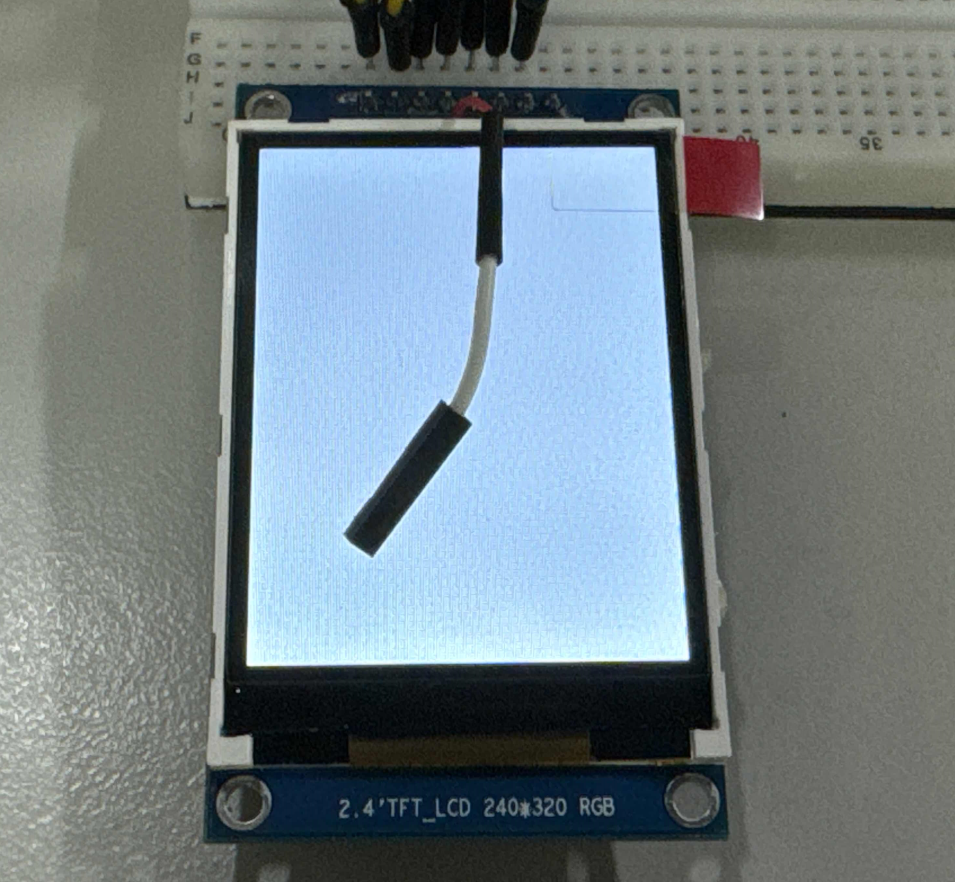
测试
烧录启动之后,屏幕背光启动,但是屏幕全黑。
.png")
输入 test_spilcd ,屏幕显示黄色。


输入 lv_examples 1 可以显示 lvgl 界面

常见问题
LVGL 出现 DMA OVER SIZE
.png")
这是由于 LVGL 配置的 LV_COLOR_DEPTH 为 32,但是 SPI 屏配置为16位。请修改 lv_conf.h
.png")
出现部分花屏
.png")
- 检查
address函数是否正确 - 检查
sys_config.fex屏幕配置分辨率是否正确
-
驱动器
+关注
关注
54文章
9116浏览量
156518 -
RGB
+关注
关注
4文章
836浏览量
62235 -
LCD屏
+关注
关注
0文章
132浏览量
16626 -
SPI接口
+关注
关注
0文章
287浏览量
36896 -
ST7789V
+关注
关注
3文章
6浏览量
7036 -
R128
+关注
关注
0文章
41浏览量
422
发布评论请先 登录


评论