 网络工程师综合实验,非常值得一做!

实验操作
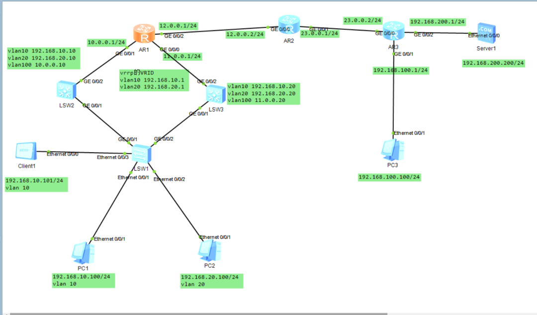
实验要求:
1、需求VRRP 正常情况下VLAN10的Master为SW1;VLAN20的Master为SW2
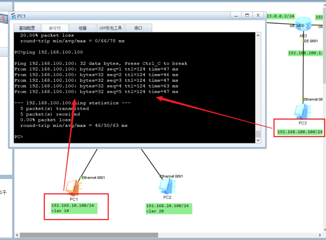
2、PC1ping通PC3
3、使用Easy Ip进行转换使得Client1能够使用R1的g0/0/2的IP访问外网
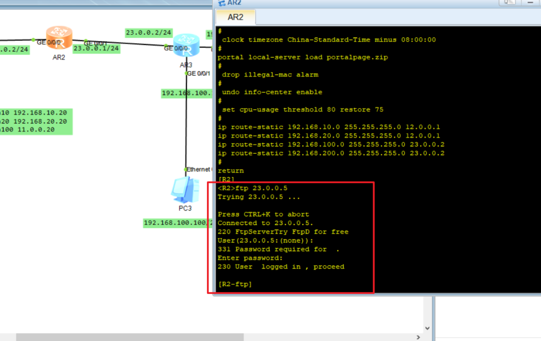
4、使用NAT-server使得Client1访问server的Web服务,并且能够使用R3的g0/0/0接口进行登陆FTP。
sw1配置(二层交换机)
配置思路:
与计算机连接的接口模式为access模式,与三层交换机相连接的为trunk,客户端和pc1都为vlan 10,pc2位vlan 20.且上行两个接口都至少需要vlan 10和vlan 20允许通过,因为三层交换机互为主备,所以两边都要可以实现通过。
sys#进入系统模式
Entersystemview,returnuserviewwithCtrl+Z.
[Huawei]sysnameSW1#修改名称
[SW1]undoinfo-centerenable#取消提示
Info:Informationcenterisdisabled.
[SW1]vlanbatch1020#创建vlan1020
Info:Thisoperationmaytakeafewseconds.Pleasewaitforamoment...done.

[SW1]inte0/0/1#进入接口e0/0/1
[SW1-Ethernet0/0/1]portlink-typeaccess#设置为access模式
[SW1-Ethernet0/0/1]portdefaultvlan10#默认vlan为10
[SW1-Ethernet0/0/1]undoshutdown#开启端口
Info:InterfaceEthernet0/0/1isnotshutdown.

[SW1-Ethernet0/0/1]inte0/0/2#进入接口e0/0/2
[SW1-Ethernet0/0/2]portlink-typeaccess#设置为access模式
[SW1-Ethernet0/0/2]portdefaultvlan20#默认vlan为20
[SW1-Ethernet0/0/2]undoshutdown#开启端口
Info:InterfaceEthernet0/0/2isnotshutdown.

[SW1-Ethernet0/0/2]inte0/0/3#进入接口e0/0/3
[SW1-Ethernet0/0/3]portlink-typeaccess#设置为access模式
[SW1-Ethernet0/0/3]portdefaultvlan10#设置默认vlan
[SW1-Ethernet0/0/3]undoshutdown#开启端口
Info:InterfaceEthernet0/0/3isnotshutdown.

[SW1-Ethernet0/0/3]intg0/0/1#进入g0/0/1接口
[SW1-GigabitEthernet0/0/1]portlink-typetrunk#设置trunk模式
[SW1-GigabitEthernet0/0/1]porttrunkallow-passvlanall#设置所有vlan允许通过
[SW1-GigabitEthernet0/0/1]undoshutdown#开启端口
Info:InterfaceGigabitEthernet0/0/1isnotshutdown.

[SW1-GigabitEthernet0/0/1]intg0/0/2#进入g0/0/2接口
[SW1-GigabitEthernet0/0/2]portlink-typetrunk#设置trunk模式
[SW1-GigabitEthernet0/0/2]porttrunkallow-passvlanall#设置所有vlan允许通过
[SW1-GigabitEthernet0/0/2]undoshutdown#开启端口
Info:InterfaceGigabitEthernet0/0/2isnotshutdown.
[SW1-GigabitEthernet0/0/2]q
SW2配置(三层交换机)
配置思路:
三层交换机具有路由器和交换的功能,但是接口无法直接设置ip,所以需要通过创建Vlan来设置虚拟ip,设置好虚拟ip之后然后再在实际接口中允许所创建的vlan通过。因为sw2是pc1的主链路,所以在设置vrrp时,需要将它的优先级设置高一点,pc2在sw2上的链路是备链路,所以优先级暂不设置,默认100。因为三层交换机与R1不在同一网段,所以需要设置默认路由可以实现与路由器AR1的通信。
sys#进入系统模式
Entersystemview,returnuserviewwithCtrl+Z.
[Huawei]sysnameSW2#修改名称
[SW2]undoinfo-centerenable#关闭提示
Info:Informationcenterisdisabled.
[SW2]vlanbatch1020100#创建vlan
Info:Thisoperationmaytakeafewseconds.Pleasewaitforamoment...done.

[SW2]intvlanif10#进入虚拟接口vlanif10
[SW2-Vlanif10]ipadd192.168.10.1024#设置接口ip
[SW2-Vlanif10]vrrpvrid1virtual-ip192.168.10.1#设置虚拟ip
[SW2-Vlanif10]vrrpvrid1priority120#设置优先级120
[SW2-Vlanif10]vrrpvrid1preempt-modetimerdelay5#设置抢占时间5s
[SW2-Vlanif10]vrrpvrid1trackintg0/0/2reduced30#监控上行接口
[SW2-Vlanif10]vrrpvrid1trackintg0/0/1reduced30#监控下行接口
[SW2-Vlanif10]dith#查看所有配置
#
interfaceVlanif10
ipaddress192.168.10.10255.255.255.0
vrrpvrid1virtual-ip192.168.10.1
vrrpvrid1priority120
vrrpvrid1preempt-modetimerdelay5
vrrpvrid1trackinterfaceGigabitEthernet0/0/2reduced30
vrrpvrid1trackinterfaceGigabitEthernet0/0/1reduced30
#
return
[SW2-Vlanif10]q#返回

[SW2]intvlanif20#进入虚拟接口vlanif20
[SW2-Vlanif20]ipadd192.168.20.2024#配置接口ip
[SW2-Vlanif20]vrrpvrid2virtual-ip192.168.20.1#配置虚拟ip
[SW2-Vlanif20]dith#查看配置
#
interfaceVlanif20
ipaddress192.168.20.20255.255.255.0
vrrpvrid2virtual-ip192.168.20.1
#
return
[SW2-Vlanif20]q#返回

[SW2]intg0/0/1#进入接口g0/0/1
[SW2-GigabitEthernet0/0/1]portlink-typetrunk#配置trunk模式
[SW2-GigabitEthernet0/0/1]porttrunkallow-passvlanall#设置所有vlan允许通过
[SW2-GigabitEthernet0/0/1]dith#查看配置
#
interfaceGigabitEthernet0/0/1
portlink-typetrunk
porttrunkallow-passvlan2to4094
#
return
[SW2-GigabitEthernet0/0/1]undoshutdown#启动接口
Info:InterfaceGigabitEthernet0/0/1isnotshutdown.
[SW2-GigabitEthernet0/0/1]q#返回

[SW2]intvlanif100#进入虚拟接口vlanif100
[SW2-Vlanif100]ipadd10.0.0.1024#设置接口ip
[SW2-Vlanif100]q#返回

[SW2]intg0/0/2#进入g0/0/2接口
[SW2-GigabitEthernet0/0/2]portlink-typeaccess#设置access模式
[SW2-GigabitEthernet0/0/2]portdefaultvlan100#设置默认vlan100
[SW2-GigabitEthernet0/0/2]undoshutdown#开启接口
Info:InterfaceGigabitEthernet0/0/2isnotshutdown.
[SW2-GigabitEthernet0/0/2]dith#查看配置
#
interfaceGigabitEthernet0/0/2
portlink-typeaccess
portdefaultvlan100
#
return
[SW2-GigabitEthernet0/0/2]q#返回

[SW2]iproute-static0.0.0.00.0.0.010.0.0.1#配置默认路由
SW3配置(三层交换机)
三层交换机具有路由器和交换的功能,但是接口无法直接设置ip,所以需要通过创建Vlan来设置虚拟ip,设置好虚拟ip之后然后再在实际接口中允许所创建的vlan通过。因为sw3是pc2的主链路,所以在设置vrrp时,需要将它的优先级设置高一点,同理,pc1在sw3上的链路是备链路,所有优先级暂不设置,默认100。最后设置一个默认路由器,因为三层交换机与R1不在同一网段,所以设置默认路由可以实现与路由器AR1的通信。
sys#进入系统模式
Entersystemview,returnuserviewwithCtrl+Z.
[Huawei]sysnameSW3#修改名称
[SW3]undoinfo-centerenable#关闭提示
Info:Informationcenterisdisabled.
[SW3]vlanbatch1020100#创建vlan1020100
Info:Thisoperationmaytakeafewseconds.Pleasewaitforamoment...done.

[SW3]intvlanif10#进入虚拟接口vlanif10
[SW3-Vlanif10]ipadd192.168.10.2024#设置接口ip
[SW3-Vlanif10]vrrpvrid1virtual-ip192.168.10.1#设置虚拟ip
[SW3-Vlanif10]dith#查看接口
#
interfaceVlanif10
ipaddress192.168.10.20255.255.255.0
vrrpvrid1virtual-ip192.168.10.1
#
return
[SW3-Vlanif10]q#返回

[SW3]intvlanif20#进入虚拟接口vlanif20
[SW3-Vlanif20]ipadd192.168.20.1024#设置接口ip
[SW3-Vlanif20]vrrpvrid2virtual-ip192.168.20.1#设置虚拟ip
[SW3-Vlanif20]vrrpvrid2priority120#设置优先级120
[SW3-Vlanif20]vrrpvrid2preempt-modetimerdelay5#设置抢占时间5s
[SW3-Vlanif20]vrrpvrid2trackintg0/0/2reduced30#监控上行接口
[SW3-Vlanif20]vrrpvrid2trackintg0/0/1reduced30#监控下行接口
[SW3-Vlanif20]dith#查看命令
#
interfaceVlanif20
ipaddress192.168.20.20255.255.255.0
vrrpvrid2virtual-ip192.168.20.1
vrrpvrid2priority120
vrrpvrid2preempt-modetimerdelay5
vrrpvrid2trackinterfaceGigabitEthernet0/0/2reduced30
vrrpvrid2trackinterfaceGigabitEthernet0/0/1reduced30
#
return
[SW3-Vlanif20]q#返回

[SW3]intvlanif100#进入虚拟接口vlanif100
[SW3-Vlanif100]ipadd11.0.0.2024#设置接口ip

[SW3]intg0/0/2#进入接口g0/0/2
[SW3-GigabitEthernet0/0/2]portlink-typeaccess#设置access模式
[SW3-GigabitEthernet0/0/2]portdefaultvlan100#默认vlan100
[SW3-GigabitEthernet0/0/2]undoshutdown#开启接口
Info:InterfaceGigabitEthernet0/0/2isnotshutdown.
[SW3-GigabitEthernet0/0/2]dith#查看配置
#
interfaceGigabitEthernet0/0/2
portlink-typeaccess
portdefaultvlan100
#
return

[SW3-GigabitEthernet0/0/2]intg0/0/1进入g0/0/1接口
[SW3-GigabitEthernet0/0/1]portlink-typetrunk#设置trunk模式
[SW3-GigabitEthernet0/0/1]porttrunkallow-passvlanall#设置允许所有vlan通过
[SW3-GigabitEthernet0/0/1]undoshutdown#开启端口
Info:InterfaceGigabitEthernet0/0/1isnotshutdown.
[SW3-GigabitEthernet0/0/1]dith#查看端口
#
interfaceGigabitEthernet0/0/1
portlink-typetrunk
porttrunkallow-passvlan2to4094
#
return
[SW3-GigabitEthernet0/0/1]q#返回

[SW3]iproute-static0.0.0.00.0.0.011.0.0.1#设置默认路由
AR1设置(路由器)
配置思路:
根据接口ip设置好各个的接口ip地址,然后启动,就开始配置静态路由,首先先配置往下的静态路由,因为根三层交换机不在同一网段,先配置往PC1的主线路sw2的静态路由,在配置往PC2的备线路sw3的浮动路由,然后先配置往PC2的主线路SW2的静态路由器,再配置往PC2备线路SW1的浮动路由,以上配置好后,再配置往右侧的静态路由,一个指向pc3,一个指向server1。然后配置结束。
sys#进入系统模式
Entersystemview,returnuserviewwithCtrl+Z.
[Huawei]sysnameR1#修改名称R1
[R1]undoinfo-centerenable#关闭提示
Info:Informationcenterisdisabled.
[R1]intg0/0/0#进入接口g0/0/0
[R1-GigabitEthernet0/0/0]ipadd11.0.0.124#设置接口ip
[R1-GigabitEthernet0/0/0]undoshutdown#开启接口
Info:InterfaceGigabitEthernet0/0/0isnotshutdown.

[R1-GigabitEthernet0/0/0]intg0/0/1#进入接口g0/0/1
[R1-GigabitEthernet0/0/1]ipadd10.0.0.124#设置接口ip
[R1-GigabitEthernet0/0/1]undoshutdown#开启端口
Info:InterfaceGigabitEthernet0/0/1isnotshutdown.

[R1-GigabitEthernet0/0/1]intg0/0/2#进入接口g0/0/2
[R1-GigabitEthernet0/0/2]ipadd12.0.0.124#设置接口ip
[R1-GigabitEthernet0/0/2]undoshutdown#开启端口
Info:InterfaceGigabitEthernet0/0/2isnotshutdown.

#设置静态路由
[R1]iproute-static192.168.10.0255.255.255.010.0.0.10
#目标网段:192.168.10.0下一跳地址:10.0.0.10
[R1]iproute-static192.168.10.0255.255.255.011.0.0.20preference70
#目标网段:192.168.10.0下一跳地址:11.0.0.20(浮动路由器,当PC1主线路端开后启用)
[R1]iproute-static192.168.20.0255.255.255.011.0.0.20
#目标网段:192.168.20.0下一跳地址:11.0.0.20
[R1]iproute-static192.168.20.0255.255.255.010.0.0.10preference70
#目标网段:192.168.20.0下一跳地址:10.0.0.10(浮动路由器,当PC2主线路端开后启用)
[R1]iproute-static192.168.100.0255.255.255.012.0.0.2
#目标网段:192.168.100.0下一跳地址:12.0.0.2
[R1]iproute-static192.168.200.0255.255.255.012.0.0.2
#目标网段:192.168.200.0下一跳地址:12.0.0.2
AR2配置(路由器)
配置思路:
首先进入接口配合ip地址,启动接口,然后配置静态路由,首先配置往左侧的两台静态路由,再配置往右侧的两条静态路由。
sys#进入系统模式
Entersystemview,returnuserviewwithCtrl+Z.
[Huawei]sysnameR2#修改名称
[R2]undoinfo-centerenable#关闭提示
Info:Informationcenterisdisabled.

[R2]intg0/0/0#进入接口g0/0/0
[R2-GigabitEthernet0/0/0]ipadd12.0.0.224#配置ip地址
[R2-GigabitEthernet0/0/0]undoshutdown#开启接口
Info:InterfaceGigabitEthernet0/0/0isnotshutdown.

[R2-GigabitEthernet0/0/0]intg0/0/1#进入接口g0/0/1
[R2-GigabitEthernet0/0/1]ipadd23.0.0.124#配置ip地址
[R2-GigabitEthernet0/0/1]undoshutdown#开启接口
Info:InterfaceGigabitEthernet0/0/1isnotshutdown.


#配置静态路由
[R2]iproute-static192.168.10.0255.255.255.012.0.0.1
#目的地址192.168.10.0下一跳地址:12.0.0.1
[R2]iproute-static192.168.20.0255.255.255.012.0.0.1
#目的地址192.168.20.0下一跳地址:12.0.0.1
[R2]iproute-static192.168.100.0255.255.255.023.0.0.2
#目的地址192.168.100.0下一跳地址:23.0.0.2
[R2]iproute-static192.168.200.0255.255.255.023.0.0.2
#目的地址192.168.200.0下一跳地址:23.0.0.2
AR3配置(路由器)
配置思路:
进入各个接口将接口ip配置然后启动,配置静态路由只需要配置默认路由就行,因为它现在处于末梢网络,只有一个出口,所以完全可以配置默认路由器。
sys#进入系统模式
Entersystemview,returnuserviewwithCtrl+Z.
[Huawei]sysnameR3#修改名称
[R3]undoinfo-centerenable#关闭提示
Info:Informationcenterisdisabled.
[R3]intg0/0/0#进入接口g0/0/0
[R3-GigabitEthernet0/0/0]ipadd23.0.0.224#配置接口ip
[R3-GigabitEthernet0/0/0]undoshutdown#启动接口
Info:InterfaceGigabitEthernet0/0/0isnotshutdown.
[R3-GigabitEthernet0/0/0]q#返回

[R3]intg0/0/1#进入接口g0/0/1
[R3-GigabitEthernet0/0/1]ipadd192.168.100.124#配置接口ip
[R3-GigabitEthernet0/0/1]undoshutdown#开启接口
Info:InterfaceGigabitEthernet0/0/1isnotshutdown.

[R3-GigabitEthernet0/0/1]intg0/0/2#进入接口g0/0/2
[R3-GigabitEthernet0/0/2]ipadd192.168.200.124#配置接口ip
[R3-GigabitEthernet0/0/2]undoshutdown#开启接口

配置静态路由
[R3]iproute-static0.0.0.00.0.0.023.0.0.1
#配置一条默认路由下一跳23.0.0.1
至目前为止,第一和第二个需求已完成,下面进行验证
第一个需求:
正常情况下线路这样走:
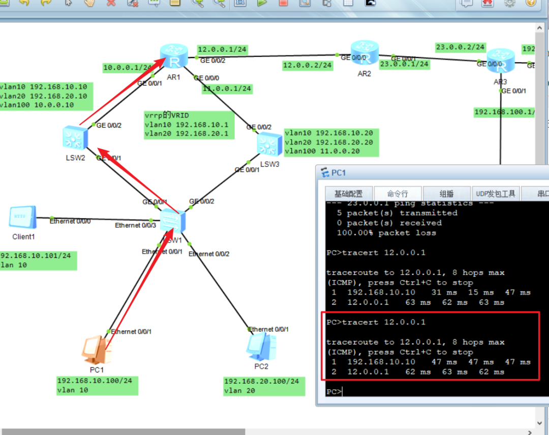
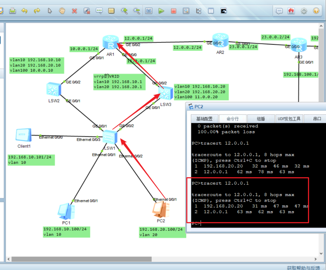
现将SW2线路断开,SW3抢占成功
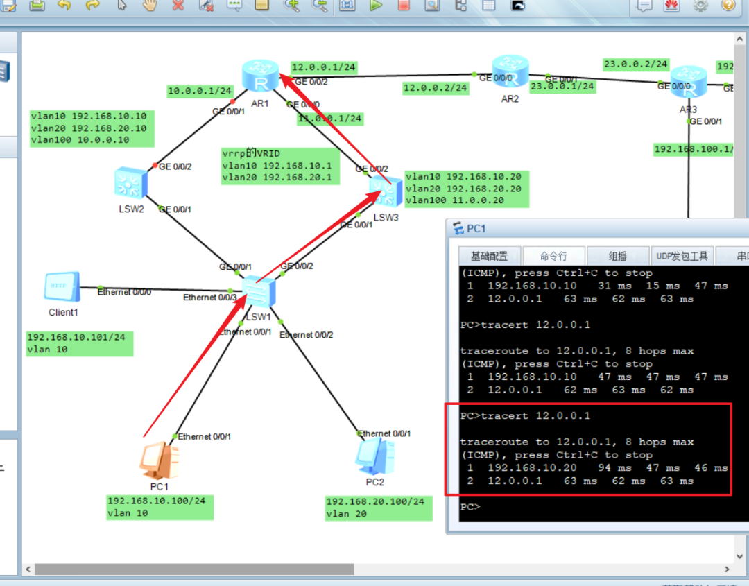
现将SW3线路切断,SW2抢占成功
第二需求:PC1 ping通 PC3
第三个和第四个还需要配置。
第三个配置:
R1配置
配置思路:Easyip配置为 将多个内网转换为一个接口外网地址,首先创建acl来进行设置哪个能否通过,然后再进入接口中映射。
sys#进入系统
Entersystemview,returnuserviewwithCtrl+Z.
[R1]acl2000#创建acl2000
[R1-acl-basic-2000]rulepermitsource192.168.10.00.0.0.255#允许192.168.10.0网段ip地址通过
[R1-acl-basic-2000]intg0/0/2#进入g0/0/2接口
[R1-GigabitEthernet0/0/2]natoutbound2000#将acl配置映射在这个接口上
[R1-GigabitEthernet0/0/2]q#返回
[R1]disnatoutbound#查看nat映射表

NATOutboundInformation:
--------------------------------------------------------------------------

InterfaceAclAddress-group/IP/InterfaceType
--------------------------------------------------------------------------

GigabitEthernet0/0/2200012.0.0.1easyip
--------------------------------------------------------------------------

Total:1
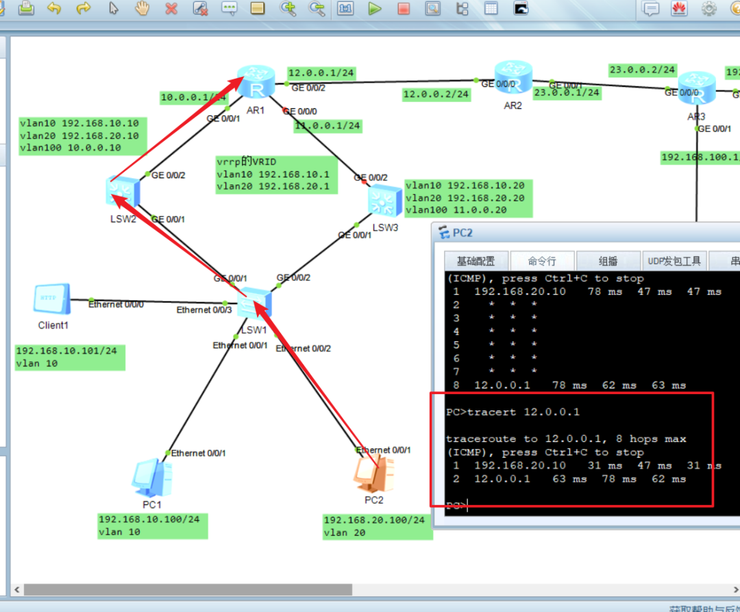
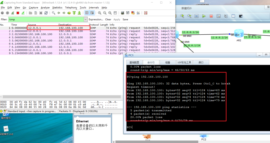
第三个需求验证:
由图可以看出,源ip地址已转换为接口ip地址。实现了转换。
第四个配置:
R3配置
配置思路:
静态PAT不需要使用ACL,直接在接口上配置私网转公网的地址,且公网地址不要与其它公网地址冲突,自定义。
sys#进入系统模式
Entersystemview,returnuserviewwithCtrl+Z.
[R3]intg0/0/0#进入接口g0/0/2
[R3-GigabitEthernet0/0/0]natserverprotocoltcpglobal23.0.0.521inside192.1
68.200.200#在接口上配置私网转公网的ip地址
[R3-GigabitEthernet0/0/0]disnatserver#查看natserver

NatServerInformation:
Interface:GigabitEthernet0/0/0
GlobalIP/Port:23.0.0.5/21(ftp)
InsideIP/Port:192.168.200.200/21(ftp)
Protocol:6(tcp)
VPNinstance-name:----
Aclnumber:----
Description:----

Total:1
[R3-GigabitEthernet0/0/0]q#返回
配置服务器server1
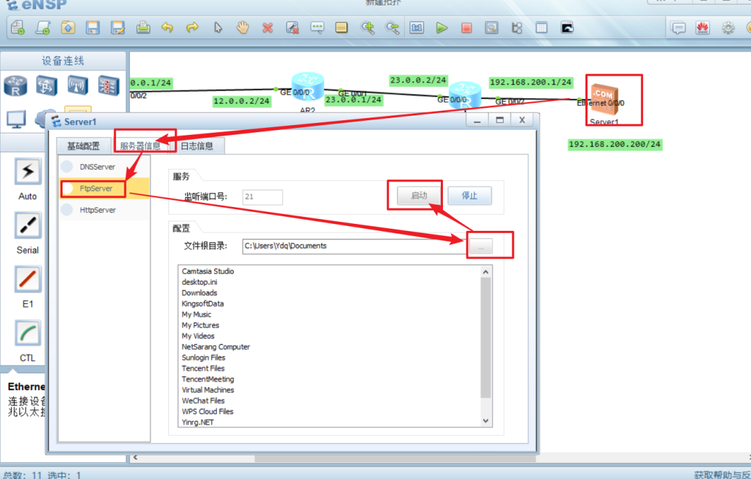
第四个需求验证:
在AR2上使用server1的公网地址,可以完成登录
在clent1上可以远程登录FTPserver1的目录。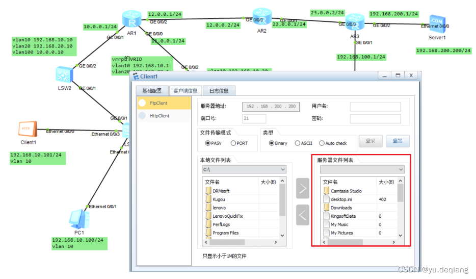
-
计算机
+关注
关注
19文章
7763浏览量
92666 -
路由器
+关注
关注
22文章
3890浏览量
118849 -
VLAN
+关注
关注
1文章
288浏览量
37511
原文标题:网络工程师综合实验,非常值得一做!
文章出处:【微信号:网络技术干货圈,微信公众号:网络技术干货圈】欢迎添加关注!文章转载请注明出处。
发布评论请先 登录


 工商网监
工商网监
评论