 基于Arduino构建一个学校自动铃声控制系统

在这篇文章中,我们将使用 Arduino、16 x 2显示器和实时时钟模块构建一个自动校铃/大学铃声系统。您可以对此项目进行编程,使其每天在您喜欢的时间和分钟敲钟多达 16次。铃声的长度可以在几秒钟内编程。
概述
当学校的牡丹敲响“锡锡丁”的铃声时,学生们飞快地跑出学校门口的日子已经一去不复返了。当牡丹在几分钟前敲响最后一声钟声时,有些人可能会更高兴。
这是15到20年前的情况,但现在所有的学校和学院都严格限制时间,钟声是自动化的。
作者的快速童年/青少年时期记得:
在我上小学和中学时,我佩戴的数字手表与学校的铃铛系统同步,精度为1秒。
上课铃响起后,我会大喊“下课铃要响5秒了”,所有学生都惊讶地盯着我,这种情况几乎每天都在发生。有一天,我和我的好朋友开始倒数10,9,8,7...在最后的钟声之前。
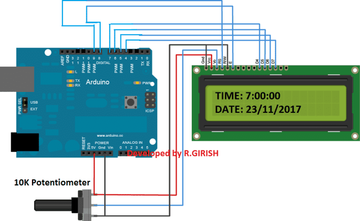
显示到 Arduino 连接
显示到 Arduino 连接与我们通常接线的略有不同,此处使用的引脚 9、8、7、6、5 和 4。引脚 2 和 3 通过按钮用作硬件中断。
使用 10K 电位计调整显示器的对比度。
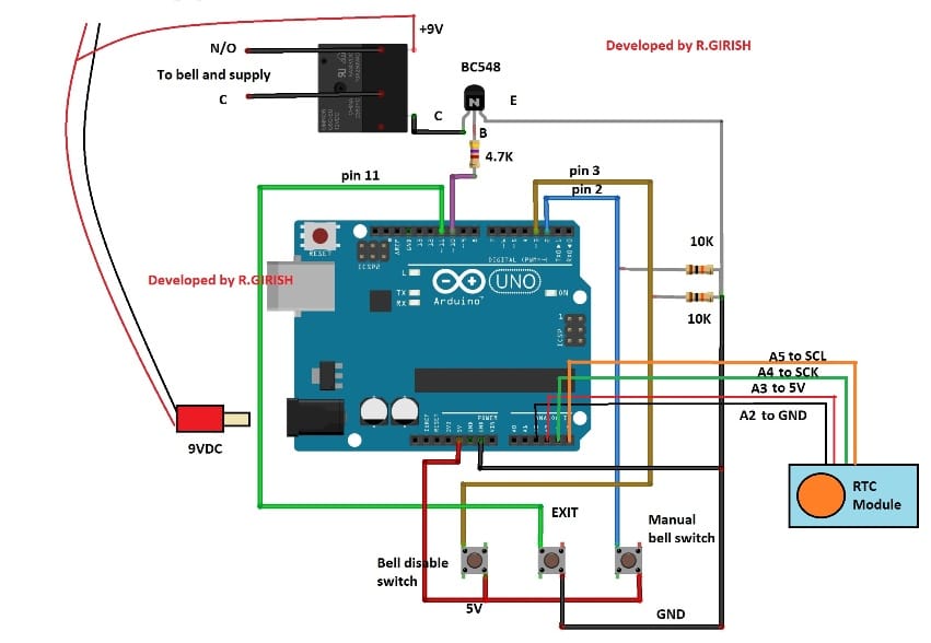
有关钟形和继电器连接的详细信息:
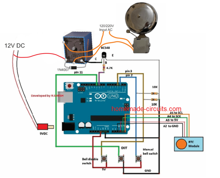
更新:A5 到 SCL 和 A4 到 SDA(不是 A4 到 SCK)
实时时钟模块
实时时钟模块即使在长时间断电后也能跟踪时间。提供 9V 继电器,用于打开和关闭铃铛。
请在继电器上连接一个反向偏置的 1N4007 二极管(原理图中未显示),这将吸收继电器有害的高压反电动势。
使用9V / 500mA墙上适配器为电路供电。
提供了三个按钮,一个用于在某些情况下手动操作铃铛。按下“退出”按钮将在手动按铃后停止铃铛。
“铃铛禁用按钮”将永远禁用铃铛。要重新启用铃铛,请按“退出”按钮。
上传下面的程序,它将时间设置为 RTC
//----------------------------------------------------//
#include 《Wire.h》
#include 《TimeLib.h》
#include 《DS1307RTC.h》
int P=A3; //Assign power pins for RTC
int N=A2;
const char *monthName[12] = {
“Jan”, “Feb”, “Mar”, “Apr”, “May”, “Jun”,
“Jul”, “Aug”, “Sep”, “Oct”, “Nov”, “Dec”
};
tmElements_t tm;
void setup() {
pinMode(P,OUTPUT);
pinMode(N,OUTPUT);
digitalWrite(P,HIGH);
digitalWrite(N,LOW);
bool parse=false;
bool config=false;
// get the date and time the compiler was run
if (getDate( DATE ) && getTime( TIME )) {
parse = true;
// and configure the RTC with this info
if (RTC.write(tm)) {
config = true;
}
}
Serial.begin(9600);
while (!Serial) ; // wait for Arduino Serial Monitor
delay(200);
if (parse && config) {
Serial.print(“DS1307 configured Time=”);
Serial.print( TIME );
Serial.print(“, Date=”);
Serial.println( DATE );
} else if (parse) {
Serial.println(“DS1307 Communication Error :-{”);
Serial.println(“Please check your circuitry”);
} else {
Serial.print(“Could not parse info from the compiler, Time=”“);
Serial.print( TIME );
Serial.print(”“, Date=”“);
Serial.print( DATE );
Serial.println(”“”);
}
}
void loop() {
}
bool getTime(const char *str)
{
int Hour, Min, Sec;
if (sscanf(str, “%d:%d:%d”, &Hour, &Min, &Sec) != 3) return
false;
tm.Hour = Hour;
tm.Minute = Min;
tm.Second = Sec;
return true;
}
bool getDate(const char *str)
{
char Month[12];
int Day, Year;
uint8_t monthIndex;
if (sscanf(str, “%s %d %d”, Month, &Day, &Year) != 3) return
false;
for (monthIndex = 0; monthIndex 《 12; monthIndex++) {
if (strcmp(Month, monthName[monthIndex]) == 0) break;
}
if (monthIndex 》= 12) return false;
tm.Day = Day;
tm.Month = monthIndex + 1;
tm.Year = CalendarYrToTm(Year);
return true;
}
//----------------------------------------------------//
After uploading the code, open the serial monitor, it will say that the
time is set.
Once the above step is accomplished successfully move on to next.
Now upload the below code to Arduino.
Main program Code:
//------------Program developed by R.GIRISH------------//
#include《EEPROM.h》
#include 《Wire.h》
#include 《TimeLib.h》
#include 《DS1307RTC.h》
#include 《LiquidCrystal.h》
LiquidCrystal lcd(9, 8, 7, 6, 5, 4);
int i = 0;
int H = 0;
int M = 0;
int S = 0;
int setting_value;
const int bell = 10;
const int P = A3;
const int N = A2;
const int setting_address = 0;
const int over_ride_off = 11;
boolean bell_status = true;
boolean Over_ride = true;
//------------------- Set Bell Timings from hours 1 to 23 hrs
-------------------//
//---- 1st bell ------//
const int h1 = 0; //hours
const int m1 = 0; //Minutes
//---- 2nd bell ------//
const int h2 = 0;
const int m2 = 0;
//---- 3rd bell ------//
const int h3 = 0;
const int m3 = 0;
//---- 4th bell ------//
const int h4 = 0;
const int m4 = 0;
//---- 5th bell ------//
const int h5 = 0;
const int m5 = 0;
//---- 6th bell ------//
const int h6 = 0;
const int m6 = 0;
//---- 7th bell ------//
const int h7 = 0;
const int m7 = 0;
//---- 8th bell ------//
const int h8 = 0;
const int m8 = 0;
//---- 9th bell ------//
const int h9 = 0;
const int m9 = 0;
//---- 10th bell ------//
const int h10 = 0;
const int m10 = 0;
//---- 11th bell ------//
const int h11 = 0;
const int m11 = 0;
//---- 12th bell ------//
const int h12 = 0;
const int m12 = 0;
//---- 13th bell ------//
const int h13 = 0;
const int m13 = 0;
//---- 14th bell ------//
const int h14 = 0;
const int m14 = 0;
//---- 15th bell ------//
const int h15 = 0;
const int m15 = 0;
//---- 16th bell ------//
const int h16 = 0;
const int m16 = 0;
//--------------- bell ring lenght in seconds -------//
const int Lenght = 3; //in seconds
//-------------------------- -------------------------//
void setup()
{
lcd.begin(16, 2);
pinMode(P, OUTPUT);
pinMode(N, OUTPUT);
pinMode(bell, OUTPUT);
pinMode(over_ride_off, INPUT);
digitalWrite(P, HIGH);
digitalWrite(N, LOW);
digitalWrite(over_ride_off, HIGH);
attachInterrupt(0, over_ride, RISING);
attachInterrupt(1, bell_setting, RISING);
if (EEPROM.read(setting_address) != 1)
{
bell_setting();
}
}
void loop()
{
tmElements_t tm;
lcd.clear();
if (RTC.read(tm))
{
H = tm.Hour;
M = tm.Minute;
S = tm.Second;
lcd.setCursor(0, 0);
lcd.print(“TIME:”);
lcd.print(tm.Hour);
lcd.print(“:”);
lcd.print(tm.Minute);
lcd.print(“:”);
lcd.print(tm.Second);
lcd.setCursor(0, 1);
lcd.print(“DATE:”);
lcd.print(tm.Day);
lcd.print(“/”);
lcd.print(tm.Month);
lcd.print(“/”);
lcd.print(tmYearToCalendar(tm.Year));
} else {
if (RTC.chipPresent())
{
lcd.setCursor(0, 0);
lcd.print(“RTC stopped!!!”);
lcd.setCursor(0, 1);
lcd.print(“Run SetTime code”);
} else {
lcd.clear();
lcd.setCursor(0, 0);
lcd.print(“Read error!”);
lcd.setCursor(0, 1);
lcd.print(“Check circuitry!”);
}
}
if (EEPROM.read(setting_address) == 1)
{
if (H == 0 && M == 0 && S == 0)
{
digitalWrite(bell, LOW);
}
if (H == h1 && M == m1 && S == 0)
{
for (i = 0; i 《 Lenght; i++)
{
digitalWrite(bell, HIGH);
delay(1000);
}
digitalWrite(bell, LOW);
i = 0;
}
if (H == h2 && M == m2 && S == 0)
{
for (i = 0; i 《 Lenght; i++)
{
digitalWrite(bell, HIGH);
delay(1000);
}
digitalWrite(bell, LOW);
i = 0;
}
if (H == h3 && M == m3 && S == 0)
{
for (i = 0; i 《 Lenght; i++)
{
digitalWrite(bell, HIGH);
delay(1000);
}
digitalWrite(bell, LOW);
i = 0;
}
if (H == h4 && M == m4 && S == 0)
{
for (i = 0; i 《 Lenght; i++)
{
digitalWrite(bell, HIGH);
delay(1000);
}
digitalWrite(bell, LOW);
i = 0;
}
if (H == h5 && M == m5 && S == 0)
{
for (i = 0; i 《 Lenght; i++)
{
digitalWrite(bell, HIGH);
delay(1000);
}
digitalWrite(bell, LOW);
i = 0;
}
if (H == h6 && M == m6 && S == 0)
{
for (i = 0; i 《 Lenght; i++)
{
digitalWrite(bell, HIGH);
delay(1000);
}
digitalWrite(bell, LOW);
i = 0;
}
if (H == h7 && M == m7 && S == 0)
{
for (i = 0; i 《 Lenght; i++)
{
digitalWrite(bell, HIGH);
delay(1000);
}
digitalWrite(bell, LOW);
i = 0;
}
if (H == h8 && M == m8 && S == 0)
{
for (i = 0; i 《 Lenght; i++)
{
digitalWrite(bell, HIGH);
delay(1000);
}
digitalWrite(bell, LOW);
i = 0;
}
if (H == h9 && M == m9 && S == 0)
{
for (i = 0; i 《 Lenght; i++)
{
digitalWrite(bell, HIGH);
delay(1000);
}
digitalWrite(bell, LOW);
i = 0;
}
if (H == h10 && M == m10 && S == 0)
{
for (i = 0; i 《 Lenght; i++)
{
digitalWrite(bell, HIGH);
delay(1000);
}
digitalWrite(bell, LOW);
i = 0;
}
if (H == h11 && M == m11 && S == 0)
{
for (i = 0; i 《 Lenght; i++)
{
digitalWrite(bell, HIGH);
delay(1000);
}
digitalWrite(bell, LOW);
i = 0;
}
if (H == h12 && M == m12 && S == 0)
{
for (i = 0; i 《 Lenght; i++)
{
digitalWrite(bell, HIGH);
delay(1000);
}
digitalWrite(bell, LOW);
i = 0;
}
if (H == h13 && M == m13 && S == 0)
{
for (i = 0; i 《 Lenght; i++)
{
digitalWrite(bell, HIGH);
delay(1000);
}
digitalWrite(bell, LOW);
i = 0;
}
if (H == h14 && M == m14 && S == 0)
{
for (i = 0; i 《 Lenght; i++)
{
digitalWrite(bell, HIGH);
delay(1000);
}
digitalWrite(bell, LOW);
i = 0;
}
if (H == h15 && M == m15 && S == 0)
{
for (i = 0; i 《 Lenght; i++)
{
digitalWrite(bell, HIGH);
delay(1000);
}
digitalWrite(bell, LOW);
i = 0;
}
if (H == h16 && M == m16 && S == 0)
{
for (i = 0; i 《 Lenght; i++)
{
digitalWrite(bell, HIGH);
delay(1000);
}
digitalWrite(bell, LOW);
i = 0;
}
}
delay(1000);
}
void over_ride()
{
lcd.clear();
while (Over_ride)
{
digitalWrite(bell, HIGH);
lcd.setCursor(0, 0);
lcd.print(“Press Exit to”);
lcd.setCursor(0, 1);
lcd.print(“Stop the bell!!!”);
if (digitalRead(over_ride_off) == LOW)
{
Over_ride = false;
digitalWrite(bell, LOW);
}
}
Over_ride = true;
}
void bell_setting()
{
setting_value = 0;
EEPROM.write(setting_address, setting_value);
lcd.clear();
while (bell_status)
{
lcd.setCursor(0, 0);
lcd.print(“Bell is Disabled”);
lcd.setCursor(0, 1);
lcd.print(“Press Exit.”);
if (digitalRead(over_ride_off) == LOW)
{
bell_status = false;
}
}
bell_status = true;
setting_value = 1;
EEPROM.write(setting_address, setting_value);
}
//------------Program developed by R.GIRISH------------//
上传上述代码后,您应该在显示屏上看到以小时为单位的时间。
如何使用这个自动铃铛系统:
在完成硬件设置后执行此操作。
1.先上传“时间设置”代码,然后打开串行监视器。
2.在主程序中设置需要触发继电器的时间 这里。
//---- 1st bell ------//
const int h1 = 0; //hours
const int m1 = 0; //Minutes
//---- 2nd bell ------//
const int h2 = 0;
const int m2 = 0;
//---- 3rd bell ------//
const int h3 = 0;
const int m3 = 0;
//---- 4th bell ------//
const int h4 = 0;
const int m4 = 0;
• 从 1 到 1 小时设置 h23(小时),在 1 到 0 之间设置 m59(以分钟为单位)。
• 与 h1 至 h16 和 m1 至 m16 相同。
• 如果要禁用某些铃铛离开值 h = 0 和 m = 0,例如:h5 = 0 和 m5 = 0,则零将禁用该特定铃铛。
3.设置铃铛打开和关闭的时间长度,在这里:
---------------钟声长度(以秒为单位) -------//
const int Lenght = 3;以秒为单位
默认情况下,该值设置为 3 秒。当到达设定的时间时,继电器将打开 3 秒并关闭。如果需要,请更改此设置。
- 将修改后的代码上传到 Arduino。
- 要禁用铃铛,请按“铃铛禁用按钮”。要重新启用,请按“退出”按钮。
6.要手动按铃,请按“手动铃开关”,要停止铃声,请按“退出”。
-
控制系统
+关注
关注
41文章
6989浏览量
114388 -
Arduino
+关注
关注
190文章
6527浏览量
197467 -
实时时钟模块
+关注
关注
0文章
13浏览量
1609
发布评论请先 登录

请问怎样去设计一种基于Arduino Nano的智能门禁控制系统
构建一个自动化控制系统
关于智能照明控制系统在学校中的设计与应用
基于Arduino构建一个简单的家庭自动化系统
带有自动灯光控制系统的Arduino访客计数器
智能照明控制系统在学校中的应用案例介绍
安科瑞智能照明控制系统在学校的设计及应用


评论