 Tina Linux PMU开发指南

Tina Linux PMU开发指南
1 前言
1.1 文档简介
介绍使用Tina PMU 驱动的使用方法。
1.2 目标读者
适用于使用全志AXP 平台PMU 的开发人员。
1.3 适用范围
表1-1: 适用SOC 平台及AXP 对应表
| 产品名称 | 内核版本 | AXP 型号 |
|---|---|---|
| R818 | Linux-4.9 | AXP717 |
2 模块介绍
2.1 模块功能介绍
PMU,负责系统各个模块供电、按键开关机、电池充放电管理。
2.2 相关术语介绍
表2-1: 术语简介
| 术语 | 说明 |
|---|---|
| PMU | 电源管理单元,主要包括regulator、power supply、gpio、power key 这四个子功能部分。 |
| AXP | 全志PMU 平台的系列名称,如AXP803、AXP717 等。 |
| LDO | 是low dropout regulator,意为低压差线性稳压器。线性稳压器使用 在其线性区域内运行的晶体管或FET,从应用的输入电压中减去超额的 电压,产生经过调节的输出电压。 |
| DC-DC | 是直流变直流,即不同直流电源值之间的转换,只要符合这个定义都可 以叫DC-DC 转换器,也包括LDO。但是一般的说法是把直流变直流由 开关方式实现的器件叫DCDC。 |
| regulator | Linux 内核对LDO、DC-DC 的管理核心。 |
| USB-Power- Supply | USB 接口对系统的供电。 |
| ACIN-Power- Supply | 适配器ACIN 对系统的供电。 |
| BAT-Power- Supply | 电池BAT 对系统的供电。 |
| Power-Supply | Linux 内核对USB、ACIN、BAT 供电的管理核心。 |
| MFD | Multi Function Device,Linux 内核对多功能设备PMU 的管理核心 |
| regmap | Linux 内核用于管理片外模块寄存器的方法。 |
2.3 模块配置介绍
2.3.1 Device Tree 配置说明
在Tina 系统中,有两种dts 文件。一是用于保存芯片所有平台的模块配置${CHIP}.dtsi,二是保存每一个板级平台的设备信息的board.dts。两者的区别主要是:前
者主要保存芯片相关的配置,不管芯片外围换什么硬件,芯片配置还是保持不变的。而后者是用于保存不同版型之间差异化的配置。 PMU 模块的dts 配置是在board.dts 中,dtsi 中无用户可用配置。
2.3.1.1 board.dts 配置说明
board.dts 路径为:${ROOT_DIR}/device/config/chips/${PLATFORM}/configs/${TARGET}/board.dts 说明 ${ROOT_DIR}:是tina SDK 根目录 ${PLATFORM}:是芯片型号,如r818 ${TARGET}:是版级型号,如evb1
技巧 board.dts 所在在版级配置目录,tina SDK 环境中,在source build/envsetup.sh 后,可通过“cconfigs” 命令直接跳转过去配置目录。 board.dts 就在版本配置目录的上一级,再通过“cd ..” 即可到达board.dts 所在的目录。
PMU 一共包含了regulator,power supply,power key,PMU 在内核中的设备是多个设备同时存在,并存在层次对应关系。
PMU主设备(MFD)
|
+------> regulator device
|
+------> power key device
|
+------> power supply device
|
+------> wdt device
说明
AXP717 在内核中使用的是名为axp2202 的软件框架,因此在dts 文件中。型号采用软件框架的名字,而不配置为axp717。同理,在sysconfig.fex 和kernel
menuconfig 中也一样。
pmu0: pmu@34 {
compatible = "x-powers,axp2202";
reg = <0x34>;
interrupts = <0 IRQ_TYPE_LEVEL_LOW>;
interrupt-parent = <&nmi_intc>;
x-powers,drive-vbus-en;
pmu_reset = <0>;
pmu_irq_wakeup = <1>;
pmu_hot_shutdown = <1>;
wakeup-source;
//interrupt-controller;
//#interrupt-cells = <1>;
usb_power_supply: usb_power_supply {
compatible = "x-powers,axp2202-usb-power-supply";
pmu_usbpc_vol = <4600>;
pmu_usbpc_cur = <500>;
pmu_usbad_vol = <4000>;
pmu_usbad_cur = <2500>;
pmu_boost_vol = <5126>;
pmu_bc12_en;
pmu_cc_logic_en = <1>;
/* pmu_boost_en; */
pmu_usb_typec_used = <1>;
wakeup_usb_in;
wakeup_usb_out;
status = "okay";
};
/* cvin */
gpio_power_supply: gpio_power_supply {
compatible = "x-powers,gpio-supply";
status = "disabled";
wakeup_gpio;
};
bat_power_supply: bat-power-supply {
compatible = "x-powers,axp2202-bat-power-supply";
param = <&axp2202_parameter>;
status = "okay";
pmu_chg_ic_temp = <1>;
pmu_battery_rdc= <147>;
pmu_battery_cap = <1771>;
pmu_runtime_chgcur = <1000>;
pmu_suspend_chgcur = <1500>;
pmu_shutdown_chgcur = <1500>;
pmu_terminal_chgcur = <128>;
pmu_init_chgvol = <4200>;
pmu_battery_warning_level1 = <15>;
pmu_battery_warning_level2 = <0>;
pmu_chgled_func = <0>;
pmu_chgled_type = <0>;
pmu_bat_para1 = <0>;
pmu_bat_para2 = <0>;
pmu_bat_para3 = <0>;
pmu_bat_para4 = <0>;
pmu_bat_para5 = <0>;
pmu_bat_para6 = <0>;
pmu_bat_para7 = <2>;
pmu_bat_para8 = <3>;
pmu_bat_para9 = <4>;
pmu_bat_para10 = <6>;
pmu_bat_para11 = <9>;
pmu_bat_para12 = <14>;
pmu_bat_para13 = <26>;
pmu_bat_para14 = <38>;
pmu_bat_para15 = <49>;
pmu_bat_para16 = <52>;
pmu_bat_para17 = <56>;
pmu_bat_para18 = <60>;
pmu_bat_para19 = <64>;
pmu_bat_para20 = <70>;
pmu_bat_para21 = <77>;
pmu_bat_para22 = <83>;
pmu_bat_para23 = <87>;
pmu_bat_para24 = <90>;
pmu_bat_para25 = <95>;
pmu_bat_para26 = <99>;
pmu_bat_para27 = <99>;
pmu_bat_para28 = <100>;
pmu_bat_para29 = <100>;
pmu_bat_para30 = <100>;
pmu_bat_para31 = <100>;
pmu_bat_para32 = <100>;
pmu_bat_temp_enable = <0>;
pmu_bat_charge_ltf = <1105>;
pmu_bat_charge_htf = <121>;
pmu_bat_shutdown_ltf = <1381>;
pmu_bat_shutdown_htf = <89>;
pmu_bat_temp_para1 = <2814>;
pmu_bat_temp_para2 = <2202>;
pmu_bat_temp_para3 = <1737>;
pmu_bat_temp_para4 = <1381>;
pmu_bat_temp_para5 = <1105>;
pmu_bat_temp_para6 = <890>;
pmu_bat_temp_para7 = <722>;
pmu_bat_temp_para8 = <484>;
pmu_bat_temp_para9 = <332>;
pmu_bat_temp_para10 = <233>;
pmu_bat_temp_para11 = <196>;
pmu_bat_temp_para12 = <166>;
pmu_bat_temp_para13 = <141>;
pmu_bat_temp_para14 = <121>;
pmu_bat_temp_para15 = <89>;
pmu_bat_temp_para16 = <66>;
wakeup_bat_out;
/* wakeup_bat_in; */
/* wakeup_bat_charging; */
/* wakeup_bat_charge_over; */
/* wakeup_low_warning1; */
/* wakeup_low_warning2; */
/* wakeup_bat_untemp_work; */
/* wakeup_bat_ovtemp_work; */
/* wakeup_bat_untemp_chg; */
/* wakeup_bat_ovtemp_chg; */
};
powerkey0: powerkey@0 {
compatible = "x-powers,axp2101-pek";
pmu_powkey_off_time = <6000>;
pmu_powkey_off_func = <0>;
pmu_powkey_off_en = <1>;
pmu_powkey_long_time = <1500>;
pmu_powkey_on_time = <512>;
wakeup_rising;
wakeup_falling;
status = "okay";
};
regulator0: regulators@0 {
reg_dcdc1: dcdc1 {
regulator-name = "axp2202-dcdc1";
regulator-min-microvolt = <500000>;
regulator-max-microvolt = <1540000>;
regulator-ramp-delay = <2500>;
regulator-enable-ramp-delay = <1000>;
regulator-boot-on;
regulator-always-on;
};
reg_dcdc2: dcdc2 {
regulator-name = "axp2202-dcdc2";
regulator-min-microvolt = <500000>;
regulator-max-microvolt = <3400000>;
regulator-ramp-delay = <2500>;
regulator-enable-ramp-delay = <1000>;
regulator-boot-on;
regulator-always-on;
};
reg_dcdc3: dcdc3 {
regulator-name = "axp2202-dcdc3";
regulator-min-microvolt = <500000>;
regulator-max-microvolt = <1840000>;
regulator-ramp-delay = <2500>;
regulator-enable-ramp-delay = <1000>;
regulator-always-on;
};
reg_dcdc4: dcdc4 {
regulator-name = "axp2202-dcdc4";
regulator-min-microvolt = <1000000>;
regulator-max-microvolt = <3700000>;
regulator-ramp-delay = <2500>;
regulator-enable-ramp-delay = <1000>;
};
reg_rtcldo: rtcldo {
/* RTC_LDO is a fixed, always-on regulator */
regulator-name = "axp2202-rtcldo";
regulator-min-microvolt = <1800000>;
regulator-max-microvolt = <1800000>;
regulator-boot-on;
regulator-always-on;
};
reg_aldo1: aldo1 {
regulator-name = "axp2202-aldo1";
regulator-min-microvolt = <500000>;
regulator-max-microvolt = <3500000>;
regulator-enable-ramp-delay = <1000>;
};
reg_aldo2: aldo2 {
regulator-name = "axp2202-aldo2";
regulator-min-microvolt = <500000>;
regulator-max-microvolt = <3500000>;
regulator-enable-ramp-delay = <1000>;
};
reg_aldo3: aldo3 {
regulator-name = "axp2202-aldo3";
regulator-min-microvolt = <500000>;
regulator-max-microvolt = <3500000>;
regulator-enable-ramp-delay = <1000>;
regulator-always-on;
regulator-boot-on;
};
reg_aldo4: aldo4 {
regulator-name = "axp2202-aldo4";
regulator-min-microvolt = <500000>;
regulator-max-microvolt = <3500000>;
regulator-enable-ramp-delay = <1000>;
regulator-always-on;
regulator-boot-on;
};
reg_bldo1: bldo1 {
regulator-name = "axp2202-bldo1";
regulator-min-microvolt = <500000>;
regulator-max-microvolt = <3500000>;
regulator-enable-ramp-delay = <1000>;
};
reg_bldo2: bldo2 {
regulator-name = "axp2202-bldo2";
regulator-min-microvolt = <500000>;
regulator-max-microvolt = <3500000>;
regulator-enable-ramp-delay = <1000>;
regulator-boot-on;
regulator-always-on;
};
reg_bldo3: bldo3 {
regulator-name = "axp2202-bldo3";
regulator-min-microvolt = <500000>;
regulator-max-microvolt = <3500000>;
regulator-enable-ramp-delay = <1000>;
};
reg_bldo4: bldo4 {
regulator-name = "axp2202-bldo4";
regulator-min-microvolt = <500000>;
regulator-max-microvolt = <3500000>;
regulator-enable-ramp-delay = <1000>;
};
reg_cldo1: cldo1 {
regulator-name = "axp2202-cldo1";
regulator-min-microvolt = <500000>;
regulator-max-microvolt = <3500000>;
regulator-enable-ramp-delay = <1000>;
};
reg_cldo2: cldo2 {
regulator-name = "axp2202-cldo2";
regulator-min-microvolt = <500000>;
regulator-max-microvolt = <3500000>;
regulator-enable-ramp-delay = <1000>;
};
reg_cldo3: cldo3 {
regulator-name = "axp2202-cldo3";
regulator-min-microvolt = <500000>;
regulator-max-microvolt = <3500000>;
regulator-ramp-delay = <2500>;
regulator-enable-ramp-delay = <1000>;
regulator-boot-on;
};
reg_cldo4: cldo4 {
regulator-name = "axp2202-cldo4";
regulator-min-microvolt = <500000>;
regulator-max-microvolt = <3500000>;
regulator-enable-ramp-delay = <1000>;
};
reg_cpusldo: cpusldo {
/* cpus */
regulator-name = "axp2202-cpusldo";
regulator-min-microvolt = <500000>;
regulator-max-microvolt = <1400000>;
regulator-boot-on;
regulator-always-on;
};
reg_drivevbus: drivevbus {
regulator-name = "axp2202-drivevbus";
regulator-enable-ramp-delay = <1000>;
};
};
virtual-dcdc1 {
compatible = "xpower-vregulator,dcdc1";
dcdc1-supply = <®_dcdc1>;
};
virtual-dcdc2 {
compatible = "xpower-vregulator,dcdc2";
dcdc2-supply = <®_dcdc2>;
};
virtual-dcdc3 {
compatible = "xpower-vregulator,dcdc3";
dcdc3-supply = <®_dcdc3>;
};
virtual-dcdc4 {
compatible = "xpower-vregulator,dcdc4";
dcdc4-supply = <®_dcdc4>;
};
virtual-rtcldo {
compatible = "xpower-vregulator,rtcldo";
rtcldo-supply = <®_rtcldo>;
};
virtual-aldo1 {
compatible = "xpower-vregulator,aldo1";
aldo1-supply = <®_aldo1>;
};
virtual-aldo2 {
compatible = "xpower-vregulator,aldo2";
aldo2-supply = <®_aldo2>;
};
virtual-aldo3 {
compatible = "xpower-vregulator,aldo3";
aldo3-supply = <®_aldo3>;
};
virtual-aldo4 {
compatible = "xpower-vregulator,aldo4";
aldo4-supply = <®_aldo4>;
};
virtual-bldo1 {
compatible = "xpower-vregulator,bldo1";
bldo1-supply = <®_bldo1>;
};
virtual-bldo2 {
compatible = "xpower-vregulator,bldo2";
bldo2-supply = <®_bldo2>;
};
virtual-bldo3 {
compatible = "xpower-vregulator,bldo3";
bldo3-supply = <®_bldo3>;
};
virtual-bldo4 {
compatible = "xpower-vregulator,bldo4";
bldo4-supply = <®_bldo4>;
};
virtual-cldo1 {
compatible = "xpower-vregulator,cldo1";
cldo1-supply = <®_cldo1>;
};
virtual-cldo2 {
compatible = "xpower-vregulator,cldo2";
cldo2-supply = <®_cldo2>;
};
virtual-cldo3 {
compatible = "xpower-vregulator,cldo3";
cldo3-supply = <®_cldo3>;
};
virtual-cldo4 {
compatible = "xpower-vregulator,cldo4";
cldo4-supply = <®_cldo4>;
};
virtual-cpusldo {
compatible = "xpower-vregulator,cpusldo";
cpusldo-supply = <®_cpusldo>;
};
virtual-drivevbus {
compatible = "xpower-vregulator,drivevbus";
drivevbus-supply = <®_drivevbus>;
};
axp_gpio0: axp_gpio@0 {
gpio-controller;
#size-cells = <0>;
#gpio-cells = <6>;
status = "okay";
};
};
/{
axp2202_parameter:axp2202-parameter {
select = "battery-model";
battery-model {
parameter = /bits/ 8 <0x01 0xf5 0x40 0x00 0x1b 0x1e 0x28 0x0f
0x0c 0x1e 0x32 0x02 0x14 0x05 0x0a 0x04
0x74 0xfb 0xc8 0x0d 0x43 0x10 0x36 0xfb
0x46 0x01 0xea 0x0d 0x2a 0x06 0x36 0x05
0xf4 0x0a 0xb5 0x0f 0x42 0x0e 0xe6 0x09
0x9a 0x0e 0x42 0x0e 0x3b 0x04 0x2d 0x04
0x23 0x09 0x18 0x0e 0x09 0x0e 0x04 0x08
0xf7 0x0d 0xda 0x0d 0xd0 0x03 0xbb 0x03
0x9d 0x08 0x7f 0x0d 0x6a 0x0d 0x55 0x07
0xc2 0x57 0x2b 0x27 0x1e 0x0d 0x14 0x08
0xc5 0x98 0x7e 0x66 0x4e 0x44 0x38 0x1a
0x12 0x0a 0xf6 0x00 0x00 0xf6 0x00 0xf6
0x00 0xfb 0x00 0x00 0xfb 0x00 0x00 0xfb
0x00 0x00 0xf6 0x00 0x00 0xf6 0x00 0xf6
0x00 0xfb 0x00 0x00 0xfb 0x00 0x00 0xfb
0x00 0x00 0xf6 0x00 0x00 0xf6 0x00 0xf6>;
};
};
};
说明 PMU 为I2C 设备,PMU 设备配置需要写在i2c 节点内。
• PMU 属性配置
reg
i2c寄存器地址
interrupts
中断配置,参考内核中断配置文档
interrupt-parent
上级中断控制器结点
wakeup-source
是否作为唤醒源
0:disable
1:enable
x-powers,drive-vbus-en
set N_VBUSEN pin as an output pin to control an external regulator to drive VBus
pmu_reset
when power key press longer than 16s, PMU reset or not.
0: not reset
1: reset
pmu_irq_wakeup
press irq wakeup or not when sleep or power down.
0: not wakeup
1: wakeup
pmu_hot_shutdown
when PMU over temperature protect or not.
0: disable
1: enable
• power_supply 配置
power supply 属性配置,包括usb-power-supply 、gpio-power-supply 和battery-powersupply。
对于usb-power-supply 属性配置如下:
pmu_usbpc_vol
usb pc输入电压限制值,单位为mV
pmu_usbpc_cur
usb pc输入电流限制值,单位为mA
pmu_usbad_vol
usb adaptor输入电压限制值(vimdpm),单位为mV
pmu_usbad_cur
usb adaptor输入电流限制值,单位为mA
pmu_boost_vol
打开boost给usb口供电的电压值,单位为mV
pmu_bc12_en
是否打开BC1.2协议功能
pmu_cc_logic_en
是否打开cc协议功能
pmu_boost_en
是否在初始化时打开boost功能
pmu_usb_typec_used
usb接口为type-c
wakeup_usb_in
usb插入唤醒使能
wakeup_usb_out
usb拔出唤醒使能
说明
在使用type-c 时,还需将usb 驱动中的“usb_detect_type” 节点同步配置成2,才能使用typec 识别usb 设备的功能。
对于gpio-power-supply:是控制ac in 的配置,在AXP717 上默认不使用。
对于battery-power-supply 属性配置如下:
param
电池参数,与axp2202_parameter对应
pmu_chg_ic_temp
1: TS current source always on
0: TS current source off
pmu_battery_rdc
电池内阻,单位为mΩ
pmu_battery_cap
电池容量,单位为mAh
pmu_runtime_chgcur
运行时constant充电电流限制,单位为mA
pmu_suspend_chgcur
休眠时constant充电电流限制,单位为mA
pmu_shutdown_chgcur
关机时constant充电电流限制,单位为mA
pmu_terminal_chgcur
截止电流,停止充电的标志位之一,单位为mA
pmu_init_chgvol
电池满充电压,单位为mV
pmu_battery_warning_level1
5-20 5% - 20% warning level1
电池低电量警告,当芯片检测电池电量从高到低跌到了设置的level1的值,capacity < warning_level1,就会触
发warning_level1中断,从而再进行对应操作。
如果capacity ≥ warning_level1则会清掉该中断。
如AXP717,当触发warning1中断时,默认是不发生操作,需要修改对应代码进行定制化操作。
pmu_battery_warning_level2
0-15 0% - 15% warning level2
意义同level1,当电池电量从从高到低跌落,capacity < warning_level2,就会触发warning_level2中断。
当电池电量warning_level2 ≤ capacity < warning_level1 则会清掉level2中断。
pmu_chgled_func ;
CHGKED pin control
0: controlled by pmu
1: controlled by Charger
pmu_chgled_type
CHGLED Type select when pmu_chgled_func is 0
0: display with type A function
1: display with type B function
3: output controlled by the register of chgled_out_ctrl
pmu_bat_para1
pmu_bat_para2
...
pmu_bat_para32
电池曲线参数
**电池参数根据使用的电池不同,通过仪器测量出来**
pmu_bat_temp_enable
设置电池温度检测、ntc是否使能
pmu_bat_charge_ltf
触发电池低温停充的TS pin电压阈值,单位:mV
默认:1105mV
范围:0-8160mV
pmu_bat_charge_htf
触发电池高温停充的TS pin电压阈值,单位:mV
默认:121mV
范围:0-510mV
pmu_bat_shutdown_ltf
非充电模式下,触发电池低温中断的TS pin电压阈值,单位:mV
默认:1381mV
pmu_bat_shutdown_htf
默认:89mV
范围:0-510mV
pmu_bat_temp_para1
电池包-25度对应的TS pin电压,单位:mV
pmu_bat_temp_para2
电池包-15度对应的TS pin电压,单位:mV
pmu_bat_temp_para3
电池包-10度对应的TS pin电压,单位:mV
pmu_bat_temp_para4
电池包-5度对应的TS pin电压,单位:mV
pmu_bat_temp_para5
电池包0度对应的TS pin电压,单位:mV
pmu_bat_temp_para6
电池包5度对应的TS pin电压,单位:mV
pmu_bat_temp_para7
电池包10度对应的TS pin电压,单位:mV
pmu_bat_temp_para8
电池包20度对应的TS pin电压,单位:mV
pmu_bat_temp_para9
电池包30度对应的TS pin电压,单位:mV
pmu_bat_temp_para10
电池包40度对应的TS pin电压,单位:mV
pmu_bat_temp_para11
电池包45度对应的TS pin电压,单位:mV
pmu_bat_temp_para12
电池包50度对应的TS pin电压,单位:mV
pmu_bat_temp_para13
电池包55度对应的TS pin电压,单位:mV
pmu_bat_temp_para14
电池包60度对应的TS pin电压,单位:mV
pmu_bat_temp_para15
电池包70度对应的TS pin电压,单位:mV
pmu_bat_temp_para16
电池包80度对应的TS pin电压,单位:mV
**不同电池包的温敏电阻特性不一样,根据电池包的TS温敏电阻手册,找到pmu_bat_temp_para[1-16]对应温度点
的电阻阻值,将阻值除以20得到的电压数值(单位:mV),将电压数值填进pmu_bat_temp_para[1-16]的节点中即
可**
wakeup_bat_out
电池拔出唤醒使能
wakeup_bat_charging
电池充电唤醒使能
wakeup_bat_charge_over
电池充电结束唤醒使能
wakeup_low_warning1
电池低电量告警唤醒使能
wakeup_low_warning2
电池低电量告警2唤醒使能
wakeup_bat_untemp_chg
电池低温充电唤醒使能
wakeup_bat_ovtemp_chg
电池超温充电唤醒使能
wakeup_bat_untemp_work
电池低温工作唤醒使能
wakeup_bat_ovtemp_work
电池高温工作唤醒使能
• power key 属性配置
power key 设备为按键设备,具体的说为电源按键设备。power key 属性配置:
pmu_powkey_off_time
控制按下多长时间响应poweroff事件
可选的值为:
4000 4s
6000 6s
8000 8s
10000 10s
pmu_powkey_off_func
控制power_off事件功能,如果不配置,默认为power-off
0:power_off
1:复位系统
pmu_powkey_off_en
控制按键关机使能
1:PWRON > OFFLEVEL AS poweroff source enable
0:PWRON > OFFLEVEL as poweroff source disable
pmu_powkey_long_time
控制ponlevel 寄存器0x27[5:4]
1000 1s
1500 1.5s
2000 2s
2500 2.5s
pmu_powkey_on_time
控制按钮按下多长时间开机
128 0.128s
512 0.512s
1000 1s
2000 2s
wakeup_rising
控制是否弹起按钮唤醒系统
wakeup_falling
控制是否按下按钮唤醒系统
• regulator 属性配置
regulator 为系统regulator_dev 设备,每个regulator_dev 代表一路电源,设备通过对regulator_dev 的引用建立regulator,用来实现对电源的电压设置等功能。
regulator 属性配置,参考内核原生regulator 使用文档:Documentation/devicetree/bindings/regulator/regulator.txt。
regulator 配置如下:
reg_aldo1: aldo1{
regulator-name = "axp2101-dcdc1";
为电源设备的名称
regulator-min-microvolt = <1500000>;
电源的最小值,单位:uV
regulator-max-microvolt = <3400000>;
电源的最大值,单位:uV
regulator-ramp-delay = <2500>;
电源的调压延时,单位:us
regulator-enable-ramp-delay = <1000>;
电源从关闭到开启的使能延时,单位:us
regulator-boot-on;
电源从启动时开启,在内核启动时,就按照dts配置加载了该路regulator。同时,进入系统后通过软件读取也能
获知该路regulator被加载了。
regulator-always-on;
电源保持常开,不会由于调用regulator等API接口而关闭。
};
2.3.1.2 sys_config.fex 配置
在sysconfig 中定义了PMU 的regulator 输出信息及板型PMU 类型,在boot0 和uboot 会通过解析这部分属性来执行调压等操作。
;----------------------------------------------------------------------------------
;[target] system bootup configuration
;boot_clock = CPU boot frequency, Unit: MHz
;storage_type = boot medium, 0-nand, 1-card0, 2-card2, -1(defualt)auto scan
;advert_enable = 0-close advert logo 1-open advert logo (只有多核启动下有效)
;power_mode = axp_type, 0:axp81X, 1:dummy, 2:axp806, 3:axp2202, 4:axp858
;----------------------------------------------------------------------------------
[target]
boot_clock = 1008
storage_type = -1
advert_enable = 0
burn_key = 1
dragonboard_test= 0
power_mode = 3
;----------------------------------------------------------------------------------
; system configuration
; ?
;dcdc1_vol ---set dcdc1 voltage,mV
,500-1200,10mV/step
;
1220-3400,20mV/step
;dcdc2_vol ---set dcdc2 voltage,mV
,500-1200,10mV/step
;
1220-1540,20mV/step
;aldo1_vol ---set aldo1 voltage,mV
,500-3500,100mV/step
;dldo1_vol ---set dldo1 voltage,mV
,500-3500,100mV/step
;----------------------------------------------------------------------------------
[power_sply]
dcdc3_vol = 1001200
aldo3_vol = 1003300
aldo4_vol = 1001800
bldo2_vol = 1002500
cldo1_vol = 1001800
cldo3_vol = 1003300
cpusldo_vol = 100900
dcdc1_mode = 1
dcdc2_mode = 1
;----------------------------------------------------------------------------------
; gpio_bias
; set gpio group withstand voltage
; pc_bias = 1800 is emmc
; pc_bias = 3300 is nand
;----------------------------------------------------------------------------------
[gpio_bias]
device_type = "gpio_bias"
pl_bias = 3300
pl_supply = "aldo3_vol"
pc_bias = 1800
pc_supply = "cldo1_vol"
;pc_bias = 3300
;pc_supply = "cldo3_vol"
[power_delay]
device_type = "power_delay"
aldo3_vol_delay = 20000
下面将按照不同模块来解析sys_config 中各个模块的配置含义。
• target 属性配置:
在此配置下,与PMU 相关的主要是power_mode。power mode 这个节点就是为了告诉平台当前使用的是哪个PMU 的哪种方案(有时在同一SOC 平台同一PMU
也可能出现电源树配置不一样的情况),在boot0 阶段就会解析出该属性并调用调压接口进行调压。
power mode 属性决定了当前SOC板型使用哪个PMU,需boot0代码支持解析,目前仅R818/MR813方案支持解析该节点。后续别的平台需支持时应根据boot0代码更新sysconfig中的版型选择说明。 0:axp81X, 1: dummy 2: axp806 3: axp2202 4: axp858
说明 AXP717 与其他PMU 使用同一套代码框架,使用AXP717 则选上3: axp2202即可。
• power_sply 属性配置
xxxx_vol uboot阶段xxxx这路电是否开关及输出电压配置,其中xxxx为供电输出名。属性由前缀(100/000)和后缀组成。未配 置的电在uboot阶段不会进行开关电和调压操作。 前缀: 100,这路电在uboot阶段打开 前缀: 110,这路电在uboot阶段打开,但是烧写时会关闭 前缀: 000,这路电在uboot阶段关闭 后缀: 3300,这路电输出电压设置为3300 mV dcdcx_mode uboot阶段强制将dcdcx设置为fpwm开关模式,提高这路抗负载扰动能力。该属性不配置默认为0。目前仅AXP806/ AXP305/AXP81X/AXP803/AXP2202/AXP717支持该功能。 0: pfm-pwm模式自由切换 1: 强制pwm模式 battery_exist 强制电池存在状态,uboot阶段根据该属性决定是否做电池状态的相关判断。如果该属性不进行配置,默认为1。适用于 部分无电持方案或factory_mode的无电池场景的调试 0: 强制认为无电池存在,uboot阶段不做电池相关状态判断 1: 认为电池存在,uboot阶段正常进行电池状态的相关判断 charge_mode 配置充电页面,根据该属性决定是否进入关机充电页面。 如果该属性不进行配置,默认为1。 适用于不需要充电页面,或者适配器唤醒直接开机的需求。 0: 不进入充电页面,适配器唤醒直接进入开机流程 1: 适配器唤醒进入充电流程
• power_delay 属性配置
xxxx_vol_delay uboot阶段xxxx这路电调压后的延时时间,单位us。用于部分调压后需等电压稳定才能操作的模块。 如:twi,在上电时twi的电压不是3.3V,在uboot阶段需要将其升至3.3V,在电压抬升阶段是不能允许twi进行通信,不然就会产生错误。因此需要在调整电压的时候停止twi的功能。 该属性需与**power_sply**中的xxx_vol属性一块使用,当输出需要开关或调压时才需要进行延时。
• gpio_bias 属性配置
xx_bias GPIOx口的耐压值设置,单位:mV。用于调整GPIOx口的耐压值,使其与GPIOx模块挂载的电压匹配,避免IO口损坏,提升信号质量。 xx_supply GPIOx模块挂载的输出电压名,名字格式需与**power_sply**中的xxx_vol一致。该属性如果配上,在GPIOx挂载的输出改编后,会将对应的GPIOx bias耐压值修改过来。
2.3.2 kernel menuconfig 配置说明
在Tina SDK 根目录运行make kernel_menuconfig,进行内核配置修改,进入配置界面按以下步骤进行修改。
AXP717 与AXP2101 公用同一份控制器、按键以及regularotr 的代码,因此在kernel_menuconfig 里选的是AXP2101 的选项。
• PMU 控制器
-> Device Drivers -> Multifunction device drivers <*> X-Powers AXP2101 PMICs with I2C
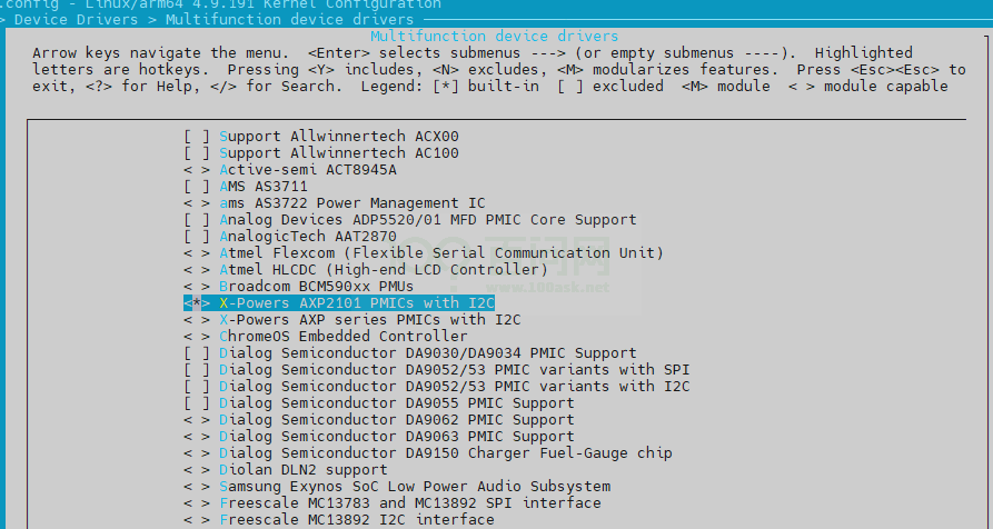
图2-1: pmu-control-config
• regulator
-> Device Drivers -> Voltage and Current Regulator Support <*> X-POWERS AXP2101 PMIC Regulators
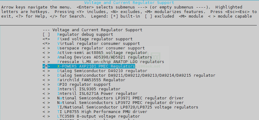
图2-2: regularot-config
• charger
-> Device Drivers -> Power supply class support <*> AXP2202 power supply driver
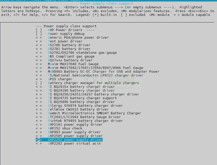
图2-3: charger-config
• power key
-> Device Drivers -> Input device support -> Miscellaneous devices <*> X-Powers AXP2101 power button driver
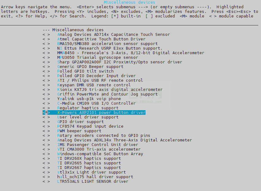
图2-4: power-key-config
• virtual regulator
-> Device Drivers -> Voltage and Current Regulator Support <*> Virtual regulator consumer support
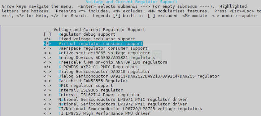
图2-5: virtuaal-config
• acin
-> Device Drivers -> Power supply class support < > AXP2202 power virtual acin
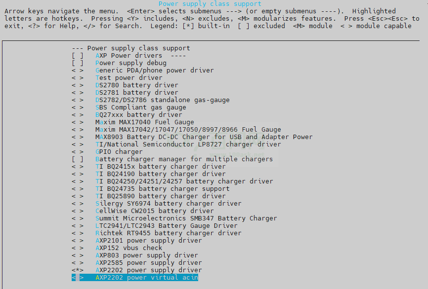
图2-6: acin-config
2.4 源码结构介绍
• AXP717
${ROOT_DIR}/lichee/{KERNEL_VERSION}/ drivers/mfd/axp2101.c drivers/mfd/axp2101-i2c.c drivers/regulator/axp2101-regulator.c drivers/input/misc/axp2101-pek.c drivers/power/supply/axp2202_battery.c drivers/power/supply/axp2202_charger.c drivers/power/supply/axp2202_gpio_power.c drivers/power/supply/axp2202_usb_power.c
2.5 模块框架介绍
AXP 的多功能设备驱动采用i2c 总线跟主控进行交互,使用regmap 方式注册访问接口。将AXP按照功能抽象出数个子设备模块,共同使用父设备axp mfd 的资源
(bus、irq)。基本的软件结构图如下图所示。
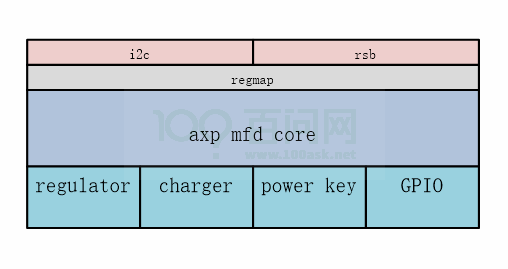
图2-7: AXP 框架图
将axp 按照功能划分为几个子设备,分别是regulator、charger、powe key、gpio。每个子设备作为一个cell,使用父设备的资源(bus,irq),与不同的内核子
系统交互,实现完整的电源管理功能。
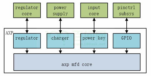
图2-8: AXP 软件框架图
不同款的AXP 型号功能框架也会是不一致的,详情各个型号的功能列表如下表所示。
| 产品名称 | regulator | charger | power key | gpio |
|---|---|---|---|---|
| AXP717 | 有 | 有 | 有 | 无 |
3 模块使用范例
3.1 外部sysfs 节点
AXP 注册了许多外部sysfs 节点可供调试使用。
3.1.1 Regulator
有关于regulator 调试节点,主要调整各路电压输出的。
在路径/sys/class/regulator/ 下,有关于单路regulator 属性的节点可以读取数值。
| 文件路径 | 功能 | 属性 | 设置值 |
|---|---|---|---|
| regulator.X/name | 各路输出名字 | r | 对应的输出的名字 |
| regulator.X/max_microvolts | 各路输出最大电压 | r | 对应的最大电压值,单位 uV |
| regulator.X/min_microvolts | 各路输出最小电压 | r | 对应的最小电压值,单位 uV |
| regulator.X/state | 各路输出状态 | r | 对应的输出状态, enabled/disabled: 开 启关闭 |
| regulator.X/num_users | 各路输出对应的设备个数 | r | 012…… |
因为不同AXP 型号regulator 对应的节点不一样,因此下面将分开不同AXP 进行介绍。
• AXP717
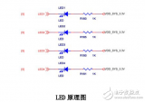
电源名称对应表如下:
| 节点名字 | 原理图名称 |
|---|---|
| regulator.0 | dummy |
| regulator.1 | usb0-vbus |
| regulator.2 | usb1-vbus |
| regulator.3 | dcdc1 |
| regulator.4 | dcdc2 |
| regulator.5 | dcdc3 |
| regulator.6 | dcdc4 |
| regulator.7 | aldo1 |
| regulator.8 | aldo2 |
| regulator.9 | aldo3 |
| regulator.10 | aldo4 |
| regulator.11 | bldo1 |
| regulator.12 | bldo2 |
| regulator.13 | bldo3 |
| regulator.14 | bldo4 |
| regulator.15 | cldo1 |
| regulator.16 | cldo2 |
| regulator.17 | cldo3 |
| regulator.18 | cldo4 |
| regulator.19 | rtcldo |
| regulator.20 | cpusldo |
| regulator.21 | drivevbus |
3.1.2 Virtual-consumer
在路径/sys/devices/platform/soc/7081400.s_twi/i2c-6/6-0034/ 下则有修改regulator 输出电压的节点。
| 文件路径 | 功能 | 属性 | 设置值 |
|---|---|---|---|
| reg-virtconsumer. X/max_microvolts | 设置输出最大电压 | rw | 对应的最大电压值,单 位uV |
| reg-virtconsumer. X/min_microvolts | 设置输出最小电压 | rw | 对应的最小电压值,单 位uV |
| of_node/name | 各路输出名字 | r | 无 |
因为不同AXP 型号Virtual-consumer 对应的节点不一样,因此下面将分开不同AXP 进行介绍。
• AXP717
virt-consumer 对应的电路的对应表如下:
| 节点名字 | 原理图名称 |
|---|---|
| reg-virt-consumer.1 | dcdc1 |
| reg-virt-consumer.2 | dcdc2 |
| reg-virt-consumer.3 | dcdc3 |
| reg-virt-consumer.4 | dcdc4 |
| reg-virt-consumer.5 | aldo1 |
| reg-virt-consumer.6 | aldo2 |
| reg-virt-consumer.7 | aldo3 |
| reg-virt-consumer.8 | aldo4 |
| reg-virt-consumer.9 | bldo1 |
| reg-virt-consumer.10 | bldo2 |
| reg-virt-consumer.11 | bldo3 |
| reg-virt-consumer.12 | bldo4 |
| reg-virt-consumer.13 | cldo1 |
| reg-virt-consumer.14 | cldo2 |
| reg-virt-consumer.15 | cldo3 |
| reg-virt-consumer.16 | cldo4 |
| reg-virt-consumer.17 | rtcldo |
| reg-virt-consumer.18 | cpusldo |
3.1.3 Power_supply
在路径/sys/class/power_supply/ 下有power_supply 相关的调试节点,可以读出电池以及供电当前状态和设置属性。
下表是电池相关的调试节点,路径为:/sys/class/power_supply/axp2202-battery/
| 文件路径 | 功能 | 属性 | 设置值 |
|---|---|---|---|
| capacity | 电池剩余电量 | r | 百分比,012……100 |
| capacity_alert_min | 低电量警告阈值 | r | 百分比 |
| capacity_level | 当前充电等级 | r | “UNKNOWN” 未知, “Critical” 接近没电,“LOW” 低 电量,“NORMAL” 正常电量, “HIGH” 高电量,“FULL” 满电 |
| charge_counter | 当前电池容量 | r | 单位mAh |
| charge_full | 充满电的电池容量 | r | 单位mAh |
| constant_charge_current | 恒定充电电流 | r | 单位mA |
| energy_full_design | 充满电的电池容量 | r | 单位mAh |
| health | 电池状况 | r | “Unknown” 未知, “Good” 好, “Overheat” 过温, “Dead” 坏掉, “Over voltage” 过 压,“Unspecified failure” 错误, “Cold” 冷 |
| present | 电池存在 | r | 01:存在不存在 |
| serial_number | pmu 型号 | r | string |
| status | 电池当前状态 | r | “Unknown” 未知, “Charging” 正在充电, “Discharging” 放电, “Not charging” 未在充电, “Full” 满 |
| temp | 电池温度 | r | 单位°C |
| temp_alert_min | 电池高温预警阈值 | r | 单位°C |
| time_to_empty_now | 放电剩余时间 | r | 单位min |
| time_to_full_now | 充电剩余时间 | r | 单位min |
| type | 设备类别 | r | “battery” 电池,“Mains” 火 牛,“USB”USB |
| voltage_now | 当前电压 | r | 单位uA |
下表则是供电相关的节点,路径为:/sys/class/power_supply/axp2202-usb
| 文件路径 | 功能 | 属性 | 设置值 |
|---|---|---|---|
| input_current_limit | 输入电流限流值 | r | 单位mA |
| online USB | 是否在使用 | r | 01:未使用正在使用 |
| present USB | 是否接上 | r | 01:插上没插上 |
| serial_number | pmu | 型号r | string |
| type | 设备类别 | r | “battery” 电 池,“Mains” 火 牛,“USB”USB |
| voltage_min_design | DC 供电最小设计电压 | r | 单位uV |
| voltage_now | DC 供电时的电压大小 | r | 单位uV |
说明
AXP717 没有使用acin,因此接入usb 或者适配器都是使用usb-power-supply 的驱动,节点也是公用的。
3.2 Regulator 使用方法
3.2.1 内核代码调用regulator 示例
以DCDC1 为例,需要设置DCDC1 最大输出电压值为3.4V,需要设置目标电压值为3V。
#include struct regulator *regu= NULL; int ret = 0; regu= regulator_get(NULL, "axp2202_dcdc1"); if (IS_ERR(regu)) { pr_err("%s: some error happen, fail to get regulator n", __func__); goto exit; } //set output voltage to 3V ret = regulator_set_voltage(regu, 3000000, 3400000); if (0 != ret) { pr_err("%s: some error happen, fail to set regulator voltage!n", __func__); goto exit; } //enalbe regulator ret = regulator_enable(regu); if (0 != ret) { pr_err("%s: some error happen, fail to enable regulator!n", __func__); goto exit; } //disalbe regulator ret = regulator_disable(regu); if (0 != ret) { pr_err("%s: some error happen, fail to disable regulator!n", __func__); goto exit; } //put regulater, when module exit regulator_put(regu);
技巧 regulator_get 调用有两种方法: 第一种就是直接获取dts 中regulator 的句柄,比如说axp2202_dcdc1。调用regulator_get 时第一个参数不需要配置设备,直接写NULL。 第二种是在dts 的设备里配置regulator 的节点,比如说dts 某个设备里配置regulator0 = "axp2202_dcdc1";,该设备调用时写法为:regulator_get(dev, "regulator0");。
3.2.2 Regulator shell 命令使用示例
AXP regulator 可以通过shell 命令控制和设置其开关以及输出电压,各路文件节点建立在在/sys/devices/platform 目录下
• AXP717
AXP717 可控的节点可参考上面virtual 章节Virtual-consumer
以设置DCDC1 输出最大电压为3.3V,设置目标电压为3.0V 为例做说明。
cd /sys/devices/platform/soc/7081400.s_twi/i2c-6/6-0034/reg-virt-consumer.1 cat of_node/name //确认是否为DCDC1 //设置输出电压为3.0V echo 3300000 > max_microvolts echo 3000000 > min_microvolts //关闭输出 echo 3300000 > max_microvolts echo 3000000 > min_microvolts echo 0 > min_microvolts
3.2.3 usb_count 查看
根据上面Regulator 章节Regulator 找到对应的regulator 节点,这里以dcdc1 为例,其节点名称为regulator.3,则在/sys/class/regulator 目录下就有个
regulator.3 目录,regulator.3目录有个num_users 节点,cat 此节点就可以获得当前use_count 值。
cat /sys/class/regulator/regulator.3/num_users
num_uesrs 代表当前有多少设备使用了regulator 节点用来控制输出电压。
4 FAQ
4.1 调试方法
在设备进行开发过程中,难免需要对各路电源进行调试,控制电源各路电压等操作,内核中提供了对电源调试的方式。
4.1.1 调试工具
4.1.1.1 power key 调试方式
在用户空间调用getevent 命令,通过标准input 系统上报的input 事件,可以确认power key是否能正常工作,是否能正常上报input 事件。
add device 2: /dev/input/event1 name: "axp2202-pek" poll 4, returned 1 /dev/input/event1: 0001 0074 00000001 poll 4, returned 1 /dev/input/event1: 0000 0000 00000000 poll 4, returned 1 /dev/input/event1: 0001 0074 00000000 poll 4, returned 1 /dev/input/event1: 0000 0000 00000000 poll 4, returned 1 /dev/input/event1: 0001 0074 00000001 poll 4, returned 1 /dev/input/event1: 0000 0000 00000000 poll 4, returned 1 /dev/input/event1: 0001 0074 00000000 poll 4, returned 1 /dev/input/event1: 0000 0000 00000000
按下按钮为1,弹起为0。0074 为power 事件。
4.1.2 调试节点
4.1.2.1 /sys/kernel/debug/regulator/regulator_summary 节点
shell 命令查询regulator 状态。
kernel 提供调试结点供电源进行调试进行,我们可以通过kernel 的调试结点获取各路电源的各个详细状态。以AXP2101 的设备举例,首先需要mount debugfs 文
件系统。
mount -t debugfs none /sys/kernel/debug cat /sys/kernel/debug/regulator/regulator_summary regulator use open bypass voltage current min max ------------------------------------------------------------------------------- regulator-dummy 0 8 0 0mV 0mA 0mV 0mV dmic 0mV 0mV uart2 0mV 0mV uart1 0mV 0mV twi3 0mV 0mV twi2 0mV 0mV twi1 0mV 0mV twi0 0mV 0mV twi6 0mV 0mV usb0-vbus 0 0 0 5000mV 0mA 5000mV 5000mV usb1-vbus 1 2 0 5000mV 0mA 5000mV 5000mV 5200000.ohci1-controller 0mV 0mV 5200000.ehci1-controller 0mV 0mV axp2202-dcdc1 0 2 0 900mV 0mA 500mV 1540mV cpu0 900mV 900mV reg-virt-consumer.1 0mV 0mV axp2202-dcdc2 0 1 0 950mV 0mA 500mV 3400mV reg-virt-consumer.2 0mV 0mV axp2202-dcdc3 0 1 0 1200mV 0mA 500mV 1840mV reg-virt-consumer.3 0mV 0mV axp2202-dcdc4 0 1 0 1000mV 0mA 1000mV 3700mV reg-virt-consumer.4 0mV 0mV axp2202-aldo1 0 3 0 2800mV 0mA 500mV 3500mV sensor1 2800mV 3300mV sensor0 2800mV 3300mV reg-virt-consumer.5 0mV 0mV axp2202-aldo2 1 4 0 1800mV 0mA 500mV 3500mV sensor1 1800mV 3300mV sensor0 1800mV 3300mV sensor0 1800mV 3300mV reg-virt-consumer.6 0mV 0mV axp2202-aldo3 0 1 0 3300mV 0mA 500mV 3500mV reg-virt-consumer.7 0mV 0mV axp2202-aldo4 0 2 0 1800mV 0mA 500mV 3500mV codec 1800mV 1800mV reg-virt-consumer.8 0mV 0mV axp2202-bldo1 2 3 0 3300mV 0mA 500mV 3500mV soc@03000000:wlan@0 3300mV 3300mV soc@03000000:wlan@0 3300mV 3300mV reg-virt-consumer.9 0mV 0mV axp2202-bldo2 0 1 0 2500mV 0mA 500mV 3500mV reg-virt-consumer.10 0mV 0mV axp2202-bldo3 1 1 0 2800mV 0mA 500mV 3500mV reg-virt-consumer.11 0mV 0mV axp2202-bldo4 0 3 0 1500mV 0mA 500mV 3500mV sensor1 1500mV 1800mV sensor0 1200mV 1800mV reg-virt-consumer.12 0mV 0mV axp2202-cldo1 3 3 0 1800mV 0mA 500mV 3500mV codec 1800mV 1800mV 1-0036 1800mV 1800mV axp2202-cldo2 0 1 0 3300mV 0mA 500mV 3500mV reg-virt-consumer.14 0mV 0mV axp2202-cldo3 3 4 0 3300mV 0mA 500mV 3500mV 1-0036 3300mV 3300mV sdc2 0mV 0mV uart0 0mV 0mV reg-virt-consumer.15 0mV 0mV axp2202-cldo4 0 1 0 3300mV 0mA 500mV 3500mV reg-virt-consumer.16 0mV 0mV axp2202-rtcldo 0 1 0 1800mV 0mA 1800mV 1800mV reg-virt-consumer.17 0mV 0mV axp2202-cpusldo 0 1 0 900mV 0mA 500mV 1400mV reg-virt-consumer.18 0mV 0mV axp2202-drivevbus 0 0 0 0mV 0mA 0mV 0mV
4.1.2.2 regmap registers 节点
shell 命令读写寄存器。
寄存器调试是指直接对PMIC 的寄存器进行读写操作,此操作应该对寄存器有了解的情况下进行操作,不正确的操作方式将会导致芯片烧毁。在终端中,对抛出的
调试结点进行读写操作,即可对寄存器进行读写操作。无论是读还是写寄存器,都应该首先挂载debugfs 文件系统。
由于PMIC 是通过regmap 进行读写操作,应该可以使用regmap 的调试结点进行对PMIC 的读写访问操作。regmap 的调试结点在debugfs 文件系统下面,通过对
regmap 调试结点的操作可以对PMIC 的寄存器进行读写访问操作。
• 写操作
寄存器调试挂载在debugfs文件系统。 mount -t debugfs none /sys/kernel/debug echo ${reg} ${value} > /sys/kernel/debug/regmap/${dev-name}/registers 实例: echo 0xff 0x01 > /sys/kernel/debug/regmap/4-0034/registers 写0xff寄存器值为0x01
• 读操作
寄存器调试挂载在debugfs文件系统。 mount -t debugfs none /sys/kernel/debug cat /sys/kernel/debug/regmap/${dev-name}/registers 实例: cat /sys/kernel/debug/regmap/4-0034/registers 读取pmic所有寄存器
4.1.2.3 axp_reg 节点
另外,还支持axp 驱动自定义节点axp_reg 读写寄存器。但是这种用法是不推荐的,因为有标准regmap 方式来读写寄存器,根本没必要用私有非标的方式。示例
如下。
往axp寄存器0x0f写入值0x55: echo 0x0f55 > /sys/class/axp/axp_reg 读出axp寄存器0x0f的值: echo 0x0f > /sys/class/axp/axp_reg cat /sys/class/axp/axp_reg
4.1.2.4 debug_mask 节点
axp 驱动自定义节点debug_mask 打开和关闭调试信息。相关调试信息参考具体的PMIC 驱动。示例如下。
系统打印等级设置为8: echo 8 > /proc/sys/kernel/printk 打开所有axp调试信息: echo 0xf > /sys/class/axp/debug_mask 关闭所有axp调试信息: echo 0x0 > /sys/class/axp/debug_mask
调试信息一般如下。
[ 712.458412] ic_temp = 45 [ 712.461311] vbat = 3977 [ 712.464082] ibat = -779 [ 712.466280] healthd: battery l=96 v=3977 t=30.0 h=2 st=3 c=-779 fc=5066880 chg= [ 712.475174] charge_ibat = 0 [ 712.478448] dis_ibat = 779 [ 712.481545] ocv = 4073 [ 712.484239] rest_vol = 96 [ 712.487182] rdc = 123 [ 712.489862] batt_max_cap = 5066 [ 712.493472] coulumb_counter = 4857 [ 712.497583] AXP803_COULOMB_CTL = 0xe0 [ 712.501803] ocv_percentage = 86 [ 712.505436] col_percentage = 96 [ 712.509061] bat_current_direction = 0 [ 712.513386] ext_valid = 0
-
soc
+关注
关注
40文章
4635浏览量
230272 -
Linux
+关注
关注
88文章
11821浏览量
219598 -
开发指南
+关注
关注
0文章
48浏览量
7929 -
PMU
+关注
关注
1文章
127浏览量
23430 -
Tina
+关注
关注
2文章
45浏览量
17748
发布评论请先 登录
Tina_Linux系统裁剪开发指南
Rockchip Linux SDK uboot logo开发指南

Tina Linux图形系统开发指南

Tina Linux Wi-Fi开发指南


评论