 DS1390/DS1391 RTC与带SPI的摩托罗拉DSP接口

本应用笔记介绍如何将DS1390连接至内置SPI™接口模块的摩托罗拉DSP。该电路使用摩托罗拉DSP56F800DEMO演示板和CodeWarrior® IDE。
描述
DS1390实时时钟(RTC)可通过SPI接口与微控制器(μC)或数字信号处理(DSP)单元连接。本应用笔记介绍如何将DS1390连接至内置SPI接口模块的摩托罗拉DSP。该电路使用摩托罗拉DSP56F800DEMO演示板和CodeWarrior IDE。
使用示例软件
示例软件是从空白项目开始开发的。按照摩托罗拉套件安装指南(教程:创建 CodeWarrior 项目)中的说明进行操作,了解详细信息。在main.c中添加本应用笔记中包含的代码。
操作
该程序使用GPIO端口来控制DS1390上的CS。软件初始化SPI控制器模块,DSP将时间和日期写入DS1390。然后,软件循环读取时间和日期。DS1390和DS1391支持SPI模式1和3。
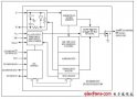
电路原理图如图1所示。该电路包括连接到摩托罗拉演示板的子卡。请注意,图1中的电路包括几个带SPI接口的RTC。一次只能使用一个RTC,软件仅支持DS1390。该软件如图 2 所示。
图1.
图 2.子卡示意图。
图3.代码清单
/* File: DS1390.c */
/* This example program was developed using the Motorola
56F800 Demo Board Kit.  Follow the kit instalation guide
for creating a CodeWarrior Project.  Use the shell of the
new project for this example.  Note: This program is for
example only and is not supported by Dallas Semiconductor
Maxim. */

#include "port.h"
#include "stdio.h"
#include "stdlib.h"

/*******************************************************
* Main program for use with Embedded SDK
*******************************************************/

extern sampleASM (void);

void reset_spi(void);
void wbyte_spi(unsigned char);
void init_sci0(Word16);
tx_sci0(unsigned char);
void bcd2ascii(unsigned char);
unsigned char  rbyte_spi(void);

#define REG_BASE 0x0000
#define SCI0_BASE 0x0F00
#define SPI_BASE 0x0F20
#define GPIOA_BASE 0x0FB0
#define GPIOB_BASE 0x0FC0

#define SCI0_SCIBR *(volatile UWord16 *)(SCI0_BASE + 0)
#define SCI0_SCICR *(volatile UWord16 *)(SCI0_BASE + 1)
#define SCI0_SCISR *(volatile UWord16 *)(SCI0_BASE + 2)
#define SCI0_SCIDR *(volatile UWord16 *)(SCI0_BASE + 3)

#define SPSCR *(volatile UWord16 *)(SPI_BASE + 0)
#define SPDSR *(volatile UWord16 *)(SPI_BASE + 1)
#define SPDRR *(volatile UWord16 *)(SPI_BASE + 2)
#define SPDTR *(volatile UWord16 *)(SPI_BASE + 3)

#define GPIO_A_PUR *(volatile UWord16 *)(GPIOA_BASE + 0)
#define GPIO_A_DR *(volatile UWord16 *)(GPIOA_BASE + 1)
#define GPIO_A_DDR *(volatile UWord16 *)(GPIOA_BASE + 2)
#define GPIO_A_PER *(volatile UWord16 *)(GPIOA_BASE + 3)

#define GPIO_B_PUR *(volatile UWord16 *)(GPIOB_BASE + 0)
#define GPIO_B_DR *(volatile UWord16 *)(GPIOB_BASE + 1)
#define GPIO_B_DDR *(volatile UWord16 *)(GPIOB_BASE + 2)
#define GPIO_B_PER *(volatile UWord16 *)(GPIOB_BASE + 3)

void main (void)
{
unsigned char   msec=0, min=0x26, sec=0x00, hr=0x17, dow=0x06,
                                date=0x26, mon=0x12, yr=0x03, write = 0;

        reset_spi();
        init_sci0(195);                 // 30MHz / 195 = 9600 baud

        GPIO_B_DR = 0x0008;             // disable RTC - CS high

        GPIO_B_DR = 0;                  // enable RTC - CS low
        wbyte_spi(0x8d);                // control register write address
        rbyte_spi();                    // dummy read
        wbyte_spi(0x18);                // enable osc, 32kHz sqw
        rbyte_spi();
        GPIO_B_DR = 0x0008;             // disable RTC - CS high

        if(write)
        {
                GPIO_B_DR = 0;                  // enable RTC - CS low
                wbyte_spi(0x80);                // select seconds register write address
                rbyte_spi();                    // dummy read
                wbyte_spi(msec);                // milliseconds register data
                rbyte_spi();
                wbyte_spi(sec);                 // seconds register data
                rbyte_spi();
                wbyte_spi(min);                 // minutes register
                rbyte_spi();
                wbyte_spi(hr);                  // hours register
                rbyte_spi();
                wbyte_spi(dow);                 // day of week register
                rbyte_spi();
                wbyte_spi(date);                // date register
                rbyte_spi();
                wbyte_spi(mon);                 // month register
                rbyte_spi();
                wbyte_spi(yr);                  // year register
                rbyte_spi();
                GPIO_B_DR = 0x0008;             // disable RTC - CS high
        }
        while(1)
        {
                GPIO_B_DR = 0u;                 // enable RTC - CS low

                wbyte_spi(0);                   // seconds register read address
                rbyte_spi();                    // dummy read
                wbyte_spi(0);
                msec = rbyte_spi();             // read milliseconds register
                wbyte_spi(0);
                sec = rbyte_spi();              // read seconds register
                wbyte_spi(0);
                min = rbyte_spi();              // ditto minutes
                wbyte_spi(0);
                hr = rbyte_spi();               // and so on
                wbyte_spi(0);
                dow = rbyte_spi();
                wbyte_spi(0);
                date = rbyte_spi();
                wbyte_spi(0);
                mon = rbyte_spi();
                wbyte_spi(0);
                yr = rbyte_spi();

                GPIO_B_DR = 0x0008;             // disable RTC - CS high

                tx_sci0(0x0d);                  // sequence to print time & date
                tx_sci0(0x0a);
                bcd2ascii(yr);
                tx_sci0('/');
                bcd2ascii(mon);
                tx_sci0('/');
                bcd2ascii(date);
                tx_sci0(' ');
                bcd2ascii(hr);
                tx_sci0(':');
                bcd2ascii(min);
                tx_sci0(':');
                bcd2ascii(sec);
        }

        return;
}

//SPSCR
//15 14  13   12     11   10    9     8    7       6       5    4        3    2    1    0
// r MSB SPRF ERRIE  ovrf modf spte modfen spr1   spr0   sprie spmstr   cpol cpha spe  spite

void reset_spi()
{
int     val;
        SPSCR = 0x0056; // SPR0, SPMSTR, CPHA, SPE
        SPDSR = 0x0007; // 8-bit size

        SPSCR &= 0xfffd;        // clear spe, resets SPI (partial)
        SPSCR |= 0x0002;        // set spe, new values take effect

        GPIO_B_PER = 0x00f3;    // use GPIOB3 as CS for RTC
        GPIO_B_DDR = 0x000d;    // direction is output

        GPIO_A_PER = 0x00f9;    // enable/disable per function (1=enable)
        GPIO_A_DDR = 0x0006;    // direction is output (1=output)
        GPIO_A_DR  = 0;                 // write bits low (0=low)
}

void  wbyte_spi( unsigned char  wbyte)  // ------ write one byte -------
{
        while (!(SPSCR & 0x0200));  // wait for transmitter empty flag

        SPDTR = wbyte;
}

void    bcd2ascii(unsigned char dat)    // ----- convert bcd to ascii and send to sci ----
{
        tx_sci0( (dat >> 4) + 0x30);
        tx_sci0( (dat & 0x0f) + 0x30);
}
unsigned char rbyte_spi(void)   // -------- read one byte ----------
{
        while (!(SPSCR & 0x2000));  // wait for receiver full flag

        return(SPDRR);

}

void    init_sci0(Word16 baud)
{
        GPIO_B_PER = 0x00f3;    // set up
        GPIO_B_DDR = 0x000d;    // direction is output

        SCI0_SCIBR = baud;              // baud rate
        SCI0_SCICR = 0x2000;    // control reg
}
tx_sci0(unsigned char val)
{
UWord16 reg;

        SCI0_SCICR &= 0xfffb;   // turn receiver off
        SCI0_SCICR |= 8;                // turn transmitter on
        do
        {
                reg = SCI0_SCISR;               // clear flag by reading
        }       while( (reg & 0x8000) == 0);    // wait until RDRF is false

        SCI0_SCIDR = (unsigned int) (val);
}
审核编辑:郭婷
声明:本文内容及配图由入驻作者撰写或者入驻合作网站授权转载。文章观点仅代表作者本人,不代表电子发烧友网立场。文章及其配图仅供工程师学习之用,如有内容侵权或者其他违规问题,请联系本站处理。
举报投诉
-
dsp
+关注
关注
559文章
8214浏览量
363976 -
控制器
+关注
关注
114文章
17638浏览量
190258 -
GPIO
+关注
关注
16文章
1313浏览量
55727
发布评论请先 登录
相关推荐
热点推荐
DS1390/DS1391/DS1394 pdf datas
The low-voltage serial-peripheral interface (SPI™)DS1390/DS1391/DS1394 and the low-vol
发表于 08-10 10:35
•42次下载
DS1392, DS1393,pdf datasheet (
The low-voltage serial-peripheral interface (SPI™) DS1390/DS1391/DS1394 and the low-vo
发表于 09-03 07:51
•28次下载
Interfacing a DS1390/DS1391 RT
This app note shows how to connect a DS1390 to a Motorola DSP that has a built-in SPIinterface
发表于 04-25 10:21
•18次下载
Interfacing a DS1390/DS1391 RT
Processing (DSP) unit using a SPI interface. This app note shows how to connect a DS1390 to a Motorola
发表于 05-29 08:37
•11次下载
DS1390/DS1391 RTC与Motorola SPI
摘要:本应用笔记说明了DS1390与内置SPI™接口的Motorola DSP的连接方式,该电路使用了Motorola DSP5
发表于 04-21 11:10
•1748次阅读

摩托罗拉Wilder正式发布
目前已有众多传闻称,摩托罗拉公司将于本月推出其全新高端智能手机——摩托罗拉Droid 3。不过在摩托罗拉Droid 3正式亮相前,摩托罗拉公司则为我们带来了一款入门级手机——
发表于 06-10 18:13
•1044次阅读
DS1390-DS1394低电压SPI/3线接口RTC
低电压串行外设接口(SPI™) DS1390/DS1391/DS1394和低电压3线DS1392
发表于 11-15 11:56
•3502次阅读
DS1390-DS1394数据资料
The low-voltage serial-peripheral interface (SPI)DS1390/DS1391/DS1394 and the low-voltage
发表于 11-15 12:09
•40次下载


 工商网监
工商网监
评论