 DISCO-F746NG探索套件让扩展能力大幅提升

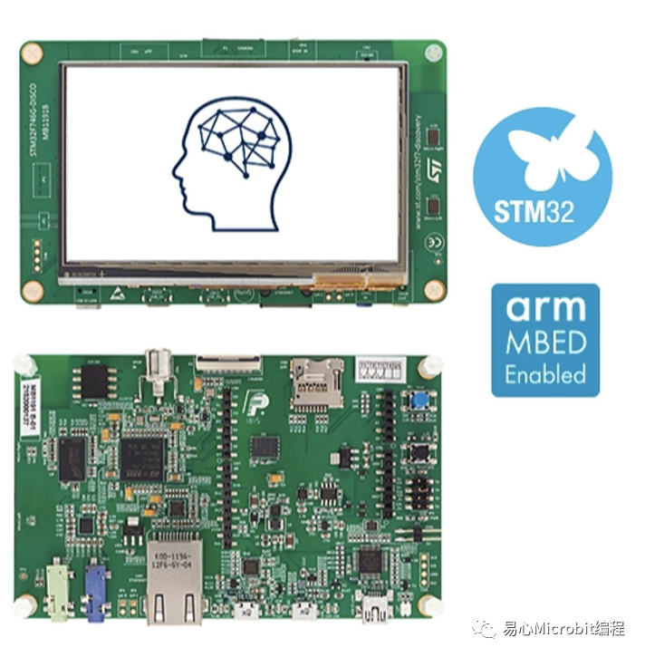
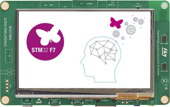
笔者最近取得一个有趣的套件,是国内开发者不陌生的STM32系列之一的IoT开发工具包- STM32F746G-DISCOVERY(DISCO-F746NG)探索套件。它的功能相当完整,其运算核心是基于 Arm Cortex-M7 的 STM32F746NG微控制器,具备强大的运算能力。它同时整合了4.3吋的彩色电容式触控屏幕、USB OTG、Audio Codec、Micro SD 插槽、双数字麦克风,也内建以太网络10/100Mb来延伸网络应用,从而简化应用程序的开发,能快速验证产品与想法。
继承STM32的优良传统,此套件也支持易于开发的Arduino IDE环境,让原本使用Arduino的Maker可以快速上手,更可以直接使用兼容于Arduino开源函式库,共享相关社群的开发资源。不仅如此,这个套件提供兼容于ARDUINO Uno V3的扩充插槽,让扩展能力大幅提升。
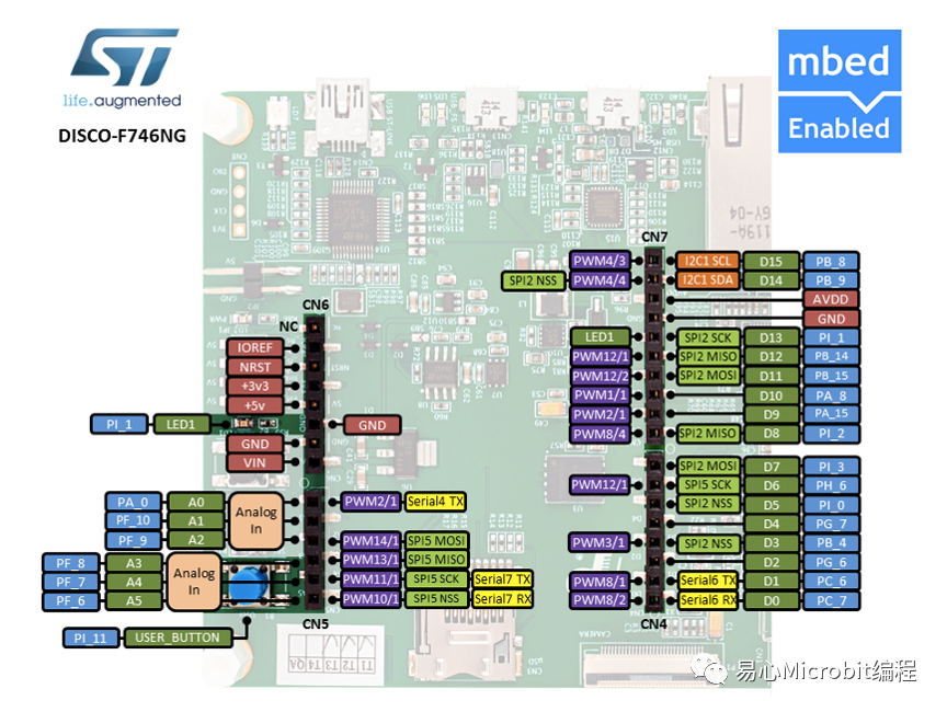
本开发板引出的GPIO如下图:
Arduino 开发环境安装
看到这样强大的功能与完善的支持接口,你是不是和笔者一样跃跃欲试了呢?别急,先把Arduino开发环境安装起来吧。
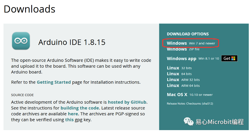
(1) 请先下载Arduino IDE开发环境
https://www.arduino.cc/en/software
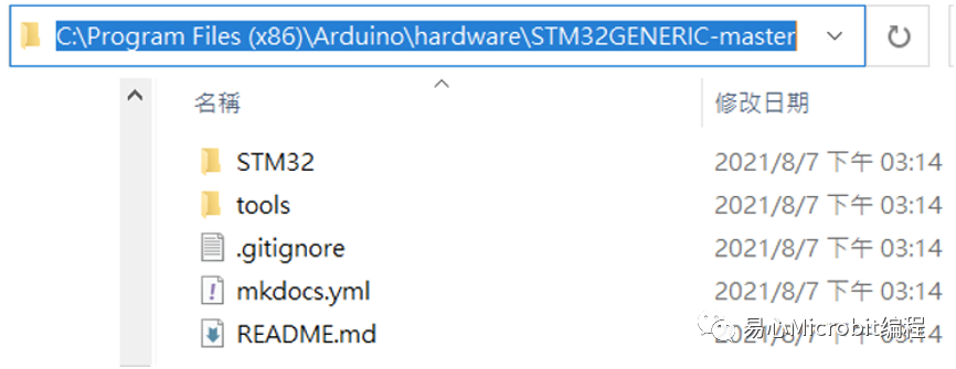
(2) 为Arduino IDE安装STM32的支持,从Github下载最新的版本,解压缩至
C:Program Files (x86)Arduinohardware
https://github.com/fw-box/STM32GENERIC
(注:这个路径依照你的Arduino安装路径可能略有不同)
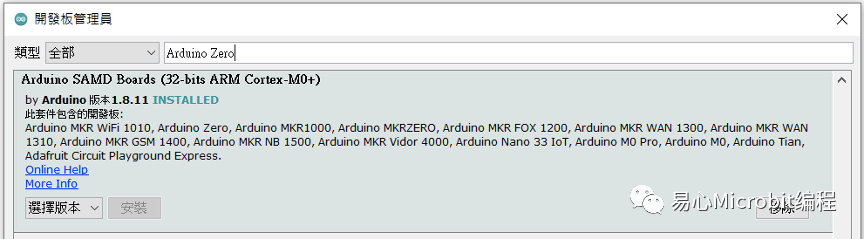
(3) 安装编译程序arm-none-eabi-gcc,从开发板管理员搜寻并安装Arduino SAMD Boards (32-bits Arm Cortex-M0+) 版本1.8.11
(4) 编译STM32GENERIC时会有错误,请使用patch档覆写arm-none-eabi-gcc里的原始码,共有4个档会被覆写。
Patch文件下载路径:
https://github.com/fw-box/arm-none-eabi
解压缩并覆写到
C:UsersmynameAppDataLocalArduino15packagesarduino oolsarm-none-eabi-gcc7-2017q4arm-none-eabi
(注:myname要改成你的使用者名称)
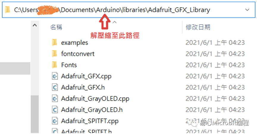
(5) 下载下列4个必需的函式库并解压缩至
C:UsersmynameDocumentsArduinolibraries
(注:myname要改成你的使用者名称)
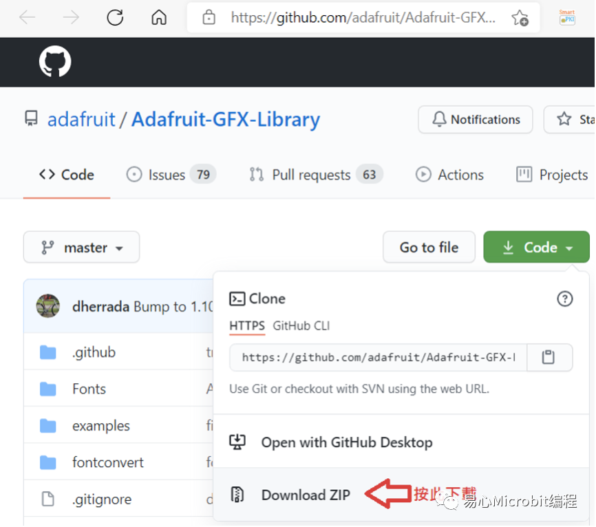
https://github.com/adafruit/Adafruit-GFX-Library
https://github.com/fw-box/Adafruit_BusIO
https://github.com/stm32duino/LwIP
https://github.com/fw-box/STM32Ethernet
下载方法如下图,下载下来会是一个压缩文件。解压缩一个新的函式库至libraries后,需要重新启动Arduino IDE来扫描加载新的函式库。
下载并安装开发板的驱动程序
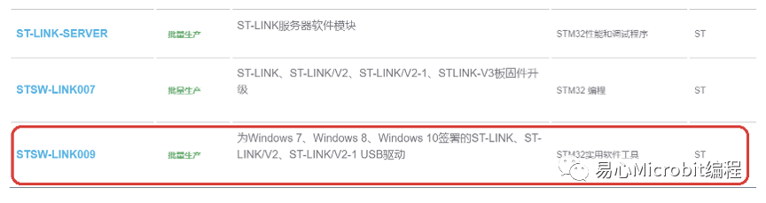
请到ST官网介绍此套件的「工具与软件」区,找到ST-LINK驱动程序,
https://www.st.com/zh/evaluation-tools/32f746gdiscovery.html?fbclid=IwAR2Kjh0Qf59IpkKOTpz7iNKo6AX13nPNFPWxFGhgnGSilr07reN2-XJTyZU#tools-software
按下下图红框内的连结后会跳出注册画面,注册后www.st.com会发送下载的网址到注册信箱。下载后解压缩,并以系统管理员身份执行stlink_winusb_install.bat安装驱动程序。
编译刻录设定
选择开发板Discovery F746NG;Upload method改成Mass Storage:
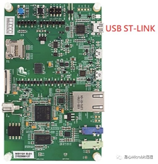
开始上传(刻录)前,请用mini USB线连接PC与开发板的USB ST-LINK。然后把串行端口改成新出现的COM port,上图的范例是COM20。
程序范例
安装好了,我们来执行几个程序范例吧。
1. 数位GPIO read, write
这功能与一般Arduino模式一样,按钮USER_BTN是背面的蓝色按钮,可供用户自定义功能。
LED_BUILTIN在黑色按钮旁边,范例程序运作后会开始闪烁,按下蓝色按钮后闪烁速度会变快。
1. void setup()
2. {
3. pinMode(USER_BTN, INPUT);
4. pinMode(LED_BUILTIN, OUTPUT);
5. }
6.
7. void loop()
8. {
9. digitalWrite( LED_BUILTIN , HIGH ); // led on
10.
11. if ( digitalRead( USER_BTN ) )
12. delay(10); // blink faster if button is pressed
13. else
14. delay(100);
15.
16. digitalWrite( LED_BUILTIN, LOW ); // led off
17. delay(100);
18. }
程序代码来源 : UserButton.ino
https://github.com/danieleff/STM32GENERIC/blob/master/STM32/libraries/BoardExamples/examples/Discovery746NG/UserButton/UserButton.ino
2. ADC读取
此套件ADC的分辨率最高为12 bits,数值范围是0 ~ 4096。为保持与Arduino UNO的兼容性,A0 ~ A5皆有被定义,可以直接使用。程序代码中P开头的GPIO名是为本开发板所定义,A0可以用PA0取代、A1可以用PF10取代,其它GPIO对应如程序代码所示。此范例会不断地把A0读到的数值写到串行端口,请开启串行端口监控窗口查看结果。
// thesetup routine runs once when you press reset:
2. void setup() {
3. // initialize serial communication at115200 bits per second:
4. Serial.begin(115200);
5. delay(1000);
6.
7. // configure the ADC for 12 Bits
8. analogReadResolution(12);
9.
10. Serial.println();
11. Serial.printf("PA0:%d, A0:%d ",PA0, A0);
12. Serial.printf("PF10:%d, A1:%d ",PF10, A1);
13. Serial.printf("PF9:%d, A2:%d ",PF9, A2);
14. Serial.printf("PF8:%d, A3:%d ",PF8, A3);
15. Serial.printf("PF7:%d, A4:%d ",PF7, A4);
16. Serial.printf("PF6:%d, A5:%d ",PF6, A5);
17. }
18.
19. //the loop routine runs over and over again forever:
20. voidloop() {
21. // read the input on analog pin 0:
22. int sensorValue = analogRead(PA0);
23. // print out the value you read:
24. Serial.printf("PA0=%d ",sensorValue);
25. delay(1000); // delay in between reads forstability
26. }
程序代码来源 : AnalogtReadSerial_12bit.ino
https://github.com/danieleff/STM32GENERIC/blob/master/STM32/libraries/BoardExamples/examples/Discovery746NG/AnalogtReadSerial_12bit/AnalogtReadSerial_12bit.ino
3. 使用SDRAM
DISCO-F746NG拥有8MB(64 Mbits)可用的SDRAM,但系统会用掉一些,所以无法完整配置8MB内存。下列程序代码是配置7MB的内存的范例。
1. voidsetup()
2. {
3. Serial.begin(115200);
4. }
5. void loop()
6. {
7. uint32_t size = 7 * 1024 * 1024; // 7MB
8. Serial.printf("Allocating %dbuffer ", size);
9.
10. uint8_t *data = (uint8_t*)malloc(size);
11. if (data == NULL)
12. Serial.println("Mallocfailed!");
13. else
14. Serial.println("Success");
15.
16. free(data);
17. delay(5000);
18. }
I2C存取
请把I2C模块的SCL、SDA接至下面的脚位– I2C1_SCL、I2C1_SDA,记得模块的3V3、GND也要接上。
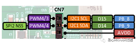
以下程序会扫描出模块的I2C地址。请注意在呼叫Wire.begin();之前要先呼叫Wire.stm32SetInstance(I2C1); Wire.stm32SetSDA(PB9);Wire.stm32SetSCL(PB8); 来设定I2C连接的脚位,因为DISCO-F746NG拥有4组I2C(I2C1 ~ I2C4),对应到Arduino UNO扩充插槽I2C脚位的是I2C1。
#include
2.
3. void setup()
4. {
5. Wire.stm32SetInstance(I2C1);
6. Wire.stm32SetSDA(PB9);
7. Wire.stm32SetSCL(PB8);
8. Wire.begin();
9.
10. Serial.begin(115200);
11. delay(5000);
12. Serial.println(" I2C Scanner");
13. }
14.
15. voidloop()
16. {
17. byte error, address;
18. int nDevices;
19.
20. Serial.println("Scanning...");
21. delay(2000);
22.
23. nDevices = 0;
24. for (address = 1; address < 127;address++ ) {
25. // The i2c_scanner uses the return valueof
26. // the Write.endTransmisstion to see if
27. // a device did acknowledge to theaddress.
28. Wire.beginTransmission(address);
29. Wire.write(0);
30. error = Wire.endTransmission();
31.
32. if (error == 0) {
33. Serial.print("I2C device found ataddress 0x");
34. if (address < 16) Serial.print("0");
35. Serial.print(address, HEX);
36. Serial.println(" !");
37. nDevices++;
38. }
39. else if (error == 4) {
40. Serial.print("no device found ataddress 0x");
41. if (address < 16)Serial.print("0");
42. Serial.println(address, HEX);
43. }
44. }
45. if (nDevices == 0) {
46. Serial.println("No I2C devicesfound ");
47. Serial.println("Did you configure thechip select for your device? ");
48. }
49. else
50. Serial.println("done ");
51.
52. delay(5000); // wait 5 seconds for next scan
53. }
程序代码修改自 : I2cScanner.ino
https://github.com/danieleff/STM32GENERIC/blob/master/STM32/libraries/BoardExamples/examples/all_boards/I2cScanner/I2cScanner.ino
绘图与触控屏幕
触控IC接在I2C3的位置,所以要先做I2C的初始化。因为篇幅的关系,仅列出主程序,请从Github取得stm32_ub_touch_480x272.h与stm32_ub_touch_480x272.cpp,与主程序放在同一个目录。
https://github.com/danieleff/STM32GENERIC/tree/master/STM32/libraries/BoardExamples/examples/Discovery746NG/TFT/TouchDisplay
1. #include
2. #include "stm32_ub_touch_480x272.h"// 触控屏幕
3. #include "LTDC_F746_Discovery.h" //绘图
4.
5. LTDC_F746_Discovery tft;
6.
7. uint8_t UB_I2C3_ReadByte(uint8_taddressI2cDevice, uint8_t registerId)
8. {
9. uint8_t result;
10. addressI2cDevice = addressI2cDevice>> 1;
11.
12. Wire.beginTransmission(addressI2cDevice );
13. Wire.write( registerId );
14. uint8_t error;
15. error = Wire.endTransmission();
16.
17. Wire.requestFrom( addressI2cDevice,(uint8_t) 1 , (uint8_t) true );
18.
19. while ( Wire.available() < 1 );
20.
21. result = Wire.read() ;
22.
23. if (error)Serial.println("I2Cerror");
24.
25. return result;
26. }
27.
28. voidsetup()
29. {
30. Serial.begin(115200);
31. delay(1000);
32.
33. Wire.stm32SetInstance(I2C3);
34. Wire.stm32SetSDA(PH8);
35. Wire.stm32SetSCL(PH7);
36.
37. Wire.begin();
38.
39. UB_Touch_Init();
40.
41. // The buffer is memory mapped
42. // You can directly draw on the display bywriting to the buffer
43. uint16_t *buffer = (uint16_t*)malloc(2*LTDC_F746_ROKOTECH.width * LTDC_F746_ROKOTECH.height);
44.
45. tft.begin((uint16_t *)buffer);
46. tft.fillScreen(LTDC_WHITE);
47. }
48.
49. voidloop()
50. {
51. UB_Touch_Read();
52.
53. int x = Touch_Data.xp;
54. int y = Touch_Data.yp;
55.
56. Serial.printf("(%d, %d) ", x, y);
57. tft.fillCircle(x, y, 3, LTDC_BLUE);
58.
59. delay(10);
60. }
程序代码修改自 : TouchDisplay.ino
https://github.com/danieleff/STM32GENERIC/blob/master/STM32/libraries/BoardExamples/examples/Discovery746NG/TFT/TouchDisplay/TouchDisplay.ino
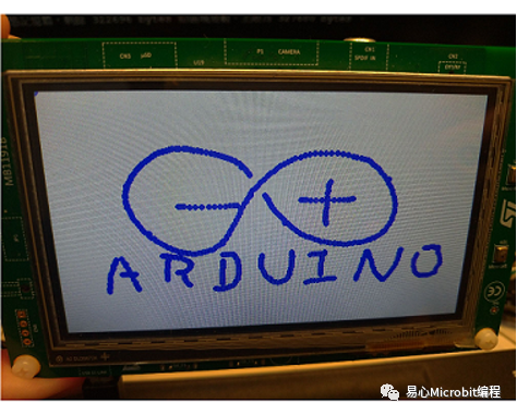
程序执行画面,用手指在触控屏幕上画图,类似小画家的效果。
透过Ethernet连接至因特网
以下是一个使用HTTP GET联机至http://example.com的范例,执行后会把Server的响应显示在串行端口监控窗口。
1. #include
2. #include
3.
4. EthernetClient client;
5.
6. // random MAC address
7. byte mac[] = { 0xDE, 0xAD, 0xBE, 0xEF, 0xFE,0xED };
8.
9. void setup() {
10. Serial.begin(115200);
11.
12. Serial.println("Connecting toEthernet");
13.
14. if (!Ethernet.begin(mac)) {
15. Serial.println("ERROR: Could notconnect to ethernet!");
16. while(1);
17. }
18.
19. Serial.println("Connecting toexample.com");
20.
21. if (!client.connect("example.com",80)) {
22. Serial.println("ERROR: Could notconnect to example.com!");
23. while(1);
24. }
25.
26. Serial.println("Connected, sendingrequest");
27.
28. client.println("GET /HTTP/1.1");
29. client.println("Host:example.com");
30. client.println();
31. client.flush();
32.
33. Serial.println("Request sent,printing response");
34. }
35.
36. voidloop() {
37. if (client.available()) {
38. char c = client.read();
39. Serial.print(c);
40. }
41.
42. if (!client.connected()) {
43. Serial.println();
44.Serial.println("disconnecting.");
45. client.stop();
46. while (1);
47. }
48. }
更多范例
可以从以下位置找到更多范例:
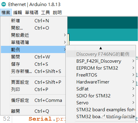
Arduino ID选单的档案=>范例=>DiscoveryF746NG的范例
结语
DISCO-F746NG使用Arm架构的M7微控制器,效能强大,运作起来相当流畅,而且本身已经具备彩色触控屏幕、Audio、麦克风与Ethernet,不用再另外接模块。笔者测试过其触控定位功能,相当精准且反应快速,很适合担任显示与人机互动的主机。再加上它支持易入门的Arduino IDE,开发者可在网络上找到很多参考数据,不怕碰到问题时搜寻不到解决方法。
看完本文的介绍,你是不是发现这个套件相当适合来实现你心中「某个」创意的原型设计呢?
-
微控制器
+关注
关注
49文章
8909浏览量
166036 -
以太网
+关注
关注
41文章
6291浏览量
181923 -
Arduino
+关注
关注
191文章
6534浏览量
197658 -
套件
+关注
关注
0文章
22浏览量
22407
原文标题:上手DISCO-F746NG探索套件,Arduino也兼容!
文章出处:【微信号:易心Microbit编程,微信公众号:易心Microbit编程】欢迎添加关注!文章转载请注明出处。
发布评论请先 登录
stm32f746g-disco显示白屏的原因有哪些?
转:将STM32F746G-Disco开发板做助听器
STM32F746Disco开发板的MicroPython固件
STM32F746G-DISCO是什么
如何开始使用STM32F746G-DISCO?
Discovery_kit_for_STM32F7_Series_with_STM32F746NG_MCU
微雪电子32F746GDISCOVERY STM32F7开发板简介
基于STM32F746G-DISCO微控制器的参考设计


评论