 如何使用PIC微控制器和脉搏传感器进行心跳监测

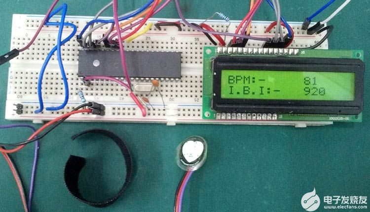
心跳率是监测任何人健康状况的最重要参数。在可穿戴设备的现代时代,有很多设备可以测量心跳、血压、脚步声、燃烧的卡路里和许多其他东西。这些设备内部有脉冲传感器来感应脉搏率。今天,我们还将使用带有PIC微控制器的脉冲传感器来计算每分钟的心跳次数和心跳间隔,这些值将进一步显示在16x2字符LCD上。我们将在本项目中使用PIC16F877A PIC微控制器。我们已经将脉冲传感器与Arduino连接起来,用于患者监测系统。
必需组件
PIC16F877A 微控制器
20 兆赫晶体
33pF电容 2个
4.7k 电阻器 1 个
16x2 字符液晶显示器
10K 电位器,用于 LCD 的对比度控制
SEN-11574 脉冲传感器
魔术贴带
5V电源适配器
面包板和连接线
脉冲传感器 SEN-11574
为了测量心跳,我们需要一个脉搏传感器。在这里,我们选择了SEN-11574脉冲传感器,它可以在网上或线下商店轻松买到。我们使用此传感器是因为制造商提供了示例代码,但那是Arduino代码。我们为PIC微控制器转换了该代码。
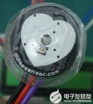
该传感器非常小,非常适合通过耳垂或指尖读取心跳。它的直径为 0.625“,圆形 PCB 侧的厚度为 0.125”。
该传感器提供模拟信号,传感器可由3V或5V驱动,传感器的电流消耗为4 mA,非常适合移动应用。传感器配有三根电线,末端带有 24 英寸长的连接电缆和 berg 公接头。此外,传感器还配有魔术贴指带,可将其佩戴在指尖上。
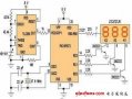
脉冲传感器原理图也由制造商提供,也可在 sparkfun.com 上购买。
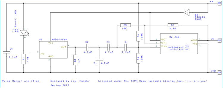
传感器原理图由光学心率传感器、降噪RC电路或滤波器组成,如原理图所示。R2、C2、C1、C3 和运算放大器 MCP6001 用于可靠的放大模拟输出。
用于心跳监测的其他传感器很少,但SEN-11574脉冲传感器广泛用于电子项目。
脉冲传感器与PIC微控制器接口的电路图
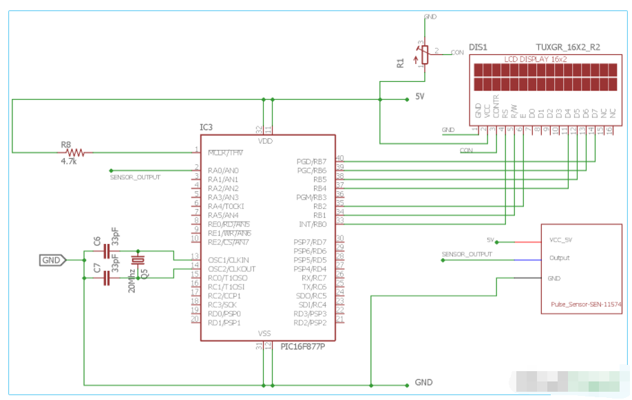
在这里,我们已经连接了脉冲传感器跨 2德·微控制器的引脚单位。由于传感器提供模拟数据,我们需要通过进行必要的计算将模拟数据转换为数字信号。
20Mhz的晶体振荡器通过两个陶瓷33pF电容器连接在微控制器单元的两个OSC引脚上。液晶屏通过微控制器的RB端口连接。
PIC16F877A 心跳监护仪代码说明
对于初学者来说,代码有点复杂。制造商提供了SEN-11574传感器的示例代码,但它是为Arduino平台编写的。我们需要转换微芯片 PIC16F877A 的计算结果。本项目结束时将提供完整的代码,并附有演示视频。并且可以从此处下载支持的C文件。
我们的代码流相对简单,我们使用开关大小写来执行步骤。根据制造商的说法,我们需要每 2 毫秒从传感器获取数据。因此,我们使用了计时器中断服务例程,它将每 2 毫秒触发一个函数。
switch语句中的代码流将如下所示:
案例1:读取ADC
案例2:计算心跳和IBI
情况 3:在液晶屏上显示心跳和 IBI
案例 4:空闲(不执行任何操作)
在定时器中断功能中,我们将程序的状态更改为情况 1:每 2 毫秒读取一次 ADC。
因此,在 main 函数中,我们定义了程序状态和所有开关情况。
void main() {
system_init();
main_state = READ_ADC;
while (1) {
switch (main_state) {
case READ_ADC:
{
adc_value = ADC_Read(0); // 0 is the channel number
main_state = CALCULATE_HEART_BEAT;
break;
}
case CALCULATE_HEART_BEAT:
{
calculate_heart_beat(adc_value);
main_state = SHOW_HEART_BEAT;
break;
}
case SHOW_HEART_BEAT:
{
if (QS == true) { // A Heartbeat Was Found
// BPM and IBI have been Determined
// Quantified Self "QS" true when Arduino finds a heartbeat
QS = false; // reset the Quantified Self flag for next time
// 0.9 used for getting better data. actually should not be used
BPM = BPM * 0.9;
IBI = IBI / 0.9;
lcd_com(0x80);
lcd_puts("BPM:- ");
lcd_print_number(BPM);
lcd_com(0xC0);
lcd_puts("I.B.I:- ");
lcd_print_number(IBI);
}
}
main_state = IDLE;
break;
case IDLE:
{
break;
}
default:
{
}
}
}
}
我们使用 PIC16F877A 的两个硬件外设:定时器0 和 ADC。
在 timer0.c 文件中,
TMR0 = (uint8_t)(tmr0_mask & (256-(((2 *_XTAL_FREQ)/(256*4))/1000)));
此计算提供 2 毫秒计时器中断。计算公式为
// TimerCountMax - (((delay(ms) * Focs(hz)) / (PreScale_Val * 4)) / 1000)
如果我们看到timer_isr函数,它是-
void timer_isr() {
main_state = READ_ADC;
}
在此函数中,程序状态每 2ms 更改为 READ_ADC。
然后,CALCULATE_HEART_BEAT函数取自 Arduino 示例代码。
void calculate_heart_beat(int adc_value) {
Signal = adc_value;
sampleCounter += 2; // keep track of the time in mS with this variable
int N = sampleCounter - lastBeatTime; // monitor the time since the last beat to avoid noise
// find the peak and trough of the pulse wave
if (Signal < thresh && N > (IBI / 5)*3) { // avoid dichrotic noise by waiting 3/5 of last IBI
if (Signal < T) { // T is the trough
T = Signal; // keep track of lowest point in pulse wave
}
}
………….
………………………..
此外,下面给出了完整的代码,并通过注释进行了很好的解释。这种心跳传感器数据可以进一步上传到云端,并从任何地方通过互联网进行监控,从而使其成为基于物联网的心跳监测系统。
/*
* File: main.c
* Author: Sourav Gupta
* By:- circuitdigest.com
* Created on September 30, 2018, 2:26 PM
*/
// PIC16F877A Configuration Bit Settings
// 'C' source line config statements
// CONFIG
#pragma config FOSC = HS // Oscillator Selection bits (HS oscillator)
#pragma config WDTE = OFF // Watchdog Timer Enable bit (WDT disabled)
#pragma config PWRTE = OFF // Power-up Timer Enable bit (PWRT disabled)
#pragma config BOREN = ON // Brown-out Reset Enable bit (BOR enabled)
#pragma config LVP = OFF // Low-Voltage (Single-Supply) In-Circuit Serial Programming Enable bit (RB3/PGM pin has PGM function; low-voltage programming enabled)
#pragma config CPD = OFF // Data EEPROM Memory Code Protection bit (Data EEPROM code protection off)
#pragma config WRT = OFF // Flash Program Memory Write Enable bits (Write protection off; all program memory may be written to by EECON control)
#pragma config CP = OFF // Flash Program Memory Code Protection bit (Code protection off)
#include
#include
#include
#include
#include
#include "supporing_cfilelcd.h"
#include "supporing_cfileeusart1.h"
#include "supporing_cfileadc.h"
#include "supporing_cfiletmr0.h"
/*
Hardware related definition
*/
#define _XTAL_FREQ 200000000 //Crystal Frequency, used in delay
/*
Program Flow related definition
*/
#define READ_ADC 1
#define CALCULATE_HEART_BEAT 2
#define SHOW_HEART_BEAT 3
#define IDLE 0
#define DEFAULT -1
volatile int rate[10]; // array to hold last ten IBI values
volatile unsigned long sampleCounter = 0; // used to determine pulse timing
volatile unsigned long lastBeatTime = 0; // used to find IBI
volatile int P = 512; // used to find peak in pulse wave, seeded
volatile int T = 512; // used to find trough in pulse wave, seeded
volatile int thresh = 530; // used to find instant moment of heart beat, seeded
volatile int amp = 0; // used to hold amplitude of pulse waveform, seeded
volatile bool firstBeat = true; // used to seed rate array so we startup with reasonable BPM
volatile bool secondBeat = false; // used to seed rate array so we startup with reasonable BPM
volatile int BPM; // int that holds raw Analog in 0. updated every 2mS
volatile int Signal; // holds the incoming raw data
volatile int IBI = 600; // int that holds the time interval between beats! Must be seeded!
volatile bool Pulse = false; // "True" when User's live heartbeat is detected. "False" when not a "live beat".
volatile bool QS = false; // becomes true when finds a beat.
int main_state = -1;
int adc_value = 0;
int tune = 0;
/*
Other Specific definition
*/
void system_init(void);
void calculate_heart_beat(int adc_value) {
Signal = adc_value;
sampleCounter += 2; // keep track of the time in mS with this variable
int N = sampleCounter - lastBeatTime; // monitor the time since the last beat to avoid noise
// find the peak and trough of the pulse wave
if (Signal < thresh && N > (IBI / 5)*3) { // avoid dichrotic noise by waiting 3/5 of last IBI
if (Signal < T) { // T is the trough
T = Signal; // keep track of lowest point in pulse wave
}
}
if (Signal > thresh && Signal > P) { // thresh condition helps avoid noise
P = Signal; // P is the peak
} // keep track of highest point in pulse wave
// NOW IT'S TIME TO LOOK FOR THE HEART BEAT
// signal surges up in value every time there is a pulse
if (N > 250) { // avoid high frequency noise
if ((Signal > thresh) && (Pulse == false) && (N > (IBI / 5)*3)) {
Pulse = true; // set the Pulse flag when we think there is a pulse
IBI = sampleCounter - lastBeatTime; // measure time between beats in mS
lastBeatTime = sampleCounter; // keep track of time for next pulse
if (secondBeat) { // if this is the second beat, if secondBeat == TRUE
secondBeat = false; // clear secondBeat flag
int i;
for (i = 0; i <= 9; i++) { // seed the running total to get a realisitic BPM at startup
rate[i] = IBI;
}
}
if (firstBeat) { // if it's the first time we found a beat, if firstBeat == TRUE
firstBeat = false; // clear firstBeat flag
secondBeat = true; // set the second beat flag
//pulse_tmr_handle = bsp_harmony_start_tmr_cb_periodic(PULSE_CHECK_TIME_INTERVAL, 0, pulse_read_cb); // enable interrupts again
return; // IBI value is unreliable so discard it
}
// keep a running total of the last 10 IBI values
uint16_t runningTotal = 0; // clear the runningTotal variable
int i;
for (i = 0; i <= 8; i++) { // shift data in the rate array
rate[i] = rate[i + 1]; // and drop the oldest IBI value
runningTotal += rate[i]; // add up the 9 oldest IBI values
}
rate[9] = IBI; // add the latest IBI to the rate array
runningTotal += rate[9]; // add the latest IBI to runningTotal
runningTotal /= 10; // average the last 10 IBI values
BPM = 60000 / runningTotal; // how many beats can fit into a minute? that's BPM!
QS = true; // set Quantified Self flag
// QS FLAG IS NOT CLEARED INSIDE THIS ISR
}
}
if (Signal < thresh && Pulse == true) { // when the values are going down, the beat is over
Pulse = false; // reset the Pulse flag so we can do it again
amp = P - T; // get amplitude of the pulse wave
thresh = amp / 2 + T; // set thresh at 50% of the amplitude
P = thresh; // reset these for next time
T = thresh;
}
if (N > 2500) { // if 2.5 seconds go by without a beat
thresh = 530; // set thresh default
P = 512; // set P default
T = 512; // set T default
lastBeatTime = sampleCounter; // bring the lastBeatTime up to date
firstBeat = true; // set these to avoid noise
secondBeat = false; // when we get the heartbeat back
}
}
void main() {
system_init();
main_state = READ_ADC;
while (1) {
switch (main_state) {
case READ_ADC:
{
adc_value = ADC_Read(0);
main_state = CALCULATE_HEART_BEAT;
break;
}
case CALCULATE_HEART_BEAT:
{
calculate_heart_beat(adc_value);
main_state = SHOW_HEART_BEAT;
break;
}
case SHOW_HEART_BEAT:
{
if (QS == true) { // A Heartbeat Was Found
// BPM and IBI have been Determined
// Quantified Self "QS" true when arduino finds a heartbeat
QS = false; // reset the Quantified Self flag for next time
// 0.9 used for getting better data. actually should not be used
//BPM = BPM * 0.9;
// IBI = IBI / 0.9;
//IBI = IBI * 2;
// tune = BPM / 2;
//lcd_com(0x01);
lcd_com(0x80);
lcd_puts("BPM:- ");
lcd_print_number(BPM);
lcd_puts (" ");
lcd_com(0xC0);
lcd_puts("I.B.I:- ");
lcd_print_number(IBI);
lcd_puts (" ");
}
}
main_state = IDLE;
break;
case IDLE:
{
break;
}
default:
{
}
}
}
}
/*
This Function is for system initializations.
*/
void system_init(void){
TRISB = 0x00;
lcd_init(); // This will initialize the lcd
TMR0_Initialize();
TMR0_StartTimer();
INTERRUPT_GlobalInterruptEnable();
INTERRUPT_PeripheralInterruptEnable();
ADC_Init();
}
/*
* Custom timer callback function
*/
void timer_isr() {
main_state = READ_ADC;
}
void interrupt INTERRUPT_InterruptManager (void)
{
// interrupt handler
if(INTCONbits.TMR0IE == 1 && INTCONbits.TMR0IF == 1)
{
TMR0_ISR();
}
}
-
微控制器
+关注
关注
48文章
8249浏览量
162263 -
传感器
+关注
关注
2573文章
54357浏览量
785767 -
PIC
+关注
关注
8文章
511浏览量
90424
发布评论请先 登录
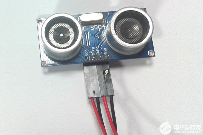
如何将超声波传感器HC-SR04与PIC微控制器连接
基于JN5139的ZigBee无线传感器网络体温脉搏监测系统
玩的就是心跳 | 用 PulseSensor 脉搏传感器测心率
MAX1169 ADC与PIC微控制器的接口

PIC微控制器技术及应用 1-12章
PIC微控制器技术及应用 13-23章
PIC微控制器技术及应用 24-29章
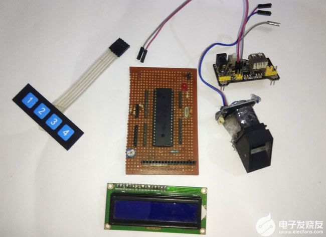
如何将指纹传感器与PIC微控制器连接


 工商网监
工商网监
评论