 设计一个宠物NFC定时喂食器

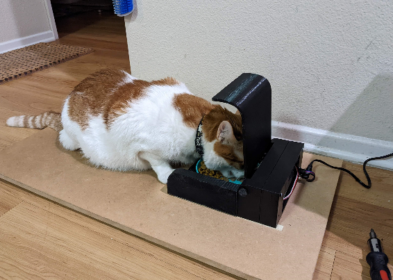
我设计并制造了这款自动猫喂食器,以帮助我的糖尿病猫控制他的喂食并防止我的另一只猫吃他的食物。该喂食器可能对需要监控宠物喂食需求的其他宠物主人有用。
我的猫需要药食以及每日的胰岛素剂量,他经常会骗我们喂他两次,或者另一只猫会吃他的食物,这让我们很难知道他到底吃了多少。
我想创建一个封闭的喂食器,它可以检测到哪只猫在喂食器上,然后为正确的猫打开。我的第一个想法是在他们的项圈上使用 NFC 标签,以便区分它们。然而,NFC 标签的有效接近是有问题的,因为它们仅在标签的几毫米内激活。经过其他几个想法,包括读取它们背后的微芯片,我决定区分我的两只猫的最简单方法是通过重量。
我在 Instructables 上找到了一个使用 Arduino Uno 创建浴室秤的项目,在成功构建该项目后,我决定创建这个项目。秤精确到十分之一磅,但您的动物会移动很多,因此我们将尝试区分大约半磅或四分之一公斤。
在确定这个解决方案之前,我创建了一个原型并经历了十几个或更多的设计想法。
这是一个中等难度的项目。它需要使用一些基本的电动工具、焊接、大量的 3D 打印、打磨和粘合。提供了项目的所有代码以及如何修改代码的说明。
补给品
所需工具:3D 打印机、电脑、钻头、烙铁、螺丝刀套装、钳子、尖嘴钳、砂纸、Dremel 工具(可选)、热风枪、氰基丙烯酸酯液体胶、钢锯、电压表。
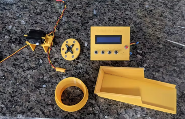
第 1 步:3D 打印
从称重传感器支架开始打印所有自定义组件。您将需要 4 个称重传感器底座和顶部。
第 2 步:计重秤构建
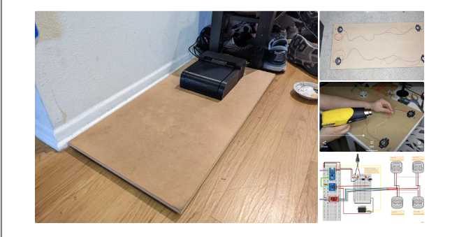
使用 MDF 等材料将您的体重秤底座切割成您喜欢的任何尺寸。我的是 30” x 15” (76cm x 38cm),进纸器本身是 ~7” x 8.5” (18cm x 21.5cm)
使用称重传感器安装座作为四个角的引导预钻孔。标出哪个称重传感器是哪个(左上角、左下角等)会很有帮助。
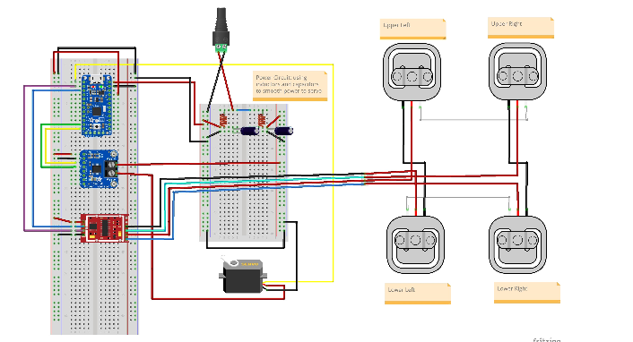
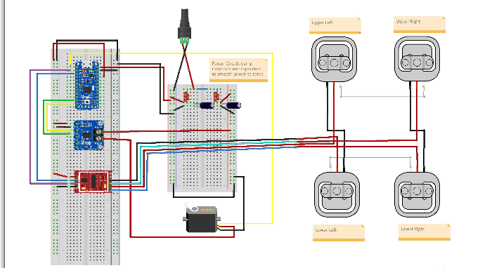
使用图中的接线图
1) 连接称重传感器线对
2)将电线剪成一定长度
3) 在使用剥线钳拆下外壳并将线对绞在一起之前,将热缩套管放在电线上。
将焊料涂在电线上,然后将热缩管移到连接处并加热。
连接线对后,您应该有四根松散的红线,每根线都来自一个称重传感器。您将使用四针母头 RGB 接头连接器。在左下称重传感器附近钻一个足够大的孔,以便电线穿过,其中红色圆圈如上图所示。接下来,按照图中的接线图,将红色电线焊接并热缩到正确颜色的电线上RGB 母头。您必须将正确的信号线连接到正确的颜色,否则您的秤将无法工作。将公连接器焊接到 HX711 上,这是接线图中的红色芯片,再次确保所有颜色的顺序正确。还将 4 个分接引脚焊接到标有 VCC、SCK、DT 和 GND 的孔上。
项目接线图-点击下载
第 3 步:秤校准和测试
下一步,您将需要面包板、Arduino Uno 和一些跳线。
Sparkfun 有很棒的 Arduino 程序来运行,最新版本可点击链接在 GitHub 上找到
第一个软件步骤是确定秤的校准系数。为此,请运行以下代码:
|
/* Example using the SparkFun HX711 breakout board with a scale By: Nathan Seidle SparkFun Electronics Date: November 19th, 2014 License: This code is public domain but you buy me a beer if you use this and we meet someday (Beerware license). This is the calibration sketch. Use it to determine the calibration_factor that the main example uses. It also outputs the zero_factor useful for projects that have a permanent mass on the scale in between power cycles. Setup your scale and start the sketch WITHOUT a weight on the scale Once readings are displayed place the weight on the scale Press +/- or a/z to adjust the calibration_factor until the output readings match the known weight Use this calibration_factor on the example sketch This example assumes pounds (lbs). If you prefer kilograms, change the Serial.print(" lbs"); line to kg. The calibration factor will be significantly different but it will be linearly related to lbs (1 lbs = 0.453592 kg). Your calibration factor may be very positive or very negative. It all depends on the setup of your scale system and the direction the sensors deflect from zero state This example code uses bogde's excellent library:"https://github.com/bogde/HX711" bogde's library is released under a GNU GENERAL PUBLIC LICENSE Arduino pin 2 -> HX711 CLK 3 -> DOUT 5V -> VCC GND -> GND Most any pin on the Arduino Uno will be compatible with DOUT/CLK. The HX711 board can be powered from 2.7V to 5V so the Arduino 5V power should be fine. */ #include "HX711.h" #define LOADCELL_DOUT_PIN 3 #define LOADCELL_SCK_PIN 2 HX711 scale; float calibration_factor = -7050; //-7050 worked for my 440lb max scale setup void setup() { Serial.begin(9600); Serial.println("HX711 calibration sketch"); Serial.println("Remove all weight from scale"); Serial.println("After readings begin, place known weight on scale"); Serial.println("Press + or a to increase calibration factor"); Serial.println("Press - or z to decrease calibration factor"); scale.begin(LOADCELL_DOUT_PIN, LOADCELL_SCK_PIN); scale.set_scale(); scale.tare(); //Reset the scale to 0 long zero_factor = scale.read_average(); //Get a baseline reading Serial.print("Zero factor: "); //This can be used to remove the need to tare the scale. Useful in permanent scale projects. Serial.println(zero_factor); } void loop() { scale.set_scale(calibration_factor); //Adjust to this calibration factor Serial.print("Reading: "); Serial.print(scale.get_units(), 1); Serial.print(" lbs"); //Change this to kg and re-adjust the calibration factor if you follow SI units like a sane person Serial.print(" calibration_factor: "); Serial.print(calibration_factor); Serial.println(); if(Serial.available()) { char temp = Serial.read(); if(temp == '+' || temp == 'a') calibration_factor += 10; else if(temp == '-' || temp == 'z') calibration_factor -= 10; |
校准秤后,您可以运行此示例程序,然后将其修改为您自己的目的:
|
/* Example using the SparkFun HX711 breakout board with a scale By: Nathan Seidle SparkFun Electronics Date: November 19th, 2014 License: This code is public domain but you buy me a beer if you use this and we meet someday (Beerware license). This example demonstrates basic scale output. See the calibration sketch to get the calibration_factor for your specific load cell setup. This example code uses bogde's excellent library:"https://github.com/bogde/HX711" bogde's library is released under a GNU GENERAL PUBLIC LICENSE The HX711 does one thing well: read load cells. The breakout board is compatible with any wheat-stone bridge based load cell which should allow a user to measure everything from a few grams to tens of tons. Arduino pin 2 -> HX711 CLK 3 -> DAT 5V -> VCC GND -> GND The HX711 board can be powered from 2.7V to 5V so the Arduino 5V power should be fine. */ |
按照本项目中的比例校准草图中,获取您的校准因子 ex为-9660.0 ,您将在后面的步骤中需要用到这个数据。
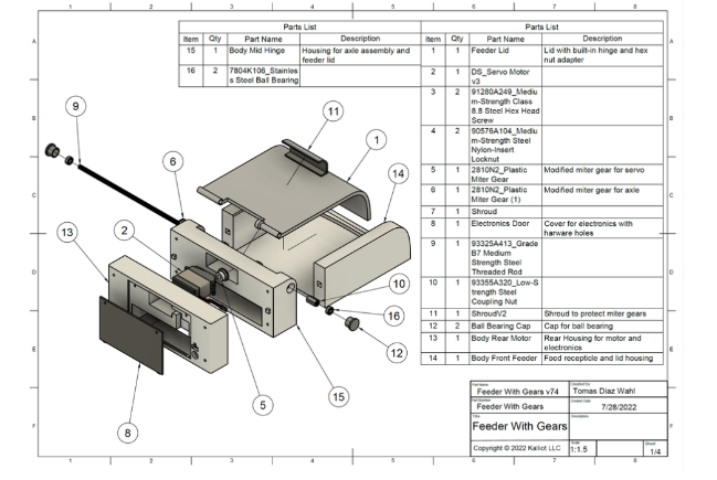
第 4 步:进纸器主体和盖子组件
第一步是将进纸器盖连接到车身中间铰链组件。您还需要塑料斜接齿轮轴、M5 连接螺母和 M5 螺纹杆。你要确保你的盖子适合铰链机构的翅片之间并有间隙,没有任何打嗝或擦伤。
确保您的连接螺母非常紧贴进料器盖上的六角连接器和塑料斜接齿轮。这里的舒适贴合非常重要,不应该有任何玩耍。接下来,使用钢锯或 Dremel 上的圆形切割钻头将螺纹杆切割成 18 厘米。确保去除切割表面的任何毛刺。将螺杆穿过组件。您可能想先尝试不使用连接螺母。如果杆无法插入或太紧,请小心地将孔钻出合适的尺寸。
如果组件自由移动,则该检查与进料器主体前部的间隙。将车身前送纸器的定位方块与车身中间铰链对齐,确保两个车身完全接触,没有间隙。配准方格应有助于防止错位 图 6. 升高和降低盖子以确保没有间隙或配合问题。如果间隙看起来不错,请从铰链组件上拆下杆并暂时搁置这些组件。
您现在将车身中间铰链粘到车身前端进纸器上。在每个粘合表面的中心涂抹极少量的液体氰基丙烯酸酯胶(超级胶水)。我强烈建议在蜡纸上这样做,因为您的打印件会粘在它上面的表面上。将两个组件牢牢按住并保持 30 秒。我们还可以将连接到 HX711 的桶形插头和公头 4 针 RGB 接头粘到车身后电机上。
当胶水固化时,您将塑料斜接齿轮伺服连接到伺服。为此,您将在伺服系统上的冠状齿轮的齿上加热形成斜接齿轮。将烤箱预热至华氏 160 度。取出烤盘,铺上一层羊皮纸。将斜接齿轮放在羊皮纸上,然后将其放在烤箱的顶部架子上。PLA 的玻璃化转变阶段在 50-80 摄氏度之间。如果您使用的是 ABS 或其他塑料,请获取该材料的玻璃化转变温度并相应地更改烤箱温度。当您的烤箱完成预热后,将斜接齿轮再放置大约三分钟。将斜接齿轮从烤箱中取出,快速但小心地将齿轮上的孔对准冠状齿轮上方并用力按下。这一步要轻柔,因为塑料现在变得柔韧且非常热,并且容易变形。将斜接齿轮留在齿轮上,直到其冷却,以避免热收缩或膨胀。
冷却后,用 M3 平头螺栓和垫圈固定斜接齿轮。将伺服器放入车身后电机并用四个 M5 x 30 螺栓固定。
车身中间铰链和车身前馈线现在粘合在一起,用馈线盖、六角螺母、斜接齿轮和 M5 杆重新组装铰链机构。将两个轴承放入轴承盖并将轴承盖安装到车身中铰链的孔中。您现在应该已组装好所有 3D 组件,除了齿轮的护罩和电子设备的门。
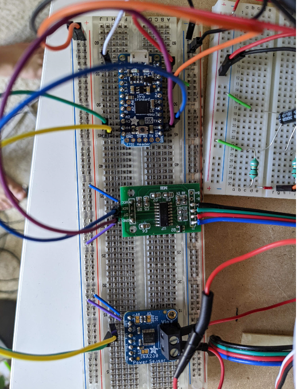
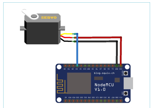
第 5 步:电子组装
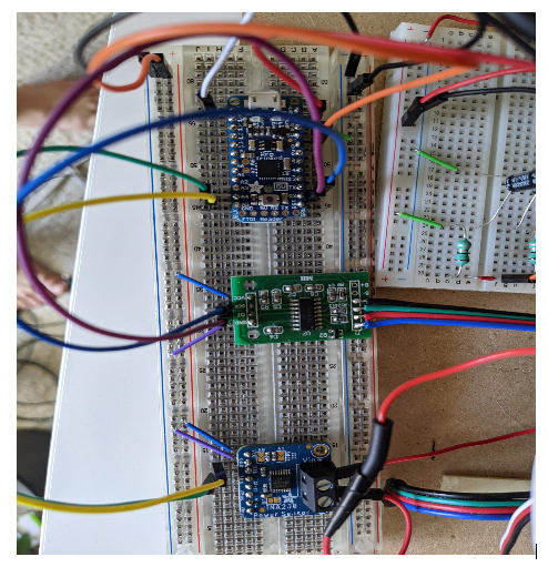
在这个阶段,我们将在面包板上组装电子设备,以确保我们所有的电子元件都按预期运行。按照图中搭建电源电路,但不要连接舵机的黄色信号线。电路的左侧是 Arduino 的电源,电路的右侧是伺服的电源。伺服系统的电源也通过 Adafruit INA260 电流和电压感应芯片运行,该芯片将充当我们的安全系统。如果您对组件通电时的电压正确感到满意,请完成芯片的接线,确保连接公头和母头 RGB 接头,这会将您的秤连接到进纸器。
第 6 步:编码和测试
/**
Developed for Hobbyiest use by Tomas Diaz-Wahl for Kalliot LLC.
Copyright © 2022 Kalliot LLC
Redistribution and use in source and binary forms, with or without modification, are permitted provided that the following
conditions are met:
1. Redistributions of source code and documentation must retain the above copyright notice, this list of conditions and the
following disclaimer.
2. Redistributions in binary form must reproduce the above copyright notice, this list of conditions and the following
disclaimer in the documentation and/or other materials provided with the distribution.
3. Neither the name of the copyright holder nor the names of its contributors may be used to endorse or promote products
derived from this software without specific prior written permission.
THIS SOFTWARE AND DOCUMENTATION ARE PROVIDED BY THE COPYRIGHT HOLDERS AND CONTRIBUTORS "AS IS" AND ANY EXPRESS OR IMPLIED WARRANTIES,
INCLUDING, BUT NOT LIMITED TO, THE IMPLIED WARRANTIES OF MERCHANTABILITY AND FITNESS FOR A PARTICULAR PURPOSE ARE
DISCLAIMED. IN NO EVENT SHALL THE COPYRIGHT HOLDER OR CONTRIBUTORS BE LIABLE FOR ANY DIRECT, INDIRECT, INCIDENTAL,
SPECIAL, EXEMPLARY, OR CONSEQUENTIAL DAMAGES (INCLUDING, BUT NOT LIMITED TO, PROCUREMENT OF SUBSTITUTE GOODS OR SERVICES;
LOSS OF USE, DATA, OR PROFITS; OR BUSINESS INTERRUPTION) HOWEVER CAUSED AND ON ANY THEORY OF LIABILITY, WHETHER IN CONTRACT,
STRICT LIABILITY, OR TORT (INCLUDING NEGLIGENCE OR OTHERWISE) ARISING IN ANY WAY OUT OF THE USE OF THIS SOFTWARE,
EVEN IF ADVISED OF THE POSSIBILITY OF SUCH DAMAGE.
**/
/*
* This project uses two third-party libraries.
* INA260 and HX711 libraries can be found at:
*
*
*/
#include
#include
#include "HX711.h"
Adafruit_INA260 ina260 = Adafruit_INA260();
Servo servo;
HX711 scale;
/*
* Debug class is designed to output info to the serial monitor, (found under the tools menu in the Arduino IDE),
* This is designed to make sure that all boards and electronics are working as designed.
* TO ACTIVATE DEBUG CLASS MAKE SURE debugOn IS SET TO TRUE.
*/
class Debug {
public:
static const bool debugOn = false; //turn debug on and off
void printMsg(int x){
if (debugOn){
Serial.print(x);
Serial.flush();
}
}
void printMsg(String x){
if (debugOn){
Serial.print(x);
Serial.flush();
}
}
void printLine(int x){
if (debugOn){
Serial.println(x);
Serial.flush();
}
}
void printLine(String x){
if (debugOn){
Serial.println(x);
Serial.flush();
}
}
void setUpSerial(){
if (debugOn){
Serial.begin(9600);
// Wait until serial port is opened
while (!Serial) { delay(10); }
}
}
};//Debug
/*
* Queue class is designed to make a basic queue for our current measurements.
* There is no need to modify this class.
*/
class Queue{
private:
const static int maxQueueSize = 8;
float arr [maxQueueSize];
int queuePos;
public:
Queue(){
for (int i = 0; i < maxQueueSize; i++)
{
arr[i] = 0;
}
queuePos = maxQueueSize - 1;
}// Queue constructor
int enqueue (float val){
queuePos += 1;
if (queuePos >= maxQueueSize){
queuePos = 0;
}
arr[queuePos] = val;
}
float getAvg (){
float total = 0;
float avg;
for (int i = 0; i < maxQueueSize; i++){
total += arr [i];
}
avg = total / maxQueueSize;
return avg;
}
};// class Queue
/*
* Feeder class allows for motion of the feeder lid as well as implementing a check
* to see if there is an obstruction affecting lid motion.
* You will need to change several variable in the private data section of this class.
* You MUST change: calibrationFactor, minCatWeight, maxCatWeight
* You MAY need to change: maxCurrent, lidMaxPosition, any pin designations you wish to change.
*/
class Feeder {
public:
const int moveAmount = 1; // How much the servo should move per command
/*
* Set up stores an known initial position in the microcontroller memory.
* Tells the microcontroller which pin the servo is on.
* Activates and sets the scale calibration factor (see SparkFun_HX711_Calibration sketch)
*/
void setUp () {
servo.write (initialPos);
servo.attach(servoPin);
delay (1000);
scale.begin(LOADCELL_DOUT_PIN, LOADCELL_SCK_PIN);
scale.set_scale(calibrationFactor); //This value is obtained by using the SparkFun_HX711_Calibration sketch
}
/*
* reset should be called when powering up the feeder but can be called manually as well.
* reset tares the scale as well as moves the servo to a known position and then slowly moves the servo to position 0.
*/
void reset () {
scale.tare(); //Assuming there is no weight on the scale at start up, reset the scale to 0
servo.write (initialPos);
delay (500);
for (int i = initialPos; i > lidMinPosition; i--){
servo.write (i);
delay (servoDelay);
}
pos = lidMinPosition;
numberOfRetries = 0;
}
bool IsCatOn ()
{
float weight = scale.get_units();
return ((weight >= minCatWeight) && (weight <= maxCatWeight));
}
void moveServo (int amount){
pos += amount;
servo.write(pos);
}
void raiseLid (int amount){
moveServo(amount);
}
void lowerLid (int amount){
moveServo (-amount);
}
/*
* Open and close lid are nearly identical in function (haha! get it? they're actually methods)
* These methods are designed to use the Adafruit INA260 current sensor to detect the current during operation.
* If the current draw from the servo is too high, it may indicate an obstruction.
* The implementation of this is a little complex so I recommend not messing with these values.
*/
float openLid () {
while ((pos < lidMaxPosition) && (numberOfRetries < maxRetriesAllowed))
{
raiseLid(moveAmount);
float current = ina260.readCurrent();
myQueue.enqueue(current);
if (myQueue.getAvg() >= maxCurrent){
numberOfRetries += 1;
lowerLid(5);
delay(1000);//Wait before lid open retry
debug.printLine("Max Current Detected, Closing Lid Before Retry");
if(numberOfRetries > maxRetriesAllowed){
exit (-1);//Lid is blocked
}
closeLid();
return;
}
delay(servoDelay);
} // end while loop
numberOfRetries = 0;//reset counter
} // openLid
void closeLid (){
while (pos > lidMinPosition)
{
lowerLid(moveAmount);
float current = ina260.readCurrent();
myQueue.enqueue(current);
if (myQueue.getAvg() >= maxCurrent){
numberOfRetries += 1;
raiseLid(5);
delay(1000);
debug.printLine("Max Current Detected, Opening Lid Before Retry");
if(numberOfRetries > maxRetriesAllowed){
exit (-1);//Lid is blocked
}
openLid();
return;
}
delay(servoDelay);
} // end while loop
numberOfRetries = 0; //reset retry counter
} // CloseLid
private:
const float calibrationFactor = -9660.0; //This value is obtained using the SparkFun_HX711_Calibration sketch.
const int LOADCELL_DOUT_PIN = 10;
const int LOADCELL_SCK_PIN = 11;
const int servoDelay = 40; // Speed of servo. (change not recommended)
const int initialPos = 20; // initial position of servo when feeder is reset. Be careful!; servo will move at max speed to this position.
const int lidMaxPosition = 70; // Maximum position of servo may vary depending on tolerances.
const int lidMinPosition = 0;
const int servoPin = 9;
const float minCatWeight = 11.0; // lbs. Set the minimum activation weight of your animal.
const float maxCatWeight = 1000.0; // lbs. Set the maximum weight of animal. (if you have a bigger dog or cat you dont want getting into the feeder)
const float maxCurrent = 250.00; // Maximum current that is allowed under normal feed operation. Triggers overcurrent protection mechanism.
const int maxRetriesAllowed = 10; // Maximum number of lid movement commands during overcurrent protection before lid operation ceases.
const int numberOfMeasurements = 5; // Number of current measurements to be averaged.
int pos;
int numberOfRetries;
Queue myQueue;
Debug debug;
}; // Feeder
Feeder feeder;
Debug debug;
void setup() {
delay(1000); //wait for boot up
// DEBUG BEGIN
debug.setUpSerial(); // Enables serial port communication. (Make sure debugOn set to true in debug class for USB serial communication)
debug.printLine("Adafruit INA260 Test");
if (!ina260.begin()) {
debug.printLine("Couldn't find INA260 chip");
exit (-1);
}
debug.printLine("Found INA260 chip");
debug.printLine("Configuring Ina");
debug.printMsg("INA260_TIME_8_244_ms = ");
debug.printLine(INA260_TIME_8_244_ms);
ina260.setCurrentConversionTime(INA260_TIME_8_244_ms); // Changes the measurement interval. This makes current readings less spikey.
debug.printMsg("INA260_COUNT_4 = ");
debug.printLine(INA260_COUNT_4);
ina260.setAveragingCount(INA260_COUNT_4); // Changes the number of measurements averaged by the INA260 sensor. This will also make readings less spikey.
INA260_ConversionTime convTime = ina260.getCurrentConversionTime(); // Verifying Ina Configuration
INA260_AveragingCount avgCount = ina260.getAveragingCount(); // Verifying Ina Configuration
if (convTime != INA260_TIME_8_244_ms){
exit(-1);
}
if (avgCount != INA260_COUNT_4){
exit(-1);
}
debug.printLine("Configured Ina");
// DEBUG END
feeder.setUp(); // initialize feeder.
feeder.reset(); // set feeder lid to position 0 and tare scale.
delay(2000);// During construction of the feeder, this delay can be set much higher to align the servo gear with the door gear. (avoid pinchy fingies)
}
void loop() {
debug.printLine("I'm in the loop");
// The following code was used during construction for debug purposes
// feeder.openLid();
// feeder.closeLid();
//debug.printLine("Program Exit");
//
// exit(0);
//END DEBUG
//main code for feeder operation
if (feeder.IsCatOn()) {
feeder.openLid();
}
else{ // Cat is not on the feeder
feeder.closeLid();
}
delay(1000);
}
现在一切都已连接好,您可以继续应用代码。通过插入电源来打开电路。使用 USB 电缆将您的 Arduino 或 Pro Trinket 连接到计算机。始终确保在连接到计算机时为您的电路供电,否则伺服器可能会尝试通过信号线获取电力,这可能会损坏我们的组件。您可能希望暂时断开伺服的信号线。将提供的代码复制到 Arduino IDE 中的新草图中并保存。确保将 INA260 库添加到 IDE。默认情况下应该包含伺服库,并且您应该在校准秤时添加了 HX711 库。此项目需要包含所有三个库。
1) 通过转到调试类并将 debugOn 设置为 true 来打开调试模式。
2)进入Feeder类,进入底部的私有数据部分。
3) 将calibrationFactor 更改为您在刻度校准步骤中获得的值,并确保添加一位小数。
4) 将 minCatWeight 更改为比您的宠物的重量小一点。
5) 暂时不要更改 maxCatWeight。
6) 如果您使用的引脚名称与接线图中的引脚名称不同,您可以在本节中进行设置。
7)编译并将草图上传到您的Arduino。
8)在Arduino IDE中打开串口监视器,确保找到INA260芯片。
9)然后它应该一遍又一遍地打印出“我在循环中”。
10) 返回调试类并将 debugOn 设置为 false。
11)连接舵机的信号线并重新上传草图。
12) 舵机应旋转到 20 度,然后缓慢旋转回零。
13) 断开 USB 和电源。
14)我们现在知道伺服的位置为零。对齐伺服和轴的斜接齿轮,并将四个紧固件添加到角落,小心不要弄脏任何电线。盖子应该完全关闭,没有间隙。
15) 重新连接馈线的电源。盖子应迅速升至 20 度,然后慢慢接近零。这是校准阶段,每次馈线通电时都会发生。
16) 把一些重量放在秤上,看着它打开。
17) 确保在卸下重量时它关闭。
18) 您可以通过阻止盖子移动来测试安全功能。(如果安全功能失效,请谨慎使用)
如果您的喂食器工作正常,是时候进入最后的步骤了。
使用双面胶带或 Velcro 将完成的进料器安装到秤上。
将 maxCatWeight 设置为比您的宠物的重量稍大一点,然后重新上传草图,但这次是您的 Pro Trinket。确保面包板一切正常。我们将通过将所有东西都转移到焊盘上来最小化电子设备的尺寸。使用与图 4 之前相同的接线图,将每个组件添加到焊接板上。组件的确切布置无关紧要,只要连接与接线图中的相同。您可以复制图 10 中的排列。图 11 显示了如何使用焊料桥接连接。
将焊盘安装到电子支架上,并使用双面胶带或 Velcro 将其固定在送料器内。
为了不安装覆盖齿轮的护罩,盖子必须完全打开。将盖子滑入到位并关闭盖子。在顶部放置固定螺钉以将护罩固定到位。
我们将馈线插入到 Govee 智能插头中,这样我们就可以使用智能扬声器对其进行控制。
-
nfc
+关注
关注
62文章
1740浏览量
186063 -
喂食器
+关注
关注
1文章
30浏览量
3934
发布评论请先 登录
基于单片机的宠物定时自动喂食器设计(原理图&程序)

基于WTR096-28SS芯片方案的宠物喂食器实现智能化喂食功能


评论