 如何设置用于旋转编码器的简单Arduino菜单

步骤1:准备工作

如果还没有,请参阅我的其他Instructable旋转编码器阅读,以了解如何设置硬件和Arduino IDE软件。
硬件
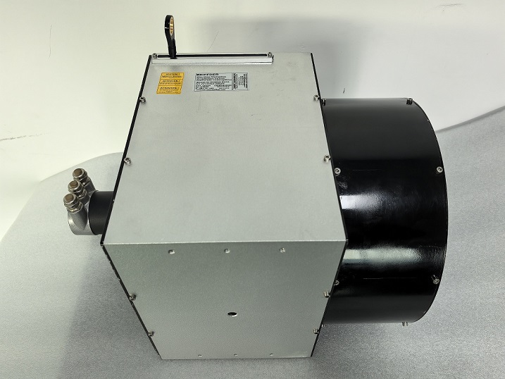
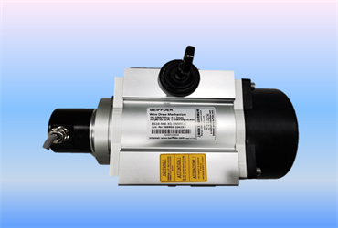
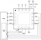
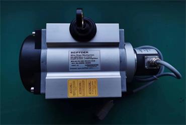
图片中显示了需要使用中心按钮的其他硬件连接。我使用Fritzing绘制了图表,但它没有代表最可能的引脚布局的旋转编码器组件,因此只需将该图表与注释结合使用,然后查看旋转编码器的照片,即可了解更多内容。可能正在寻找旋转编码器引脚布局方面的信息。
旋转编码器一侧(与具有三个引脚的一侧相对)的两个引脚之一需要接地,而另一端则要连接到Arduino的数字引脚。我已将D4用于示例草图。如果您选择其他引脚,请不要忘记更改草图中的 buttonPin 的值。
接下来是步骤2中的代码。
步骤2:代码
这是代码。通过查看结构和评论,我希望您会发现很容易适应您的特定需求!
/*******Interrupt-based Rotary Encoder Menu Sketch*******
* by Simon Merrett, based on insight from Oleg Mazurov, Nick Gammon, rt and Steve Spence, and code from Nick Gammon
* 3,638 bytes with debugging on UNO, 1,604 bytes without debugging
*/
// Rotary encoder declarations
static int pinA = 2; // Our first hardware interrupt pin is digital pin 2
static int pinB = 3; // Our second hardware interrupt pin is digital pin 3
volatile byte aFlag = 0; // let‘s us know when we’re expecting a rising edge on pinA to signal that the encoder has arrived at a detent
volatile byte bFlag = 0; // let‘s us know when we’re expecting a rising edge on pinB to signal that the encoder has arrived at a detent (opposite direction to when aFlag is set)
volatile byte encoderPos = 0; //this variable stores our current value of encoder position. Change to int or uin16_t instead of byte if you want to record a larger range than 0-255
volatile byte oldEncPos = 0; //stores the last encoder position value so we can compare to the current reading and see if it has changed (so we know when to print to the serial monitor)
volatile byte reading = 0; //somewhere to store the direct values we read from our interrupt pins before checking to see if we have moved a whole detent
// Button reading, including debounce without delay function declarations
const byte buttonPin = 4; // this is the Arduino pin we are connecting the push button to
byte oldButtonState = HIGH; // assume switch open because of pull-up resistor
const unsigned long debounceTime = 10; // milliseconds
unsigned long buttonPressTime; // when the switch last changed state
boolean buttonPressed = 0; // a flag variable
// Menu and submenu/setting declarations
byte Mode = 0; // This is which menu mode we are in at any given time (top level or one of the submenus)
const byte modeMax = 3; // This is the number of submenus/settings you want
byte setting1 = 0; // a variable which holds the value we set
byte setting2 = 0; // a variable which holds the value we set
byte setting3 = 0; // a variable which holds the value we set
/* Note: you may wish to change settingN etc to int, float or boolean to suit your application.
Remember to change “void setAdmin(byte name,*BYTE* setting)” to match and probably add some
“modeMax”-type overflow code in the “if(Mode == N && buttonPressed)” section*/
void setup() {
//Rotary encoder section of setup
pinMode(pinA, INPUT_PULLUP); // set pinA as an input, pulled HIGH to the logic voltage (5V or 3.3V for most cases)
pinMode(pinB, INPUT_PULLUP); // set pinB as an input, pulled HIGH to the logic voltage (5V or 3.3V for most cases)
attachInterrupt(0,PinA,RISING); // set an interrupt on PinA, looking for a rising edge signal and executing the “PinA” Interrupt Service Routine (below)
attachInterrupt(1,PinB,RISING); // set an interrupt on PinB, looking for a rising edge signal and executing the “PinB” Interrupt Service Routine (below)
// button section of setup
pinMode (buttonPin, INPUT_PULLUP); // setup the button pin
// DEBUGGING section of setup
Serial.begin(9600); // DEBUGGING: opens serial port, sets data rate to 9600 bps
}
void loop() {
rotaryMenu();
// carry out other loop code here
}
void rotaryMenu() { //This handles the bulk of the menu functions without needing to install/include/compile a menu library
//DEBUGGING: Rotary encoder update display if turned
if(oldEncPos != encoderPos) { // DEBUGGING
Serial.println(encoderPos);// DEBUGGING. Sometimes the serial monitor may show a value just outside modeMax due to this function. The menu shouldn‘t be affected.
oldEncPos = encoderPos;// DEBUGGING
}// DEBUGGING
// Button reading with non-delay() debounce - thank you Nick Gammon!
byte buttonState = digitalRead (buttonPin);
if (buttonState != oldButtonState){
if (millis () - buttonPressTime 》= debounceTime){ // debounce
buttonPressTime = millis (); // when we closed the switch
oldButtonState = buttonState; // remember for next time
if (buttonState == LOW){
Serial.println (“Button closed”); // DEBUGGING: print that button has been closed
buttonPressed = 1;
}
else {
Serial.println (“Button opened”); // DEBUGGING: print that button has been opened
buttonPressed = 0;
}
} // end if debounce time up
} // end of state change
//Main menu section
if (Mode == 0) {
if (encoderPos 》 (modeMax+10)) encoderPos = modeMax; // check we haven’t gone out of bounds below 0 and correct if we have
else if (encoderPos 》 modeMax) encoderPos = 0; // check we haven‘t gone out of bounds above modeMax and correct if we have
if (buttonPressed){
Mode = encoderPos; // set the Mode to the current value of input if button has been pressed
Serial.print(“Mode selected: ”); //DEBUGGING: print which mode has been selected
Serial.println(Mode); //DEBUGGING: print which mode has been selected
buttonPressed = 0; // reset the button status so one press results in one action
if (Mode == 1) {
Serial.println(“Mode 1”); //DEBUGGING: print which mode has been selected
encoderPos = setting1; // start adjusting Vout from last set point
}
if (Mode == 2) {
Serial.println(“Mode 2”); //DEBUGGING: print which mode has been selected
encoderPos = setting2; // start adjusting Imax from last set point
}
if (Mode == 3) {
Serial.println(“Mode 3”); //DEBUGGING: print which mode has been selected
encoderPos = setting3; // start adjusting Vmin from last set point
}
}
}
if (Mode == 1 && buttonPressed) {
setting1 = encoderPos; // record whatever value your encoder has been turned to, to setting 3
setAdmin(1,setting1);
//code to do other things with setting1 here, perhaps update display
}
if (Mode == 2 && buttonPressed) {
setting2 = encoderPos; // record whatever value your encoder has been turned to, to setting 2
setAdmin(2,setting2);
//code to do other things with setting2 here, perhaps update display
}
if (Mode == 3 && buttonPressed){
setting3 = encoderPos; // record whatever value your encoder has been turned to, to setting 3
setAdmin(3,setting3);
//code to do other things with setting3 here, perhaps update display
}
}
// Carry out common activities each time a setting is changed
void setAdmin(byte name, byte setting){
Serial.print(“Setting ”); //DEBUGGING
Serial.print(name); //DEBUGGING
Serial.print(“ = ”); //DEBUGGING
Serial.println(setting);//DEBUGGING
encoderPos = 0; // reorientate the menu index - optional as we have overflow check code elsewhere
buttonPressed = 0; // reset the button status so one press results in one action
Mode = 0; // go back to top level of menu, now that we’ve set values
Serial.println(“Main Menu”); //DEBUGGING
}
//Rotary encoder interrupt service routine for one encoder pin
void PinA(){
cli(); //stop interrupts happening before we read pin values
reading = PIND & 0xC; // read all eight pin values then strip away all but pinA and pinB‘s values
if(reading == B00001100 && aFlag) { //check that we have both pins at detent (HIGH) and that we are expecting detent on this pin’s rising edge
encoderPos --; //decrement the encoder‘s position count
bFlag = 0; //reset flags for the next turn
aFlag = 0; //reset flags for the next turn
}
else if (reading == B00000100) bFlag = 1; //signal that we’re expecting pinB to signal the transition to detent from free rotation
sei(); //restart interrupts
}
//Rotary encoder interrupt service routine for the other encoder pin
void PinB(){
cli(); //stop interrupts happening before we read pin values
reading = PIND & 0xC; //read all eight pin values then strip away all but pinA and pinB‘s values
if (reading == B00001100 && bFlag) { //check that we have both pins at detent (HIGH) and that we are expecting detent on this pin’s rising edge
encoderPos ++; //increment the encoder‘s position count
bFlag = 0; //reset flags for the next turn
aFlag = 0; //reset flags for the next turn
}
else if (reading == B00001000) aFlag = 1; //signal that we’re expecting pinA to signal the transition to detent from free rotation
sei(); //restart interrupts
}
// end of sketch!
在任何对菜单执行操作都不重要的行的每个注释的开头,我都使用了“ DEBUGGING”。如果您对菜单功能满意,则可能需要注释掉或删除这些行以缩小编译的草图尺寸。
请注意,菜单导航的关键部分是在用户滚动浏览选项和设置时反馈给用户。因此,如果您选择不包括DEBUGGING行,则可能应该使用另一个可视指示器(例如LCD文本显示器,LED),编码器输入正在导航菜单并更改设置。
如果我注释掉DEBUGGING行(注意,菜单导航仍需要一些视觉反馈),Arduino Uno的编译后代码约为1,650字节,希望在ATMEGA328P上留出足够的空间以容纳草图中更令人兴奋的部分!
转到步骤3,了解菜单系统的工作原理。
步骤3:操作和结论
操作
如果上传此草图后在Arduino中打开串行监视器,并开始转动编码器轴,则应该看到顶层菜单在子菜单/选项数中旋转您拥有(使用 modeMax 变量进行限制)。如果按中间的按钮,您会看到已选择要滚动到的模式/子菜单,现在可以自由选择要滚动浏览该子菜单中的0-255值。现在,如果您按下中央按钮,则将其设置为 setting1 或 setting2 或 setting3 等。Arduino自动并立即返回
上电后,Arduino会记住您将每个设置设置为什么,并且如果您返回子菜单以获取设置,则您已经设置了一个值到此为止,它将从您选择的最后一个值开始进行编码器调整!
结论
我着手编写一些基于草图的代码,旋转编码器导航Arduino的基本菜单。我还尝试使其具有可读性,以便与某些替代方案不同,有人可以看到菜单结构,并知道他们需要进行哪些更改才能根据自己的需要定制菜单。
此代码是基本的和通用的,专门用于演示功能,同时易于适应您自己的应用程序。它使用串行监视器作为基本的调试工具,如果您想查看代码的工作原理,也不需要单独显示。希望您发现它有用,并受到启发进行编辑,修改和改进!
责任编辑:wv
-
编码器
+关注
关注
45文章
4023浏览量
143739 -
Arduino
+关注
关注
191文章
6535浏览量
197664
发布评论请先 登录

绝对式旋转编码器常用什么类型磁铁?

磁铁在编码器中的作用与应用

增量型旋转编码器:工业自动化的“精密之眼”
探索AEDR - 9930E:三通道反射式增量旋转编码器的技术剖析
旋转编码器增量:工业自动化领域的“精密之眼”
Vishay RAIK060 旋转绝对感应套件编码器技术解析
增量式编码器工作原理是什么?

国产编码器在人形机器人领域的进展
多圈增量式编码器:工业自动化中的“旋转记忆大师”
圣邦微电子推出高度集成旋转磁编码器芯片VCE2755
新品|Unit Step16,16 定位BCD旋转编码器控制单元

增量型旋转编码器:工业智能化的“精密罗盘”
增量型编码器与绝对值型编码器怎么选择?
Bourns 扩展增量式编码器产品线,旋转寿命功能再升级


评论