 怎样制作Arduino OBD2扫描仪

步骤1:准备ELM327板以绕过USB桥接芯片
ELM327电缆外壳上的标签,用细小的星形螺钉拧下4个螺钉
然后拿出木板。
提示: 借用Girlfrien/妻子的表情,并在连接到OBD2连接器的连接器的一侧做一个标记,以这种方式将其取出时会知道它会走到哪一边,因为它可以双向移动,因此在此可指示的情况下,无需移除上述连接器。
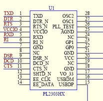
将2线连接到板上的TX和RX引脚,在随附的照片中,我包括了USB Bridge芯片的引脚排列信息。请小心,尽管我设法取消焊接了一些我无法放回的组件,但幸运的是,此后它仍然可以工作。
提示:对arduino进行编程,以便对其进行编程写入串行监视器时,它们之间有一些短的延迟,然后将跳线电缆连接到arduino的TX引脚上,并与电路板的另一端相碰,以查看在哪里可以进行一些串行活动,表面安装的LED闪烁为发生通信,不幸的是,这在RX端不起作用,但是在图片中很容易看到我将其焊接到板上的位置。
注意: USB电缆通过4针连接器连接到板上,我将中间的2条切掉,以便ELM327在连接时无法与PC通信,这样,它仅从PC的USB端口和板上的串行控制器获取电源将不会被允许Arduino与之交谈的PC占用
一旦将其放回盒子中,我就将其录音因为在我的吉普车中,箱子挡住了我的路,无法在驾驶员座位上驾驶它,所以我将把外壳用于其他用途。
步骤2:将Arduino LCD Shield连接到Arduino
将Arduino LCD Shield连接到arduino,然后将其连接到要编程的PC。
下面是我的Arduino Sketch,我注意到格式混乱有了一些代码,我可以获得一些与此版本有关的信息,您也可以在此处查看代码。
http://techtinker.co.za/viewtopic.php?f=14&t=17
// include the library code:
#include
//Declare Serial Read variables
int CmdCount=1;
byte inData;
char inChar;
String BuildINString=“”;
String DisplayString=“”;
long DisplayValue;
String SentMessage=“”;
int ByteCount=0;
long A;
int B;
int WorkingVal;
String WorkingString=“”; //Declare Buttons
int MenuID=0; // initialize the library with the numbers of the interface pins
LiquidCrystal lcd(8, 9, 4, 5, 6, 7); void setup()
{
// set up the LCD‘s number of columns and rows:
lcd.begin(16, 2);
// Print a message to the LCD.
lcd.setCursor(0, 0);
Bootup();//Simulate Bootup process doesnt have to be here this only makes it look cool
Retry:
lcd.setCursor(0, 0);
lcd.print(“Connecting.。..。. ”);
lcd.setCursor(0, 1);
lcd.print(“ ”);
Serial.begin(38400);
delay(500);
//Send a test message to see if the ELM327 Chip is responding
SentMessage = “ATI”;
Serial.println(“ATI”);delay(500);ReadData();
if (BuildINString.substring(1,7)==“ELM327”)
{
lcd.setCursor(0, 0);
lcd.print(“Welcome.。. ”);
lcd.setCursor(0, 1);
lcd.print(“Connection OK ”);
delay(1500);
}
else
{
lcd.setCursor(0, 0);
lcd.print(“Error ”);
lcd.setCursor(0, 1);
lcd.print(“No Connection! ”);
delay(1500);
goto Retry;
}
delay(1500);
} void loop() {
int x;
x = analogRead (0);
//Serial.println(x);
lcd.setCursor(10,1);
if (x 》 800 and x 《 820){lcd.print (“Select ”);}
if (x 》 620 and x 《 630){if (MenuID》0){MenuID--;}delay(250);}//Left
if (x 》 400 and x 《 415){lcd.print (“Down ”);}
if (x 》 190 and x 《 215){lcd.print (“Up ”);}
if (x 》 -10 and x 《 10){if (MenuID《11){MenuID++;}delay(250);} //Right if (MenuID==0){lcd.setCursor(0, 0);lcd.print(“01 Coolant Temp ”);lcd.setCursor(0, 1);lcd.print(DisplayString);SentMessage = “01 05”;Serial.println(“01 05”);delay(300);ReadData();}
if (MenuID==1){lcd.setCursor(0, 0);lcd.print(“02 IAT Temp ”);lcd.setCursor(0, 1);lcd.print(DisplayString);SentMessage = “01 0F”;Serial.println(“01 0F”);delay(300);ReadData();}
if (MenuID==2){lcd.setCursor(0, 0);lcd.print(“03 Ambient Temp ”);lcd.setCursor(0, 1);lcd.print(DisplayString);SentMessage = “01 46”;Serial.println(“01 46”);delay(300);ReadData();}
if (MenuID==3){lcd.setCursor(0, 0);lcd.print(“04 Throttle % ”);lcd.setCursor(0, 1);lcd.print(DisplayString);SentMessage = “01 11”;Serial.println(“01 11”);delay(300);ReadData();}
if (MenuID==4){lcd.setCursor(0, 0);lcd.print(“05 CAT 1 Temp ”);lcd.setCursor(0, 1);lcd.print(“Not Implemented ”);}
if (MenuID==5){lcd.setCursor(0, 0);lcd.print(“06 CAT 2 Temp ”);lcd.setCursor(0, 1);lcd.print(“Not Implemented ”);}
if (MenuID==6){lcd.setCursor(0, 0);lcd.print(“07 CAT 3 Temp ”);lcd.setCursor(0, 1);lcd.print(“Not Implemented ”);}
if (MenuID==7){lcd.setCursor(0, 0);lcd.print(“08 CAT 4 Temp ”);lcd.setCursor(0, 1);lcd.print(“Not Implemented ”);}
if (MenuID==8){lcd.setCursor(0, 0);lcd.print(“09 RPM ”);lcd.setCursor(0, 1);lcd.print(DisplayString);SentMessage = “01 0C”;Serial.println(“01 0C”);delay(300);ReadData();}
if (MenuID==9){lcd.setCursor(0, 0);lcd.print(“10 Vehicle Speed ”);lcd.setCursor(0, 1);lcd.print(DisplayString);SentMessage = “01 0D”;Serial.println(“01 0D”);delay(300);ReadData();}
if (MenuID==10){lcd.setCursor(0, 0);lcd.print(“11 Air Flow Rate ”);lcd.setCursor(0, 1);lcd.print(DisplayString);SentMessage = “01 10”;Serial.println(“01 10”);delay(300);ReadData();}
if (MenuID==11){lcd.setCursor(0, 0);lcd.print(“12 Barometric ”);lcd.setCursor(0, 1);lcd.print(DisplayString);SentMessage = “01 33”;Serial.println(“01 33”);delay(300);ReadData();}
步骤3:挂钩直到您的车辆
对Arduino进行编程后,请确保将Arduino的TX/RX引脚连接到ELM327板上的TX/RX引脚。
该代码通过发送命令“ ATI”来确保其能够与ELM327芯片通信,如果i t并非液晶显示屏上将显示“错误,无连接”,如果它可以正常工作的话,它将在液晶显示屏上显示欢迎消息。
从那里,您只需按左右按钮即可在
冷却液温度,IAT温度,环境温度,油门%,RPM,车辆速度,空气流速,大气压力
您可以添加如果愿意,可以根据需要将更多菜单更改为
有关更多PID的信息,请参见Wikihttp://en.wikipedia.org/wiki/OBD-II_PIDs。
您可以使用再次插入窗口的手机支架来固定它,并使用USB手机充电器为Arduino供电,ELM327将通过引脚16上的OBD端口供电,引脚16为正,引脚4/5为负。
责任编辑:wv
-
扫描仪
+关注
关注
2文章
459浏览量
68934 -
Arduino
+关注
关注
190文章
6527浏览量
197452
发布评论请先 登录

EMI扫描仪定位触控板电路板干扰源测试案例

禾赛科技与如视即将推出手持实景扫描仪庞加莱R1
SICK激光扫描仪:为工业高精度检测及测量保驾护航
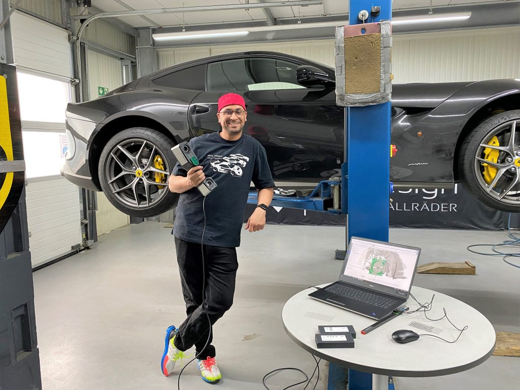
200万粉汽车达人的改装秘诀:用这台手持扫描仪,让法拉利轮辋完美适配

Brother全新发布两款网络扫描仪,助力企业加速迈入数字化办公新生态

M12连接器在激光扫描仪传感器上的广泛运用
蔡司三维扫描仪第三方代抄数检测机构

超酷的树莓派激光雷达扫描仪!


评论