 怎样用Arduino将手势传感器和LED环组合

步骤1:组件
1。 Arduino UNO
2。 usb cable
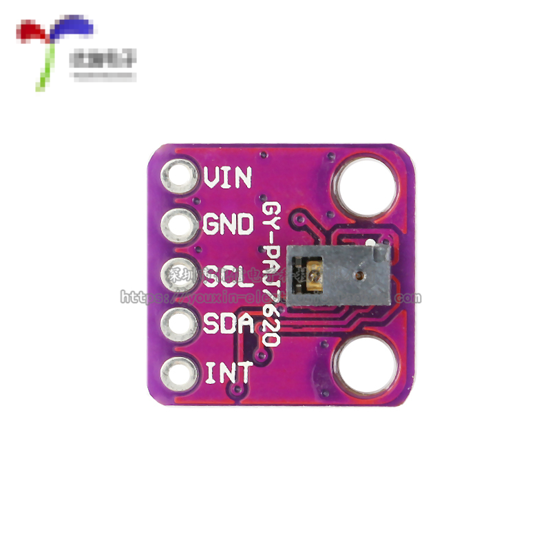
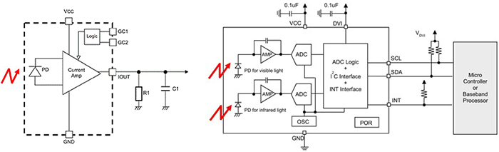
3. APDS9960手势传感器
4。 24 led neopixel led ring
5. 雄性 - 男性,男性 - 男性面包板电缆
6。 面包板
7. LED环的5 V电源(我正在使用4节电池)
8 。 要将新像素环连接到面包板,您需要将三个公引脚焊接到它:GND,PWR和控制引脚。为此你需要一个烙铁和助焊剂
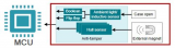
这里的主要部件是APDS-9960手势传感器和24个新像素环。您可以根据需要切换不同的arduinos,usb线缆电源和面包板。
步骤2:组装和上传
在开始之前,请确保您拥有所有组件。我们将有一些很好的步骤:)我还将Fritzing原理图作为图片和fritzing格式附加。
1。将3个公引脚焊接到新像素环(GND,PWR,控制引脚)
2。将新像素环连接到面包板上
3。将APDS9960传感器连接到面包板
4。接地:电池组,arduino UNO,APDS9960和neopixel到面包板地面
5。连接电源:arduino UNO 3V至APDS9960电源引脚,neopixel至电池组电源
6。将neopixel控制引脚连接到arduino D6引脚
7。将APDS9960的SDA和SCL分别连接到A4和A5
8。将APDS9960中断引脚连接到arduino D2
代码上传
首先,您需要下载并安装必要的arduino库:
1。 Neopixel ring library
2。手势传感器库
如果您不知道如何安装arduino库,请查看本教程。
在下一节中,我将把代码直接嵌入到本教程中,所以如果你愿意,你可以从那里复制并粘贴它。
最后使用usb线将arduino连接到电脑,将1.5伏电池放入电池组,然后将草图上传到arduino。
第3步:它是如何工作的?
在最后一部分中,我们将学习如何将这些组件组合在一起,如何使用它们的库以及我如何使用它们构建我的代码:
首先让我们快速浏览一下传感器和我们将使用的neopixel库API方法
1 。来自adafruit的 Neopixel API
从这个库我们将使用控制单个led颜色的方法并应用它们
- 包括库:
#include
- 声明库
#define NEOPIXED_CONTROL_PIN 6
#define NUM_LEDS 24
Adafruit_NeoPixel strip = Adafruit_NeoPixel(NUM_LEDS, NEOPIXED_CONTROL_PIN, NEO_RBG + NEO_KHZ800);
- 初始化
#typically inside the setup block
void setup() {
strip.begin();
# maybe some other stuff here # 。..。
}
- 点亮单个像素然后应用所有修改条带(以某种方式呈现)
# set up pixel 0 to be red
strip.setPixelColor(0, strip.Color(255, 0, 0));
# set up pixel 1 to be green
strip.setPixelColor(1, strip.Color(0, 255, 0));
# set up pixel 2 to be blue
strip.setPixelColor(2, strip.Color(0, 0 255));
strip.show();
2。 APDS 9960手势传感器
从这个库我们将使用“读取手势”功能。此功能将能够区分左右,上下,近远命令。这里有一个技巧,我们不会连续询问传感器的最后一个手势。电路板能够通过已发现手势的中断“ping”。
- 包括库,类似于neopixel
- 将库声明为中断引脚,和中断标志
#define APDS9960_INT 2
SparkFun_APDS9960 apds = SparkFun_APDS9960();
int isr_flag = 0;
- 初始化库,通常在设置函数内
void setup()
{
# declare the interrupt pin as INPUT and attach a function to it
pinMode(APDS9960_INT, INPUT);
attachInterrupt(0, interruptRoutine, FALLING);
if ( apds.init() && apds.enableGestureSensor(true)) {
Serial.println(“APDS-9960 initialization complete”);
} else {
Serial.println(“Something went wrong during APDS-9960 init!”);
}
# initialize other things maybe
}
- 定义中断函数,这里我们只设置一个flag
void interruptRoutine() {
isr_flag = 1;
}
- 在循环函数内部定期检查标志以查看是否已检测到手势
void loop()
{
# check the flag
if( isr_flag == 1 ) {
# if the flag is set, remove the interrupt, make the necessary processing inside handleGesture() function
# and then reset the flag and reattach the interrupt
detachInterrupt(0);
handleGesture();
isr_flag = 0;
attachInterrupt(0, interruptRoutine, FALLING);
}
# some other code here maybe
}
- 定义handleGesture()函数我们在哪里可以要求最后一个手势
void handleGesture() {
# if no gesture is avalible return, this is only a safe check
if ( !apds.isGestureAvailable() ) {
return;
}
# reads the last gesture, compares with the known ones and print a message
switch ( apds.readGesture() ) {
case DIR_UP:
Serial.println(“UP”);
break;
case DIR_DOWN:
Serial.println(“DOWN”);
break;
case DIR_LEFT:
Serial.println(“LEFT”);
break;
case DIR_RIGHT:
Serial.println(“RIGHT”);
break;
case DIR_FAR:
Serial.println(“FAR”);
break;
}
}
现在让我们看看整个代码的运行情况:
所以我已经解释了手势传感器的基本API和新像素环现在让我们把事情放在一起:
算法运行如下:
- 初始化库(参见上面的代码)
- 创建一个led数组强度被称为“ledStates”。该阵列将包含24个LED强度,以150到2的递减方式排列
- 在主循环内部检查中断引脚是否已被修改,如果是,则需要更改LED的动画或颜色
- “handleGesture()”函数检查最后一个手势并为UP -DOWN手势调用函数“toggleColor”或为LEFT - RIGHT手势设置全局变量“ledDirection”
- “toggleColor()”函数只是改变一个名为“colorSelection”的全局变量,其中一个值为0,1,2
- 在主循环函数中也有另一个名为“animateLeds();”的函数。叫做。此函数检查是否超过100毫秒,如果是,则使用“rotateLeds()”函数旋转LED,然后重新绘制它们
- “rotateLeds()”将向前或向后“旋转”LED使用另一个名为“intermediateLedStates”的数组。
旋转“效果”将如下所示:
# after initialization
{150, 100, 70, 50, 40, 30, 10, 2, 0, 0, 0, 0, 0, 0, 0, 0, 0, 0, 0, 0, 0, 0, 0, 0};
# after rotateLeds() is called
{0, 150, 100, 70, 50, 40, 30, 10, 2, 0, 0, 0, 0, 0, 0, 0, 0, 0, 0, 0, 0, 0, 0, 0};
# after rotateLeds() is called again
{0, 0, 150, 100, 70, 50, 40, 30, 10, 2, 0, 0, 0, 0, 0, 0, 0, 0, 0, 0, 0, 0, 0, 0};
# and so on
首先创建新阵列并复制新位置上的旧led强度(增加位置)或减少它)。之后用“intermediateLedStates”覆盖“ledStates”数组,这样过程将在100毫秒后继续。
#include “SparkFun_APDS9960.h”
#include “Adafruit_NeoPixel.h”
#include “Wire.h”
#define NEOPIXED_CONTROL_PIN 6
#define NUM_LEDS 24
#define APDS9960_INT 2
#define LED_SPEED_STEP_INTERVAL 100
Adafruit_NeoPixel strip = Adafruit_NeoPixel(NUM_LEDS, NEOPIXED_CONTROL_PIN, NEO_RBG + NEO_KHZ800);
SparkFun_APDS9960 apds = SparkFun_APDS9960();
unsigned long lastLedChangeTime = 0;
short ledDirection = 0;
short colorSelection = 0;
byte ledStates[] = {150, 100, 70, 50, 40, 30, 10, 2, 0, 0, 0, 0,
0, 0, 0, 0, 0, 0, 0, 0, 0, 0, 0, 0};
int isr_flag = 0;
void setup()
{
Serial.begin(9600);
Serial.println(“Program started”);
strip.begin();
pinMode(APDS9960_INT, INPUT);
attachInterrupt(0, interruptRoutine, FALLING);
if ( apds.init() && apds.enableGestureSensor(true)) {
Serial.println(“APDS-9960 initialization complete”);
} else {
Serial.println(“Something went wrong during APDS-9960 init!”);
}
lastLedChangeTime = millis();
Serial.println(“Init succesfully”);
}
void loop()
{
if( isr_flag == 1 ) {
detachInterrupt(0);
handleGesture();
isr_flag = 0;
attachInterrupt(0, interruptRoutine, FALLING);
}
animateLeds();
}
void interruptRoutine()
{
isr_flag = 1;
}
/**
* This will handle gestures from the APDS9960 sensor
* Up and Down gestures will call toggleColor function
* Left and Right gestures will change the led animation
*/
void handleGesture() {
if ( !apds.isGestureAvailable() ) {
return;
}
switch ( apds.readGesture() ) {
case DIR_UP:
Serial.println(“UP”);
toggleColor();
break;
case DIR_DOWN:
Serial.println(“DOWN”);
toggleColor();
break;
case DIR_LEFT:
ledDirection = 1;
Serial.println(“LEFT”);
break;
case DIR_RIGHT:
ledDirection = -1;
Serial.println(“RIGHT”);
break;
case DIR_FAR:
ledDirection = 0;
Serial.println(“FAR”);
break;
}
}
/**
* Change current leds color
* Each time this function is called will change the leds state
*/
void toggleColor()
{
if (colorSelection == 0) {
colorSelection = 1;
} else if (colorSelection == 1) {
colorSelection = 2;
} else {
colorSelection = 0;
}
}
/**
* The animation will run after LED_SPEED_STEP_INTERVAL millis
* First the rotateLeds function is called, then the leds colors are set using the strip api
*/
void animateLeds()
{
if (millis() - lastLedChangeTime 《 LED_SPEED_STEP_INTERVAL) {
return;
}
rotateLeds();
for (int i=0; i 《 NUM_LEDS; i++) {
strip.setPixelColor(i, getColor(ledStates[i]));
strip.show();
}
lastLedChangeTime = millis();
}
/**
* Using a secondary array “intermediateLedStates”, leds intensities are animated
* First the values from “ledStates” are copied on “intermediateLedStates” like so
* let‘s sat the “ledStates” array is {100, 80, 60, 0, 0, 0} and the ledDirection is 1
* then after this function is called “ledStates” array is {0, 100, 80, 60, 0, 0} simulating a rotation effect
*/
void rotateLeds()
{
byte intermediateLedStates[NUM_LEDS];
for (int i=0; i 《 NUM_LEDS; i++) {
intermediateLedStates[i] = 0;
}
for (int i=0; i 《 NUM_LEDS; i++) {
if (ledDirection == 1) {
if (i == NUM_LEDS -1) {
intermediateLedStates[0] = ledStates[i];
} else {
intermediateLedStates[i + 1] = ledStates[i];
}
} else {
if (i == 0) {
intermediateLedStates[NUM_LEDS - 1] = ledStates[i];
} else {
intermediateLedStates[i - 1] = ledStates[i];
}
}
}
for (int i=0; i 《 NUM_LEDS; i++) {
ledStates[i] = intermediateLedStates[i];
}
}
uint32_t getColor(int intensity)
{
switch (colorSelection) {
case 0:
return strip.Color(intensity, 0, 0);
case 1:
return strip.Color(0, intensity, 0);
default:
return strip.Color(0, 0, intensity);
}
}
-
led
+关注
关注
244文章
24727浏览量
692524 -
Arduino
+关注
关注
190文章
6527浏览量
197467 -
手势传感器
+关注
关注
1文章
13浏览量
13048
发布评论请先 登录
化工园区环网箱局放传感器——应用实践

霍尔传感器磁铁用哪种材质好?磁力要很强吗?

探索OPT3001环境光传感器:高精度与灵活性的完美结合
霍尔传感器磁环的极数决定了脉冲信号的多少

STM32驱动PAJ7620手势识别传感器
探索Thermometrics压力与温度组合传感器:卓越性能与广泛应用


Texas Instruments IWRL6432工业用毫米波雷达传感器数据手册
基于锁相环的无轴承同步磁阻电机无速度传感器检测技术
如何为您的应用选择光传感器
德州仪器光传感器选择指南
用示波器测量传感器的放大电路及供电


评论