 如何将LSM303连接到Arduino

概述
LSM303分支板结合了磁力计/罗盘模块和三轴加速度计,构成了紧凑的导航子系统。 I2C接口与3.3v和5v处理器兼容,并且两个引脚可以由其他I2C设备共享。结合L3GD20等3轴陀螺仪,您将拥有完整的IMU(惯性测量单元)所需的所有传感器,以用于空中,陆地或海洋导航。
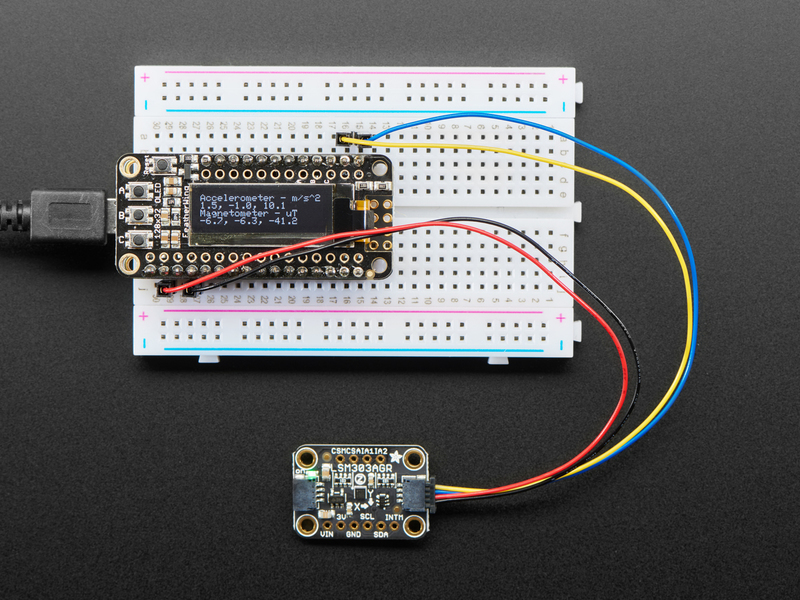
在本教程中,我们将向您展示如何将LSM303连接到Arduino,CircuitPython开发板或Blinka支持的设备,以及如何使用它来测量相对于地球磁场的方向以及在三个轴上的加速度。
新版LSM303AGR的一个重要功能是它包括一个 STEMMA QT 连接器,无需焊接即可使用。 只需将STEMMA QT插入公头连接线,即可将其连接到带有母头的面包板或开发板,重新参加比赛!您甚至可以使用STEMMA QT电缆将其与其他STEMMA QT分支连接起来
i》
工作原理:
传感器组成硅晶片上的微机械结构。有一些用于测量X,Y和Z轴上的加速度和磁场的结构
加速度测量
这些结构被多晶硅弹簧悬挂,当它们在X,Y和/或Z轴上受加速度作用时,它们可以偏转。挠曲会导致固定板和连接到悬挂结构的板之间的电容发生变化。每个轴上的电容变化都会转换为与该轴上的加速度成比例的输出电压。
磁场测量
这些结构与加速度计的结构相似,但是用微观线圈蚀刻。励磁电流流经线圈,由于磁场而产生的洛伦兹力使结构发生偏转。偏转再次转换为与该轴上的磁场强度成比例的输出电压。
我拥有哪个LSM303?
现在有两个由Adafruit制造的LSM303突破口! Schnikes!它们的功能几乎相同,但又有足够的差异,以至于它们需要磁力计的不同驱动器。为什么只有磁力计?好吧,我要告诉你一个小秘密:LSM303是两个传感器贴在同一个盒子里!
因为两个封装都具有相同的加速度传感器,且寄存器布局相同,所以我们可以使用两者都使用相同的加速度计驱动器。磁力计尽管都具有相同的I2C地址(0x1E),但寄存器布局却完全不同,这意味着它们各自需要自己的驱动程序库。
因此,您将需要知道你有哪个版本。这是区分两个 Adafruit 突破的一种高度科学的方法:
LSM303AGR是黑色的,说“ LSM303AGR”不同于
LSM303DLHC是蓝色并且说“ LSM303DLHC”
复杂,我知道,但我相信您。下面概述了更多细微的差异
LSM303AGR
adafruit块上的新孩子是LSM303AGR。这是对LSM303系列的更新,该系列体积更小,内部装有不同的磁力计芯片。我们的突破如下:
除了体积更小,更容易丢失筹码外,还有其他一些区别。芯片本身暴露了磁力计(INTM)的中断引脚(也许是内置的新型磁力计传感器的功能?)以及加速度计和磁力计的芯片选择引脚( CSA 和 CSM )。
两者之间的另一个令人兴奋的区别是增加了两个 STEMMA QT 连接器,每个连接器的一侧板。这样一来,您无需焊接即可使用该传感器,并且可以与其他STEMMA QT传感器链接。
请注意,虽然LSM303AGR分支具有CS引脚,但它仅支持3线SPI,而我们无法使用它。喜欢冒险的人可以参考数据表并尝试一下!欢迎PR;)
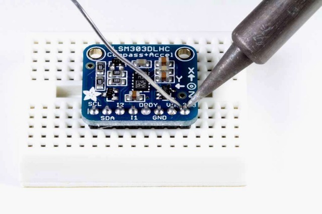
LSM303/LSM303DLHC
AdafruitLSM303分支使用LSM303 DLHC ,看起来像这样:
》
与LSM303AGR相比,您可以看到传感器本身(中间的黑色矩形)实际上更大。此外,引脚的顺序不同,并且LSM303DLH公开了 DRDY (数据就绪)引脚。
插脚

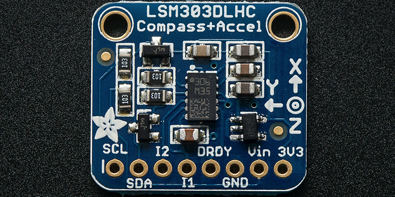
电源引脚
Vin -这是电源引脚。由于传感器芯片使用的是3.3 VDC,因此我们在板载了一个稳压器,该稳压器将采用3-5VDC的电压并将其安全地向下转换。要为电路板供电,请为其提供与微控制器逻辑电平相同的功率-例如,对于像Arduino这样的5V微控制器,请使用5V
3Vo -这是稳压器的3.3V输出,如果您愿意,可以从中获得100mA的电流。
GND -电源和逻辑的公共接地
I2C逻辑引脚
SCL -I2C时钟引脚,连接到微控制器的I2C时钟线。该引脚经过电平转换,因此您可以使用3-5V逻辑,并且该引脚上具有 10K上拉。
SDA -I2C数据引脚,连接到微控制器的I2C数据线。该引脚经过电平转换,因此您可以使用3-5V逻辑,并且该引脚上具有 10K上拉。
STEMMA QT- ,这些连接器允许您可以连接到具有 STEMMA QT 连接器的开发板或具有各种关联附件的其他东西的连接器
其他通用引脚
IA1 -加速度计的第一个中断引脚。仅限3V逻辑
IA2-加速度计的第二个中断引脚。仅3V逻辑
LSM303AGR仅限
INTM -磁力计的中断引脚。仅限3V逻辑
CSA-加速度计的CS引脚。仅限3V逻辑
CSM-磁力计的CS引脚。仅限3V逻辑
请注意,虽然LSM303AGR突破口具有CS引脚,仅支持我们无法使用的3线SPI。喜欢冒险的人可以参考数据表并尝试一下!欢迎PR;)
仅适用于LSM303DLH
DRDY -这是数据就绪引脚。仅限3V逻辑
程序集
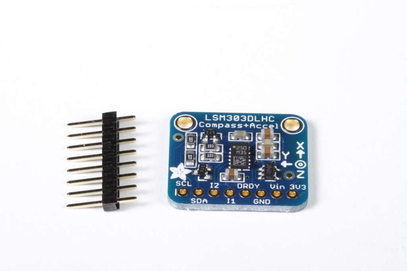
电路板组装:所有表面安装组件都已预先焊接到电路板上。您可以将连接直接焊接到板上,也可以安装标题栏(已提供)以简化在面包板上的使用。

放置页眉,如有必要,将页眉切成一定长度,然后将长针向下插入面包板。
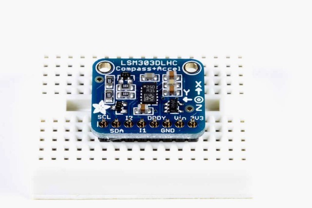
放置板子将板子放在排针顶部。支撑必要的背面,以便在焊接之前将电路板弄平。
然后焊接!焊接每个引脚以确保良好的电气连接。
如果您是焊接新手,请查阅我们的出色焊接指南。
Arduino
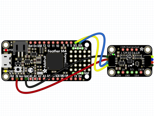
Arduino接线
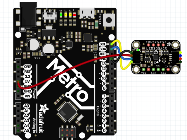
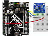
Connect 板载VCC(红线)5V Arduino板(Uno等),则将strong》改为 Arduino 5V 。如果您的板为 3V, 相反。
连接板子 GND(黑线)到 Arduino GND
将板 SCL(黄线)连接到 Arduino SCL
连接板 SDA(蓝线)到 Arduino SDA
ul》
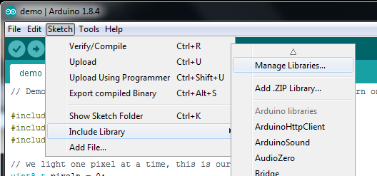
安装库
要开始使用LSM303,您需要安装加速度计库,并板的磁力计库。另外,您将需要Adafruit_Sensor库以及Adafruit_BusIO库,该库允许它以与其他类似传感器一致的方式返回数据。可以使用Arduino IDE中的库管理器安装所有库:
在继续之前,请确保您知道传感器的版本,
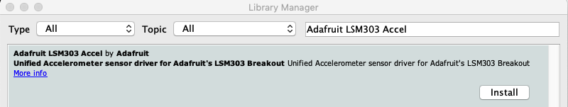
安装加速计库
点击管理库。.. 菜单项,搜索 Adafruit LSM303 Accel ,然后选择 Adafruit_LSM303_Accel 库:
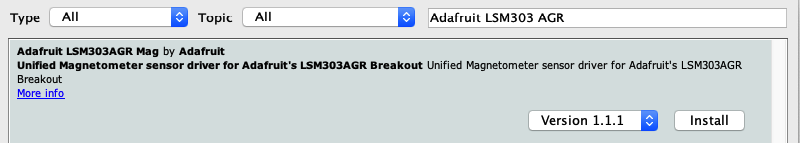
安装磁力计库
最后,您需要在LSM303中安装磁力计库。确保下载适用于您的分组讨论板的正确驱动程序。
LSM303AGR
在库管理器中搜索 Adafruit_LSM303AGR_Mag 库:
LSM303/LSM303DLHC
在库管理器中搜索 Adafruit_LSM303DLH_Mag 库:
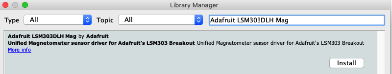
安装帮助程序库
对 Adafruit BusIO 库执行相同的过程:
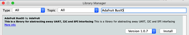
最后,对 Adafruit Unified Sensor 库:

加速度计演示
第一个演示将向您展示如何获得加速度计最有效的读数:测量加速度!
打开文件-》示例-》 Adafruit LSM303 Accel -》 accelsensor 并上传到与传感器连接的Arduino。
将草图上传到板上并打开Serial Monitor(工具-》 Serial Monitor )以 115200波特。您应该看到启动时打印的当前配置设置的值,然后是与X,Y和Z轴类似的加速度读数:
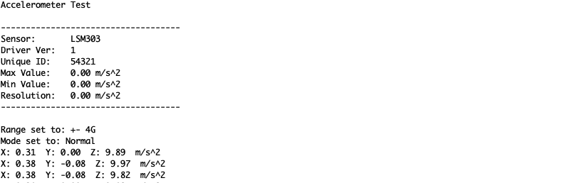
Adafruit_LSM303_Accel_Unified 传感器Adafruit_LSM303_Accel库中的类报告X,Y和Z轴加速度计的读数直接以米/秒为平方。库中的accelsensor示例代码从传感器读取并将加速度读数打印到串行监视器中。
在静止状态下,传感器不应报告任何加速度,除非是由于重力(大约9.8米/秒平方)。通过计算重力矢量相对于X,Y和Z轴的角度,该设备可以用作倾角仪。
基本磁力计读数
第一个演示将向您展示如何获得加速度计最有效的读数:测量加速度!
LSM303AGR
打开文件-》示例-》 Adafruit LSM303AGR Mag -》磁传感器并上传到您的Arduino接线端
LSM303/LSM303DLH
打开文件-》示例-》 Adafruit LSM303DLH Mag -》磁传感器,然后
将草图上传到您的电路板上,并以 115200波特打开串行监视器(工具-》串行监视器)。您应该看到启动时打印的当前配置设置的值,然后是X,Y和Z轴的磁场读数,类似于:
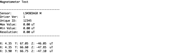
磁力仪库中的传感器类报告X,Y和Z轴磁力仪读数直接在微型Teslas中。 magsensor 示例代码从传感器读取并将微型特斯拉读数打印到串行监视器。
在没有任何强磁场的情况下,传感器读数应反映地球的磁场(介于20到60微特拉斯之间)。当传感器保持水平时,通过计算磁场相对于X和Y轴的角度,该设备可用作指南针。
计算指南针航向
要将microTesla读数转换为0-360度指南针航向,我们可以使用atan2()函数来计算由Y和X轴读数定义的向量的角度。结果将以弧度为单位,因此我们将其乘以180度并除以Pi以将其转换为度。
LSM303AGR
打开文件-》示例-》 Adafruit LSM303AGR Mag -》罗盘,并上传到与传感器连接的Arduino。
LSM303/LSM303DLH
打开文件-》示例-》 Adafruit LSM303DLH Mag -》罗盘,并通过传感器连接到Arduino。
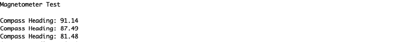
将草图上传到板上并打开串行监视器(工具-》串行监视器),位于 115200波特。您将看到航向计算打印到串行监视器。如果在传感器运行时旋转传感器,则会看到航向更改:
加速度计演示代码
下载:Project Zip 或 accelsensor.ino | 在Github上查看
复制代码
#include
#include
#include
/* Assign a unique ID to this sensor at the same time */
Adafruit_LSM303_Accel_Unified accel = Adafruit_LSM303_Accel_Unified(54321);
void displaySensorDetails(void) {
sensor_t sensor;
accel.getSensor(&sensor);
Serial.println(“------------------------------------”);
Serial.print(“Sensor: ”);
Serial.println(sensor.name);
Serial.print(“Driver Ver: ”);
Serial.println(sensor.version);
Serial.print(“Unique ID: ”);
Serial.println(sensor.sensor_id);
Serial.print(“Max Value: ”);
Serial.print(sensor.max_value);
Serial.println(“ m/s^2”);
Serial.print(“Min Value: ”);
Serial.print(sensor.min_value);
Serial.println(“ m/s^2”);
Serial.print(“Resolution: ”);
Serial.print(sensor.resolution);
Serial.println(“ m/s^2”);
Serial.println(“------------------------------------”);
Serial.println(“”);
delay(500);
}
void setup(void) {
#ifndef ESP8266
while (!Serial)
; // will pause Zero, Leonardo, etc until serial console opens
#endif
Serial.begin(9600);
Serial.println(“Accelerometer Test”);
Serial.println(“”);
/* Initialise the sensor */
if (!accel.begin()) {
/* There was a problem detecting the ADXL345 。.. check your connections */
Serial.println(“Ooops, no LSM303 detected 。.. Check your wiring!”);
while (1)
;
}
/* Display some basic information on this sensor */
displaySensorDetails();
accel.setRange(LSM303_RANGE_4G);
Serial.print(“Range set to: ”);
lsm303_accel_range_t new_range = accel.getRange();
switch (new_range) {
case LSM303_RANGE_2G:
Serial.println(“+- 2G”);
break;
case LSM303_RANGE_4G:
Serial.println(“+- 4G”);
break;
case LSM303_RANGE_8G:
Serial.println(“+- 8G”);
break;
case LSM303_RANGE_16G:
Serial.println(“+- 16G”);
break;
}
accel.setMode(LSM303_MODE_NORMAL);
Serial.print(“Mode set to: ”);
lsm303_accel_mode_t new_mode = accel.getMode();
switch (new_mode) {
case LSM303_MODE_NORMAL:
Serial.println(“Normal”);
break;
case LSM303_MODE_LOW_POWER:
Serial.println(“Low Power”);
break;
case LSM303_MODE_HIGH_RESOLUTION:
Serial.println(“High Resolution”);
break;
}
}
void loop(void) {
/* Get a new sensor event */
sensors_event_t event;
accel.getEvent(&event);
/* Display the results (acceleration is measured in m/s^2) */
Serial.print(“X: ”);
Serial.print(event.acceleration.x);
Serial.print(“ ”);
Serial.print(“Y: ”);
Serial.print(event.acceleration.y);
Serial.print(“ ”);
Serial.print(“Z: ”);
Serial.print(event.acceleration.z);
Serial.print(“ ”);
Serial.println(“m/s^2”);
/* Delay before the next sample */
delay(500);
}
#include
#include
#include
/* Assign a unique ID to this sensor at the same time */
Adafruit_LSM303_Accel_Unified accel = Adafruit_LSM303_Accel_Unified(54321);
void displaySensorDetails(void) {
sensor_t sensor;
accel.getSensor(&sensor);
Serial.println(“------------------------------------”);
Serial.print(“Sensor: ”);
Serial.println(sensor.name);
Serial.print(“Driver Ver: ”);
Serial.println(sensor.version);
Serial.print(“Unique ID: ”);
Serial.println(sensor.sensor_id);
Serial.print(“Max Value: ”);
Serial.print(sensor.max_value);
Serial.println(“ m/s^2”);
Serial.print(“Min Value: ”);
Serial.print(sensor.min_value);
Serial.println(“ m/s^2”);
Serial.print(“Resolution: ”);
Serial.print(sensor.resolution);
Serial.println(“ m/s^2”);
Serial.println(“------------------------------------”);
Serial.println(“”);
delay(500);
}
void setup(void) {
#ifndef ESP8266
while (!Serial)
; // will pause Zero, Leonardo, etc until serial console opens
#endif
Serial.begin(9600);
Serial.println(“Accelerometer Test”);
Serial.println(“”);
/* Initialise the sensor */
if (!accel.begin()) {
/* There was a problem detecting the ADXL345 。.. check your connections */
Serial.println(“Ooops, no LSM303 detected 。.. Check your wiring!”);
while (1)
;
}
/* Display some basic information on this sensor */
displaySensorDetails();
accel.setRange(LSM303_RANGE_4G);
Serial.print(“Range set to: ”);
lsm303_accel_range_t new_range = accel.getRange();
switch (new_range) {
case LSM303_RANGE_2G:
Serial.println(“+- 2G”);
break;
case LSM303_RANGE_4G:
Serial.println(“+- 4G”);
break;
case LSM303_RANGE_8G:
Serial.println(“+- 8G”);
break;
case LSM303_RANGE_16G:
Serial.println(“+- 16G”);
break;
}
accel.setMode(LSM303_MODE_NORMAL);
Serial.print(“Mode set to: ”);
lsm303_accel_mode_t new_mode = accel.getMode();
switch (new_mode) {
case LSM303_MODE_NORMAL:
Serial.println(“Normal”);
break;
case LSM303_MODE_LOW_POWER:
Serial.println(“Low Power”);
break;
case LSM303_MODE_HIGH_RESOLUTION:
Serial.println(“High Resolution”);
break;
}
}
void loop(void) {
/* Get a new sensor event */
sensors_event_t event;
accel.getEvent(&event);
/* Display the results (acceleration is measured in m/s^2) */
Serial.print(“X: ”);
Serial.print(event.acceleration.x);
Serial.print(“ ”);
Serial.print(“Y: ”);
Serial.print(event.acceleration.y);
Serial.print(“ ”);
Serial.print(“Z: ”);
Serial.print(event.acceleration.z);
Serial.print(“ ”);
Serial.println(“m/s^2”);
/* Delay before the next sample */
delay(500);
}
LSM303AGR磁力计和指南针代码
下载:Project Zip 或 magsensor.ino | 在Github上查看
复制代码
#include
#include
#include
/* Assign a unique ID to this sensor at the same time */
Adafruit_LSM303AGR_Mag_Unified mag = Adafruit_LSM303AGR_Mag_Unified(12345);
void displaySensorDetails(void) {
sensor_t sensor;
mag.getSensor(&sensor);
Serial.println(“------------------------------------”);
Serial.print(“Sensor: ”);
Serial.println(sensor.name);
Serial.print(“Driver Ver: ”);
Serial.println(sensor.version);
Serial.print(“Unique ID: ”);
Serial.println(sensor.sensor_id);
Serial.print(“Max Value: ”);
Serial.print(sensor.max_value);
Serial.println(“ uT”);
Serial.print(“Min Value: ”);
Serial.print(sensor.min_value);
Serial.println(“ uT”);
Serial.print(“Resolution: ”);
Serial.print(sensor.resolution);
Serial.println(“ uT”);
Serial.println(“------------------------------------”);
Serial.println(“”);
delay(500);
}
void setup(void) {
#ifndef ESP8266
while (!Serial)
; // will pause Zero, Leonardo, etc until serial console opens
#endif
Serial.begin(115200);
Serial.println(“Magnetometer Test”);
Serial.println(“”);
/* Enable auto-gain */
mag.enableAutoRange(true);
/* Initialise the sensor */
if (!mag.begin()) {
/* There was a problem detecting the LSM303 。.. check your connections */
Serial.println(“Ooops, no LSM303AGR detected 。.. Check your wiring!”);
while (1)
;
}
/* Display some basic information on this sensor */
displaySensorDetails();
}
void loop(void) {
/* Get a new sensor event */
sensors_event_t event;
mag.getEvent(&event);
/* Display the results (magnetic vector values are in micro-Tesla (uT)) */
Serial.print(“X: ”);
Serial.print(event.magnetic.x);
Serial.print(“ ”);
Serial.print(“Y: ”);
Serial.print(event.magnetic.y);
Serial.print(“ ”);
Serial.print(“Z: ”);
Serial.print(event.magnetic.z);
Serial.print(“ ”);
Serial.println(“uT”);
/* Note: You can also get the raw (non unified values) for */
/* the last data sample as follows. The .getEvent call populates */
/* the raw values used below. */
// Serial.print(“X Raw: ”); Serial.print(mag.raw.x); Serial.print(“ ”);
// Serial.print(“Y Raw: ”); Serial.print(mag.raw.y); Serial.print(“ ”);
// Serial.print(“Z Raw: ”); Serial.print(mag.raw.z); Serial.println(“”);
/* Delay before the next sample */
delay(500);
}
#include
#include
#include
/* Assign a unique ID to this sensor at the same time */
Adafruit_LSM303AGR_Mag_Unified mag = Adafruit_LSM303AGR_Mag_Unified(12345);
void displaySensorDetails(void) {
sensor_t sensor;
mag.getSensor(&sensor);
Serial.println(“------------------------------------”);
Serial.print(“Sensor: ”);
Serial.println(sensor.name);
Serial.print(“Driver Ver: ”);
Serial.println(sensor.version);
Serial.print(“Unique ID: ”);
Serial.println(sensor.sensor_id);
Serial.print(“Max Value: ”);
Serial.print(sensor.max_value);
Serial.println(“ uT”);
Serial.print(“Min Value: ”);
Serial.print(sensor.min_value);
Serial.println(“ uT”);
Serial.print(“Resolution: ”);
Serial.print(sensor.resolution);
Serial.println(“ uT”);
Serial.println(“------------------------------------”);
Serial.println(“”);
delay(500);
}
void setup(void) {
#ifndef ESP8266
while (!Serial)
; // will pause Zero, Leonardo, etc until serial console opens
#endif
Serial.begin(115200);
Serial.println(“Magnetometer Test”);
Serial.println(“”);
/* Enable auto-gain */
mag.enableAutoRange(true);
/* Initialise the sensor */
if (!mag.begin()) {
/* There was a problem detecting the LSM303 。.. check your connections */
Serial.println(“Ooops, no LSM303AGR detected 。.. Check your wiring!”);
while (1)
;
}
/* Display some basic information on this sensor */
displaySensorDetails();
}
void loop(void) {
/* Get a new sensor event */
sensors_event_t event;
mag.getEvent(&event);
/* Display the results (magnetic vector values are in micro-Tesla (uT)) */
Serial.print(“X: ”);
Serial.print(event.magnetic.x);
Serial.print(“ ”);
Serial.print(“Y: ”);
Serial.print(event.magnetic.y);
Serial.print(“ ”);
Serial.print(“Z: ”);
Serial.print(event.magnetic.z);
Serial.print(“ ”);
Serial.println(“uT”);
/* Note: You can also get the raw (non unified values) for */
/* the last data sample as follows. The .getEvent call populates */
/* the raw values used below. */
// Serial.print(“X Raw: ”); Serial.print(mag.raw.x); Serial.print(“ ”);
// Serial.print(“Y Raw: ”); Serial.print(mag.raw.y); Serial.print(“ ”);
// Serial.print(“Z Raw: ”); Serial.print(mag.raw.z); Serial.println(“”);
/* Delay before the next sample */
delay(500);
}
下载:Project Zip 或 compass.ino | 在Github上查看
复制代码
#include
#include
#include
Adafruit_LSM303AGR_Mag_Unified mag = Adafruit_LSM303AGR_Mag_Unified(12345);
void setup(void)
{
Serial.begin(115200);
Serial.println(“Magnetometer Test”); Serial.println(“”);
/* Initialise the sensor */
if(!mag.begin())
{
/* There was a problem detecting the LSM303 。.. check your connections */
Serial.println(“Ooops, no LSM303 detected 。.. Check your wiring!”);
while(1);
}
}
void loop(void)
{
/* Get a new sensor event */
sensors_event_t event;
mag.getEvent(&event);
float Pi = 3.14159;
// Calculate the angle of the vector y,x
float heading = (atan2(event.magnetic.y,event.magnetic.x) * 180) / Pi;
// Normalize to 0-360
if (heading 《 0)
{
heading = 360 + heading;
}
Serial.print(“Compass Heading: ”);
Serial.println(heading);
delay(500);
}
#include
#include
#include
Adafruit_LSM303AGR_Mag_Unified mag = Adafruit_LSM303AGR_Mag_Unified(12345);
void setup(void)
{
Serial.begin(115200);
Serial.println(“Magnetometer Test”); Serial.println(“”);
/* Initialise the sensor */
if(!mag.begin())
{
/* There was a problem detecting the LSM303 。.. check your connections */
Serial.println(“Ooops, no LSM303 detected 。.. Check your wiring!”);
while(1);
}
}
void loop(void)
{
/* Get a new sensor event */
sensors_event_t event;
mag.getEvent(&event);
float Pi = 3.14159;
// Calculate the angle of the vector y,x
float heading = (atan2(event.magnetic.y,event.magnetic.x) * 180) / Pi;
// Normalize to 0-360
if (heading 《 0)
{
heading = 360 + heading;
}
Serial.print(“Compass Heading: ”);
Serial.println(heading);
delay(500);
}
LSM303/LSM303DLH磁力计和指南针代码
下载:Project Zip 或 magsensor.ino | 在Github上查看
复制代码
#include
#include
#include
/* Assign a unique ID to this sensor at the same time */
Adafruit_LSM303DLH_Mag_Unified mag = Adafruit_LSM303DLH_Mag_Unified(12345);
void displaySensorDetails(void) {
sensor_t sensor;
mag.getSensor(&sensor);
Serial.println(“------------------------------------”);
Serial.print(“Sensor: ”);
Serial.println(sensor.name);
Serial.print(“Driver Ver: ”);
Serial.println(sensor.version);
Serial.print(“Unique ID: ”);
Serial.println(sensor.sensor_id);
Serial.print(“Max Value: ”);
Serial.print(sensor.max_value);
Serial.println(“ uT”);
Serial.print(“Min Value: ”);
Serial.print(sensor.min_value);
Serial.println(“ uT”);
Serial.print(“Resolution: ”);
Serial.print(sensor.resolution);
Serial.println(“ uT”);
Serial.println(“------------------------------------”);
Serial.println(“”);
delay(500);
}
void setup(void) {
#ifndef ESP8266
while (!Serial)
; // will pause Zero, Leonardo, etc until serial console opens
#endif
Serial.begin(115200);
Serial.println(“Magnetometer Test”);
Serial.println(“”);
/* Enable auto-gain */
mag.enableAutoRange(true);
/* Initialise the sensor */
if (!mag.begin()) {
/* There was a problem detecting the LSM303 。.. check your connections */
Serial.println(“Ooops, no LSM303 detected 。.. Check your wiring!”);
while (1)
;
}
/* Display some basic information on this sensor */
displaySensorDetails();
}
void loop(void) {
/* Get a new sensor event */
sensors_event_t event;
mag.getEvent(&event);
/* Display the results (magnetic vector values are in micro-Tesla (uT)) */
Serial.print(“X: ”);
Serial.print(event.magnetic.x);
Serial.print(“ ”);
Serial.print(“Y: ”);
Serial.print(event.magnetic.y);
Serial.print(“ ”);
Serial.print(“Z: ”);
Serial.print(event.magnetic.z);
Serial.print(“ ”);
Serial.println(“uT”);
/* Delay before the next sample */
delay(500);
} #include
#include
#include
/* Assign a unique ID to this sensor at the same time */
Adafruit_LSM303DLH_Mag_Unified mag = Adafruit_LSM303DLH_Mag_Unified(12345);
void displaySensorDetails(void) {
sensor_t sensor;
mag.getSensor(&sensor);
Serial.println(“------------------------------------”);
Serial.print(“Sensor: ”);
Serial.println(sensor.name);
Serial.print(“Driver Ver: ”);
Serial.println(sensor.version);
Serial.print(“Unique ID: ”);
Serial.println(sensor.sensor_id);
Serial.print(“Max Value: ”);
Serial.print(sensor.max_value);
Serial.println(“ uT”);
Serial.print(“Min Value: ”);
Serial.print(sensor.min_value);
Serial.println(“ uT”);
Serial.print(“Resolution: ”);
Serial.print(sensor.resolution);
Serial.println(“ uT”);
Serial.println(“------------------------------------”);
Serial.println(“”);
delay(500);
}
void setup(void) {
#ifndef ESP8266
while (!Serial)
; // will pause Zero, Leonardo, etc until serial console opens
#endif
Serial.begin(115200);
Serial.println(“Magnetometer Test”);
Serial.println(“”);
/* Enable auto-gain */
mag.enableAutoRange(true);
/* Initialise the sensor */
if (!mag.begin()) {
/* There was a problem detecting the LSM303 。.. check your connections */
Serial.println(“Ooops, no LSM303 detected 。.. Check your wiring!”);
while (1)
;
}
/* Display some basic information on this sensor */
displaySensorDetails();
}
void loop(void) {
/* Get a new sensor event */
sensors_event_t event;
mag.getEvent(&event);
/* Display the results (magnetic vector values are in micro-Tesla (uT)) */
Serial.print(“X: ”);
Serial.print(event.magnetic.x);
Serial.print(“ ”);
Serial.print(“Y: ”);
Serial.print(event.magnetic.y);
Serial.print(“ ”);
Serial.print(“Z: ”);
Serial.print(event.magnetic.z);
Serial.print(“ ”);
Serial.println(“uT”);
/* Delay before the next sample */
delay(500);
}
下载:Project Zip 或 compass.ino | 在Github上查看
复制代码
#include
#include
#include
Adafruit_LSM303DLH_Mag_Unified mag = Adafruit_LSM303DLH_Mag_Unified(12345);
void setup(void) {
Serial.begin(115200);
Serial.println(“Magnetometer Test”);
Serial.println(“”);
/* Initialise the sensor */
if (!mag.begin()) {
/* There was a problem detecting the LSM303 。.. check your connections */
Serial.println(“Ooops, no LSM303 detected 。.. Check your wiring!”);
while (1)
;
}
}
void loop(void) {
/* Get a new sensor event */
sensors_event_t event;
mag.getEvent(&event);
float Pi = 3.14159;
// Calculate the angle of the vector y,x
float heading = (atan2(event.magnetic.y, event.magnetic.x) * 180) / Pi;
// Normalize to 0-360
if (heading 《 0) {
heading = 360 + heading;
}
Serial.print(“Compass Heading: ”);
Serial.println(heading);
delay(500);
} #include
#include
#include
Adafruit_LSM303DLH_Mag_Unified mag = Adafruit_LSM303DLH_Mag_Unified(12345);
void setup(void) {
Serial.begin(115200);
Serial.println(“Magnetometer Test”);
Serial.println(“”);
/* Initialise the sensor */
if (!mag.begin()) {
/* There was a problem detecting the LSM303 。.. check your connections */
Serial.println(“Ooops, no LSM303 detected 。.. Check your wiring!”);
while (1)
;
}
}
void loop(void) {
/* Get a new sensor event */
sensors_event_t event;
mag.getEvent(&event);
float Pi = 3.14159;
// Calculate the angle of the vector y,x
float heading = (atan2(event.magnetic.y, event.magnetic.x) * 180) / Pi;
// Normalize to 0-360
if (heading 《 0) {
heading = 360 + heading;
}
Serial.print(“Compass Heading: ”);
Serial.println(heading);
delay(500);
}
Adafruit_LSM303DLHC库已存档
较早的LSM303DLH分支的Adafruit_LSM303DLHC库已归档,并已由上面使用的Adafruit_LSM303_Accel和Adafruit_LSM303DLH_Mag库替换。我们建议您切换到较新的库,因为不支持旧的库或添加了功能。
如果您仍然希望使用旧的库,则可以单击下面的按钮转到存储库或以ZIP格式下载。
存档的Adafruit_LSMDLHC存储库
下载Adafruit_LSM303DLHC
Python和CircuitPython
很容易将LSM303传感器与CircuitPython和Adafruit CircuitPython LSM303加速度计以及Adafruit CircuitPython LSM303DLH磁力计库一起使用。这些库可让您轻松编写可从传感器读取加速度和磁力计值的Python代码。
由于Adafruit_Blinka,您可以将此传感器与任何CircuitPython微控制器板或具有GPIO和Python的计算机一起使用,我们的CircuitPython-for-Python兼容性库。
在继续之前,请确保您知道传感器的版本
CircuitPython微控制器布线
首先连接LSM303使用I2C连接完全按照Arduino的前几页中的说明连接到板上。以下是使用I2C将Feather M0连接到传感器的示例:
 li》
li》
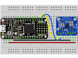
板3V 到传感器VIN(红线)
板GND 到传感器GND (黑线)
板SCL 到传感器SCL(黄线)
板SDA 到传感器SDA(蓝线)
Python计算机接线
因为有几十个 您可以使用的Linux计算机/主板,我们将显示Raspberry Pi的接线。对于其他平台,请访问Linux上的CircuitPython指南,以了解您的平台是否受支持。
以下是与I2C相连的Raspberry Pi:
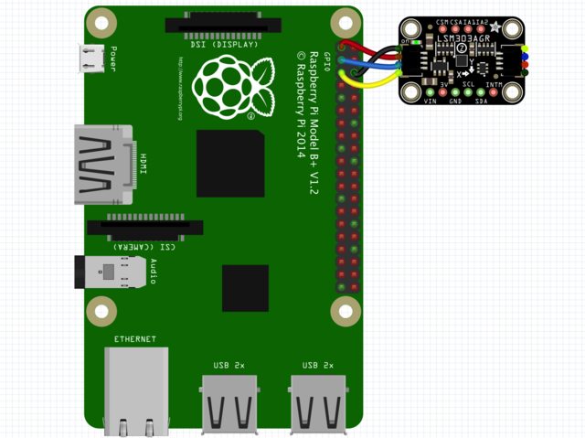


Pi 3V 到传感器VIN(红线)
Pi GND 到传感器GND(黑线)
Pi SCL 到传感器SCL(黄线)
Pi SDA 到传感器SDA(蓝线)
》
CircuitPython安装LSM303库
接下来,您需要安装Adafruit CircuitPython LSM303加速度计和Adafruit CircuitPython LSM303AGR或Adafruit CircuitPython LSM303DLH magn etometer(取决于您拥有的LSM303)库。
首先请确保您正在为板运行最新版本的Adafruit CircuitPython。
下一步,您需要安装使用硬件所需的库-请仔细按照以下步骤从Adafruit的CircuitPython库捆绑包中查找和安装这些库。我们的简介指南上有一个很棒的页面,介绍如何为快速和非表达板安装库包。
请记住非表达板,例如,您需要从束中手动安装必要的库:
adafruit_lsm303agr_mag.mpy或adafruit_lsm303dlh_mag.mpy
adafruit_lsm303_accel.mpy
adafruit_bus_device
adafruit_register
在继续之前,请确保您董事会的lib文件夹或根文件系统具有 adafruit_lsm303agr_mag .mpy或adafruit_lsm303dlh_mag.mpy, adafruit_lsm303_accel.mpy,adafruit_register,和 adafruit_bus_device 文件和文件夹
下一步连接到开发板的串行REPL,因此您位于CircuitPython的》》》 提示符下。
LSM303 Li的Python安装braries
您需要安装 Adafruit_Blinka 库,该库在Python中提供了CircuitPython支持。这可能还需要在您的平台上启用I2C并验证您正在运行Python3。由于每个平台都有所不同,并且Linux经常更改,请访问Linux上的CircuitPython指南以准备好您的计算机!
完成后,从命令行运行以下命令:
sudo pip3 install adafruit-circuitpython-lsm303-accel
然后为您的LSM303版本安装磁力计库。 :
LSM303AGR:
sudo pip3 install adafruit-circuitpython-lsm303agr-mag
LSM303DLH:
sudo pip3 install adafruit-circuitpython-lsm303dlh-mag
如果您的默认Python是版本3,则可能需要运行“ pip”。只要确保您不尝试在Python 2.x上使用CircuitPython,就不支持它!
CircuitPython和Python用法
这些示例使用adafruit_lsm303agr_mag库。如果您拥有lsm303dlh,则必须更改代码以使用adafruit_lsm303dlh_mag库
为演示传感器的用法,我们将对其进行初始化并读取
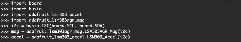
运行以下代码以导入必要的模块,并初始化与传感器的I2C连接:
》 LSM303AGR
下载:文件
复制代码
import board
import busio
import adafruit_lsm303_accel
import adafruit_lsm303agr_mag
i2c = busio.I2C(board.SCL, board.SDA)
mag = adafruit_lsm303agr_mag.LSM303AGR_Mag(i2c)
accel = adafruit_lsm303_accel.LSM303_Accel(i2c) import board
import busio
import adafruit_lsm303_accel
import adafruit_lsm303agr_mag
i2c = busio.I2C(board.SCL, board.SDA)
mag = adafruit_lsm303agr_mag.LSM303AGR_Mag(i2c)
accel = adafruit_lsm303_accel.LSM303_Accel(i2c)
LSM303DLH
下载:文件
复制代码
import board
import busio
import adafruit_lsm303_accel
import adafruit_lsm303dlh_mag
i2c = busio.I2C(board.SCL, board.SDA)
mag = adafruit_lsm303dlh_mag.LSM303DLH_Mag(i2c)
accel = adafruit_lsm303_accel.LSM303_Accel(i2c) import board
import busio
import adafruit_lsm303_accel
import adafruit_lsm303dlh_mag
i2c = busio.I2C(board.SCL, board.SDA)
mag = adafruit_lsm303dlh_mag.LSM303DLH_Mag(i2c)
accel = adafruit_lsm303_accel.LSM303_Accel(i2c)

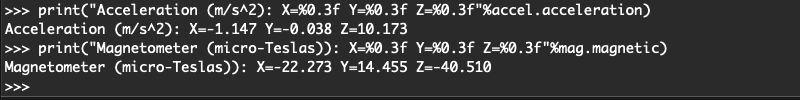
现在,您可以使用以下属性之一从传感器读取值:
加速度计
加速度-X,Y, Z加速度值,单位为米每秒每秒(m/s ^ 2)。
磁力计
磁性-微型特斯拉中X,Y,Z磁力计读数的三元组。
下载:文件
复制代码
print(“Acceleration (m/s^2): X=%0.3f Y=%0.3f Z=%0.3f”%accel.acceleration)
print(“Magnetometer (micro-Teslas)): X=%0.3f Y=%0.3f Z=%0.3f”%mag.magnetic) print(“Acceleration (m/s^2): X=%0.3f Y=%0.3f Z=%0.3f”%accel.acceleration)
print(“Magnetometer (micro-Teslas)): X=%0.3f Y=%0.3f Z=%0.3f”%mag.magnetic)
点击检测
LSM303的加速度计还可以检测单次或两次点击!
set_tap 方法可用于设置要检测的抽头数(1或2),以及设置抽头阈值。阈值越低,加速度计对检测抽头越敏感。您可能必须使用这个数字来找到适合您需求的值
在这里,我们还将使用 range 属性将加速度计的测量范围更改为 +/- 8G
下载:文件
复制代码
accel.range = adafruit_lsm303_accel.Range.RANGE_8G
accel.set_tap(1, 30)
while True:
if accel.tapped:
print(“Tapped! ”) accel.range = adafruit_lsm303_accel.Range.RANGE_8G
accel.set_tap(1, 30)
while True:
if accel.tapped:
print(“Tapped! ”)
当您在REPL中键入上面的代码并给传感器一个良好的固定点击时,您应该会看到类似于输出如下。如果看不到“已点击!” 消息,则可能需要调整阈值。
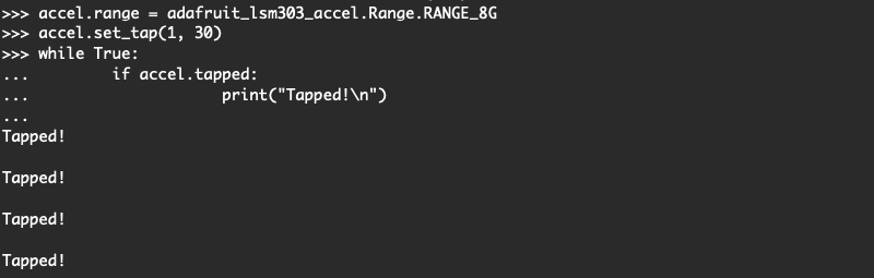
As您可以从上面看到,tapped属性将在一个单击事件的多个周期内返回True。您必须在代码中对此进行说明。不幸的是,这似乎只是传感器的一个怪癖
这是将LSM303与CircuitPython一起使用的全部内容。
下面是一个每秒读取传感器并打印其值的完整示例。将其另存为板上的 code.py 并打开REPL以查看输出。
点击检测代码
下载:Project Zip 或 tap_detection.py | 在Github上查看
复制代码
import board
import busio
import adafruit_lsm303_accel
i2c = busio.I2C(board.SCL, board.SDA)
accel = adafruit_lsm303_accel.LSM303_Accel(i2c)
accel.range = adafruit_lsm303_accel.Range.RANGE_8G
accel.set_tap(1, 30)
while True:
if accel.tapped:
print(“Tapped! ”)
import board
import busio
import adafruit_lsm303_accel
i2c = busio.I2C(board.SCL, board.SDA)
accel = adafruit_lsm303_accel.LSM303_Accel(i2c)
accel.range = adafruit_lsm303_accel.Range.RANGE_8G
accel.set_tap(1, 30)
while True:
if accel.tapped:
print(“Tapped! ”)
LSM303AGR示例代码
下载:Project Zip 或 lsm303agr_combined .py | 在Github上查看
复制代码
from time import sleep
import board
import busio
import adafruit_lsm303_accel
import adafruit_lsm303agr_mag
i2c = busio.I2C(board.SCL, board.SDA)
mag = adafruit_lsm303agr_mag.LSM303AGR_Mag(i2c)
accel = adafruit_lsm303_accel.LSM303_Accel(i2c)
while True:
print(“Acceleration (m/s^2): X=%0.3f Y=%0.3f Z=%0.3f”%accel.acceleration)
print(“Magnetometer (micro-Teslas)): X=%0.3f Y=%0.3f Z=%0.3f”%mag.magnetic)
print(“”)
sleep(0.5)
LSM303DLH示例代码
下载:Project Zip 或 lsm303dlh_combined.py | 在Github上查看
复制代码
from time import sleep
import board
import busio
import adafruit_lsm303_accel
import adafruit_lsm303dlh_mag
i2c = busio.I2C(board.SCL, board.SDA)
mag = adafruit_lsm303dlh_mag.LSM303DLH_Mag(i2c)
accel = adafruit_lsm303_accel.LSM303_Accel(i2c)
while True:
print(“Acceleration (m/s^2): X=%0.3f Y=%0.3f Z=%0.3f”%accel.acceleration)
print(“Magnetometer (micro-Teslas)): X=%0.3f Y=%0.3f Z=%0.3f”%mag.magnetic)
print(“”)
sleep(0.5)
Adafruit_CircuitPython_LSM303库已存档
用于较早的LSM303DLH突破的Adafruit_CircuitPython_LSM303库已存档,并已由上面使用的Adafruit_CircuitPython_LSM303_Accel和Adafruit_CircuitPython_LSM303DLH_Mag库替换。我们建议您切换到较新的库,因为不支持旧的库或添加了功能。
如果您仍然希望使用旧的库,则可以单击下面的按钮转到存储库或以ZIP格式下载。
已存档的Adafruit_CircuitPython_LSM303存储库
下载Adafruit_CircuitPython_LSM303
校准
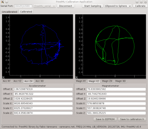
(Fabio Varesano的校准GUI图像)
LSM303芯片在出厂时已校准到足以满足多种目的的精确度。但是对于IMU等超临界应用程序,您可能需要进一步校准设备。
最终校准:
要进行超高精度加速度计校准,您将需要查看已故的Fabio Varesano提供的FreeIMU磁力计和加速度计GUI。上面的图像(来自Fabio网站)显示了传感器读数的图形表示以及根据原始数据计算出的校准偏差。
此全面的校准套件旨在在PC上运行。它太大了,无法在像Arduino这样的微控制器上运行,但是它产生的校准偏差可以并入您的Arduino草图中,以提高准确性。
简化的校准:
可以在Arduino上完成仍然产生良好结果的更简单方法。该方法使用一个简单的草图记录所有3轴上的最小和最大读数。运行草图时,在所有三个轴上缓慢旋转LSM303模块多次。目的是记录每个轴的绝对最小值和最大值,因此旋转得越多,捕获绝对峰值的可能性就越大。
请确保将传感器缓慢绕其中心旋转,以使加速度计读数将仅表示由于重力引起的加速度,而不表示由于运动引起的传感器线性加速度。稍后,草图输出将稳定。显示的值将是每个轴的最小和最大范围,可用于重新缩放传感器的输出。
通过校准草图获得的值可用于执行在三个轴上分别进行两点校准:两点校准
校准草图:
LSM303AGR
下载:Project Zip 或 calibration.ino | 在Github上查看
复制代码
#include
#include
#include
Adafruit_LSM303AGR_Mag_Unified mag = Adafruit_LSM303AGR_Mag_Unified(12345);
float MagMinX, MagMaxX;
float MagMinY, MagMaxY;
float MagMinZ, MagMaxZ;
long lastDisplayTime;
void setup(void)
{
Serial.begin(115200);
Serial.println(“LSM303 Calibration”); Serial.println(“”);
/* Initialise the magnetometer */
if(!mag.begin())
{
/* There was a problem detecting the LSM303 。.. check your connections */
Serial.println(“Ooops, no LSM303 detected 。.. Check your wiring!”);
while(1);
}
lastDisplayTime = millis();
}
void loop(void)
{
/* Get a new sensor event */
sensors_event_t magEvent;
mag.getEvent(&magEvent);
if (magEvent.magnetic.x 《 MagMinX) MagMinX = magEvent.magnetic.x;
if (magEvent.magnetic.x 》 MagMaxX) MagMaxX = magEvent.magnetic.x;
if (magEvent.magnetic.y 《 MagMinY) MagMinY = magEvent.magnetic.y;
if (magEvent.magnetic.y 》 MagMaxY) MagMaxY = magEvent.magnetic.y;
if (magEvent.magnetic.z 《 MagMinZ) MagMinZ = magEvent.magnetic.z;
if (magEvent.magnetic.z 》 MagMaxZ) MagMaxZ = magEvent.magnetic.z;
if ((millis() - lastDisplayTime) 》 1000) // display once/second
{
Serial.print(“Mag Minimums: ”); Serial.print(MagMinX); Serial.print(“ ”);Serial.print(MagMinY); Serial.print(“ ”); Serial.print(MagMinZ); Serial.println();
Serial.print(“Mag Maximums: ”); Serial.print(MagMaxX); Serial.print(“ ”);Serial.print(MagMaxY); Serial.print(“ ”); Serial.print(MagMaxZ); Serial.println(); Serial.println();
lastDisplayTime = millis();
}
}
#include
#include
#include
Adafruit_LSM303AGR_Mag_Unified mag = Adafruit_LSM303AGR_Mag_Unified(12345);
float MagMinX, MagMaxX;
float MagMinY, MagMaxY;
float MagMinZ, MagMaxZ;
long lastDisplayTime;
void setup(void)
{
Serial.begin(115200);
Serial.println(“LSM303 Calibration”); Serial.println(“”);
/* Initialise the magnetometer */
if(!mag.begin())
{
/* There was a problem detecting the LSM303 。.. check your connections */
Serial.println(“Ooops, no LSM303 detected 。.. Check your wiring!”);
while(1);
}
lastDisplayTime = millis();
}
void loop(void)
{
/* Get a new sensor event */
sensors_event_t magEvent;
mag.getEvent(&magEvent);
if (magEvent.magnetic.x 《 MagMinX) MagMinX = magEvent.magnetic.x;
if (magEvent.magnetic.x 》 MagMaxX) MagMaxX = magEvent.magnetic.x;
if (magEvent.magnetic.y 《 MagMinY) MagMinY = magEvent.magnetic.y;
if (magEvent.magnetic.y 》 MagMaxY) MagMaxY = magEvent.magnetic.y;
if (magEvent.magnetic.z 《 MagMinZ) MagMinZ = magEvent.magnetic.z;
if (magEvent.magnetic.z 》 MagMaxZ) MagMaxZ = magEvent.magnetic.z;
if ((millis() - lastDisplayTime) 》 1000) // display once/second
{
Serial.print(“Mag Minimums: ”); Serial.print(MagMinX); Serial.print(“ ”);Serial.print(MagMinY); Serial.print(“ ”); Serial.print(MagMinZ); Serial.println();
Serial.print(“Mag Maximums: ”); Serial.print(MagMaxX); Serial.print(“ ”);Serial.print(MagMaxY); Serial.print(“ ”); Serial.print(MagMaxZ); Serial.println(); Serial.println();
lastDisplayTime = millis();
}
}
LSM303/LSM303DLH
下载:项目Zip 或 calibration.ino | 在Github上查看
复制代码
#include
#include
//#include
#include
Adafruit_LSM303DLH_Mag_Unified mag = Adafruit_LSM303DLH_Mag_Unified(12345);
float MagMinX, MagMaxX;
float MagMinY, MagMaxY;
float MagMinZ, MagMaxZ;
long lastDisplayTime;
void setup(void) {
Serial.begin(115200);
Serial.println(“LSM303 Calibration”);
Serial.println(“”);
/* Initialise the magnetometer */
if (!mag.begin()) {
/* There was a problem detecting the LSM303 。.. check your connections */
Serial.println(“Ooops, no LSM303 detected 。.. Check your wiring!”);
while (1)
;
}
lastDisplayTime = millis();
}
void loop(void) {
/* Get a new sensor event */
sensors_event_t magEvent;
mag.getEvent(&magEvent);
if (magEvent.magnetic.x 《 MagMinX)
MagMinX = magEvent.magnetic.x;
if (magEvent.magnetic.x 》 MagMaxX)
MagMaxX = magEvent.magnetic.x;
if (magEvent.magnetic.y 《 MagMinY)
MagMinY = magEvent.magnetic.y;
if (magEvent.magnetic.y 》 MagMaxY)
MagMaxY = magEvent.magnetic.y;
if (magEvent.magnetic.z 《 MagMinZ)
MagMinZ = magEvent.magnetic.z;
if (magEvent.magnetic.z 》 MagMaxZ)
MagMaxZ = magEvent.magnetic.z;
if ((millis() - lastDisplayTime) 》 1000) // display once/second
{
Serial.print(“Mag Minimums: ”);
Serial.print(MagMinX);
Serial.print(“ ”);
Serial.print(MagMinY);
Serial.print(“ ”);
Serial.print(MagMinZ);
Serial.println();
Serial.print(“Mag Maximums: ”);
Serial.print(MagMaxX);
Serial.print(“ ”);
Serial.print(MagMaxY);
Serial.print(“ ”);
Serial.print(MagMaxZ);
Serial.println();
Serial.println();
lastDisplayTime = millis();
}
} #include
#include
//#include
#include
Adafruit_LSM303DLH_Mag_Unified mag = Adafruit_LSM303DLH_Mag_Unified(12345);
float MagMinX, MagMaxX;
float MagMinY, MagMaxY;
float MagMinZ, MagMaxZ;
long lastDisplayTime;
void setup(void) {
Serial.begin(115200);
Serial.println(“LSM303 Calibration”);
Serial.println(“”);
/* Initialise the magnetometer */
if (!mag.begin()) {
/* There was a problem detecting the LSM303 。.. check your connections */
Serial.println(“Ooops, no LSM303 detected 。.. Check your wiring!”);
while (1)
;
}
lastDisplayTime = millis();
}
void loop(void) {
/* Get a new sensor event */
sensors_event_t magEvent;
mag.getEvent(&magEvent);
if (magEvent.magnetic.x 《 MagMinX)
MagMinX = magEvent.magnetic.x;
if (magEvent.magnetic.x 》 MagMaxX)
MagMaxX = magEvent.magnetic.x;
if (magEvent.magnetic.y 《 MagMinY)
MagMinY = magEvent.magnetic.y;
if (magEvent.magnetic.y 》 MagMaxY)
MagMaxY = magEvent.magnetic.y;
if (magEvent.magnetic.z 《 MagMinZ)
MagMinZ = magEvent.magnetic.z;
if (magEvent.magnetic.z 》 MagMaxZ)
MagMaxZ = magEvent.magnetic.z;
if ((millis() - lastDisplayTime) 》 1000) // display once/second
{
Serial.print(“Mag Minimums: ”);
Serial.print(MagMinX);
Serial.print(“ ”);
Serial.print(MagMinY);
Serial.print(“ ”);
Serial.print(MagMinZ);
Serial.println();
Serial.print(“Mag Maximums: ”);
Serial.print(MagMaxX);
Serial.print(“ ”);
Serial.print(MagMaxY);
Serial.print(“ ”);
Serial.print(MagMaxZ);
Serial.println();
Serial.println();
lastDisplayTime = millis();
}
}
制作曲目!
现在让我们使用LSM303模块进行一些简单的导航!
此页面上的图像显示较旧的LSM303DLH。您也可以使用更新的LSM303AGR,但需要参考“引脚分配”页面来确定要使用的引脚
一天,制作曲目
在Prax草原上,
来一个北向Zax
和一个南向Zax。
此Zax-O-Meter是北部或南部Zax的理想导航工具。该项目演示了如何使用LSM303磁力计输出来实现简单的导航系统。无论您以哪种方式旋转,指针都将始终旋转到所需的行进方向。
永不退缩!这是我的规则。
从不退缩!
向西不远一英寸!
向东不一英寸!
Zax-O-Meter使用计算出的指南针航向作为连续旋转的反馈伺服。当指南针航向为零度(正北)时,伺服器停止旋转。与该值的任何偏差都会导致伺服器朝相反的方向旋转以进行补偿。负反馈的基本原理可用于构建自主机器人的导航系统。
材料:要构建Zax-O-Meter,您将需要:
Adafruit LSM303接线板
Arduino Uno
Arduino机箱
连续旋转伺服系统
跳线
卡片纸
纸板或泡沫芯
校准伺服器:为使Zax-O-Meter准确运行,您首先需要找到连续旋转伺服器的“中性”点。这是导致最小旋转的伺服输出值。该值通常约为90,但在伺服之间有所不同。运行此草图并修改值,直到获得最小旋转。那就是您应该在Zax-O-Meter草图中为ServoNeutral使用的值。
下载:文件
复制代码
#include
Servo servo;
void setup()
{
servo.attach(9); // attaches the servo on pin 9 to the servo object
servo.write(90); // change this value to achieve minimum rotation!
}
void loop()
{
} #include
Servo servo;
void setup()
{
servo.attach(9); // attaches the servo on pin 9 to the servo object
servo.write(90); // change this value to achieve minimum rotation!
}
void loop()
{
}
安装伺服器,标记并加宽外壳中的开口以适合伺服器。将伺服器的转子对准外壳的中心。向下按直到法兰与表面齐平,舵机应卡入到位并牢固固定。
安装Uno并将其连接使用随附的螺钉将Uno安装在机箱中。如下连接伺服和传感器:
伺服:
黑色-》 Gnd
红色-》 5v
白色-》数字引脚9
LSM303:
Gnd-》 Gnd
Vin-》 3.3v
SDA-》模拟4
SCL-》模拟5
然后将传感器导线穿过伺服器旁边的开口并关闭外壳。
添加指针从一些坚硬的硬纸板或泡沫芯,并用一些双面泡沫胶带将其粘贴到伺服喇叭上。
用一些双面泡沫胶带将传感器固定在箭头的下方。将传感器放置在尽可能远离伺服主体的位置,以避免电动机产生电磁干扰。
添加Zaxen!查找您最喜欢的Zax的图片。使用“画图”或其他图像编辑工具制作一对镜像图像。
将图像打印在一些较重的卡片纸上,然后将其折叠以制作双面图像。
将其切出并安装在其顶部。带有双面胶带的指示箭头。
代码:加载以下代码。不要忘记在“伺服校准”步骤中将“ ServoNeutral”更改为中性值。
示例代码适用于北向Zax,目标标题为0。如果您是南向说服的Zax ,targetHeading为180将使您一直处在向南的位置。对于那些背叛的人,请在0-360度之间选择任何targetHeading设置,然后开始在您选择的标题中进行跟踪!
下载:文件
复制代码
// **********************************************
// Zax-O-Meter Sketch
// for the Adafruit LSM303 Magnetometer Breakout
//
// Written by Bill Earl for Adafruit Industries
//
// **********************************************
#include
#include
#include
#include
/* Assign a unique ID to this sensor at the same time */
Adafruit_LSM303_Mag_Unified mag = Adafruit_LSM303_Mag_Unified(12345);
// This is our continuous rotation servo
Servo servo;
// Pi for calculations - not the raspberry type
const float Pi = 3.14159;
// This is the value that gives you minimal rotation on
// a continuous rotation servo. It is usually about 90.
// adjust this value to give minimal rotation for your servo
const float ServoNeutral = 97;
// This is the desired direction of travel
// expressed as a 0-360 degree compass heading
// 0.0 = North
// 90.0 = East
// 180.0 = South
// 270 = West
const float targetHeading = 0.0;
void setup(void)
{
Serial.begin(9600);
Serial.println(“Magnetometer Test”); Serial.println(“”);
/* Initialise the sensor */
if(!mag.begin())
{
/* There was a problem detecting the LSM303 。.. check your connections */
Serial.println(“Ooops, no LSM303 detected 。.. Check your wiring!”);
while(1);
}
servo.attach(9); // Attach servo to pin 9
}
void loop(void)
{
/* Get a new sensor event */
sensors_event_t event;
mag.getEvent(&event);
// Calculate the angle of the vector y,x
float heading = (atan2(event.magnetic.y,event.magnetic.x) * 180) / Pi;
// Normalize to 0-360
if (heading 《 0)
{
heading = 360 + heading;
}
// Calculate the error between tha measured heading and the target heading.
float error = heading - targetHeading;
if (error 》 180)
{
error = error - 360; // for angles 》 180, correct in the opposite direction.
}
// A non-zero difference between the heading and the
// targetHeading will bias the servoNeutral value and
// cause the servo to rotate back toward the targetHeading.
// The divisor is to reduce the reaction speed and avoid oscillations
servo.write(ServoNeutral + error / 4 );
delay(40);
} // **********************************************
// Zax-O-Meter Sketch
// for the Adafruit LSM303 Magnetometer Breakout
//
// Written by Bill Earl for Adafruit Industries
//
// **********************************************
#include
#include
#include
#include
/* Assign a unique ID to this sensor at the same time */
Adafruit_LSM303_Mag_Unified mag = Adafruit_LSM303_Mag_Unified(12345);
// This is our continuous rotation servo
Servo servo;
// Pi for calculations - not the raspberry type
const float Pi = 3.14159;
// This is the value that gives you minimal rotation on
// a continuous rotation servo. It is usually about 90.
// adjust this value to give minimal rotation for your servo
const float ServoNeutral = 97;
// This is the desired direction of travel
// expressed as a 0-360 degree compass heading
// 0.0 = North
// 90.0 = East
// 180.0 = South
// 270 = West
const float targetHeading = 0.0;
void setup(void)
{
Serial.begin(9600);
Serial.println(“Magnetometer Test”); Serial.println(“”);
/* Initialise the sensor */
if(!mag.begin())
{
/* There was a problem detecting the LSM303 。.. check your connections */
Serial.println(“Ooops, no LSM303 detected 。.. Check your wiring!”);
while(1);
}
servo.attach(9); // Attach servo to pin 9
}
void loop(void)
{
/* Get a new sensor event */
sensors_event_t event;
mag.getEvent(&event);
// Calculate the angle of the vector y,x
float heading = (atan2(event.magnetic.y,event.magnetic.x) * 180) / Pi;
// Normalize to 0-360
if (heading 《 0)
{
heading = 360 + heading;
}
// Calculate the error between tha measured heading and the target heading.
float error = heading - targetHeading;
if (error 》 180)
{
error = error - 360; // for angles 》 180, correct in the opposite direction.
}
// A non-zero difference between the heading and the
// targetHeading will bias the servoNeutral value and
// cause the servo to rotate back toward the targetHeading.
// The divisor is to reduce the reaction speed and avoid oscillations
servo.write(ServoNeutral + error / 4 );
delay(40);
}
下载和链接
文件 strong》
LSM303AGR
LSM303AGR数据表
PCB文件(Eagle格式)
Adafruit Fritzing库中的装饰对象
LSM303DLHC
LSM303DLHC数据表
PCB文件(鹰格式)
Adafruit中的Fritzing对象Fritzing库
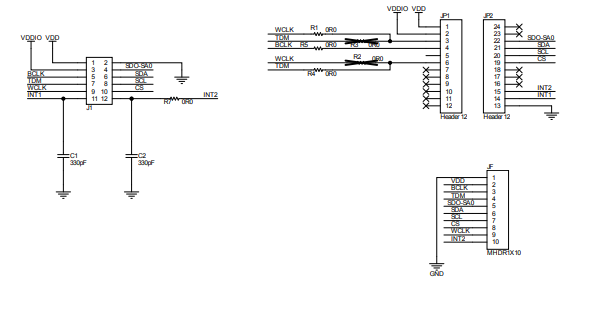
LSM0303AGR示意图&Fab Print


LSM303DLHC示意图和构造打印


责任编辑:wv
-
Arduino
+关注
关注
190文章
6515浏览量
195959 -
LSM303D
+关注
关注
0文章
2浏览量
9938
发布评论请先 登录
LSM6DSV16BX适配器套件技术解析与应用设计
M12连接器:卓越性能,铸就工业连接的坚固桥梁

M12连接器贵不贵

如何将项目从IAR迁移到Embedded Studio
请问如何将DLP lightcrafter连接成为普通的投影仪使用?
如何将ADS1278通过SPI与处理器连接?
使用插件将Excel连接到MySQL/MariaDB
EE-139:通过SPI端口将ADSP-2191与AD7476连接

EE-194:将AD1836A评估板连接到ADSP-21161N SHARC EZ-KIT Lite
EE-303:将VisualDSP线程安全库与第三方RTOS配合使用
EE-321:将Blackfin处理器连接到AD7656 SAR ADC
EE-219:将字符LCD面板连接到ADSP-21262 SHARC DSP
M12连接头详解:特性、应用与优势


 工商网监
工商网监
评论