

Germanium Windows and Lenses for Thermography
资料下载:Germanium Windows and Lenses for Thermography Datasheet (PDF, 170 KB)
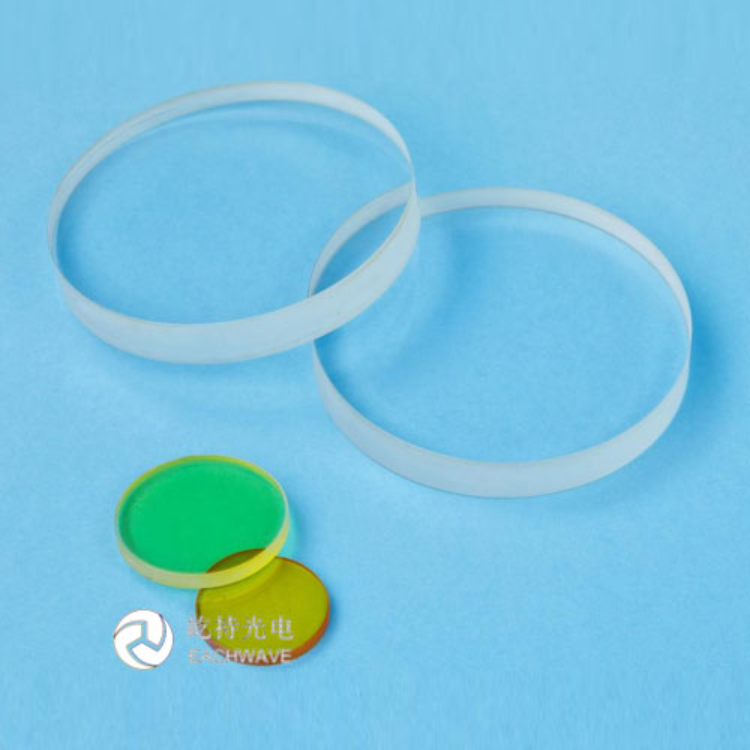
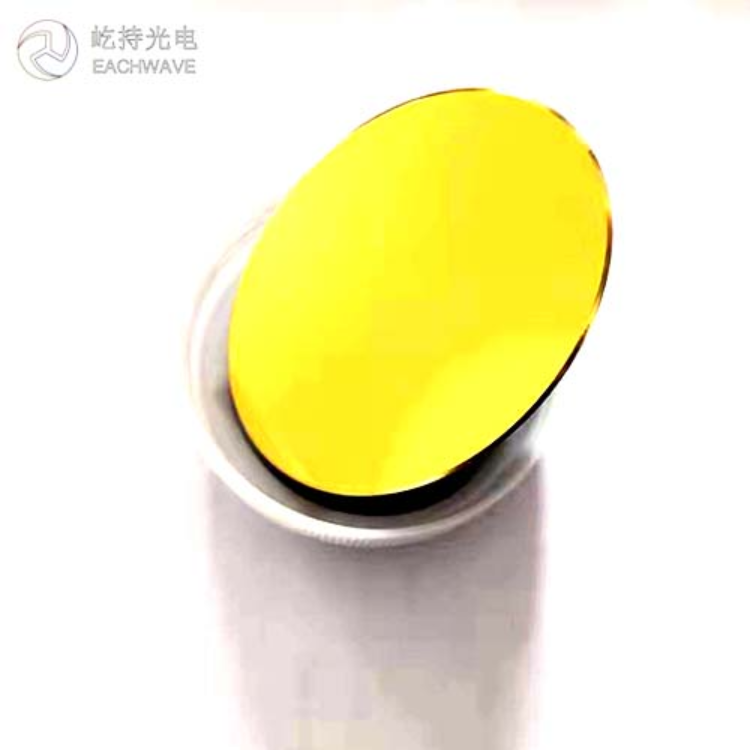
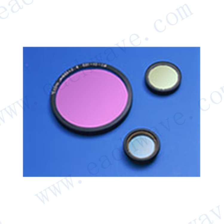
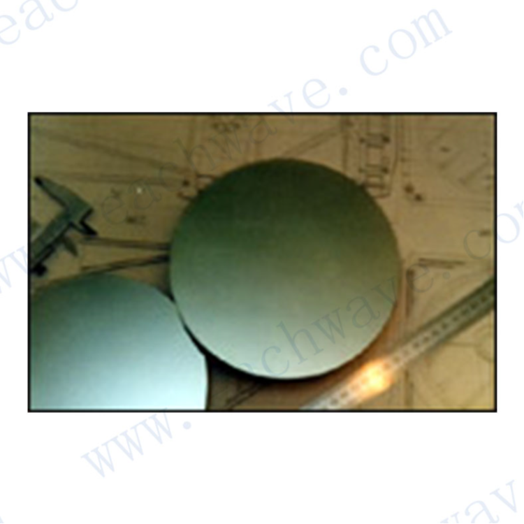
Tydex produces BBAR coated Germanium optics for pyrometry and thermography. All elements are strictly tested to provide the best quality of the material and the coating.
Spectrophotometer measurements
We use the highest optical grade monocristalline germanium for optical production. However, before coating, we always check the transmission of polished windows in the range of 2.0 - 14.0 µm over clear aperture (see Fig. 1).
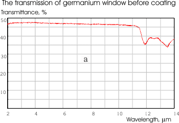
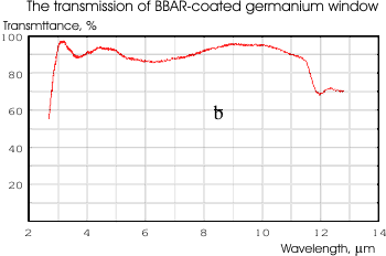
Fig. 1 Transmission spectrum of a Ge window with the diameter of 180 mm and thickness of 12.7 mm
before coating and after deposition of BBAR coating (3.0 - 5.0 µm and 8.0 - 12.0 µm).
Good optical transmission is very important for optical elements; it is the most important parameter for pyrometric applications. However, for the elements of imaging systems it is not enough to have good transmission only. That is why for such elements we carry out more complicated tests.
First, we measure the coefficient of internal scattering. This coefficient determines the part of energy that deviates from incident beam direction after transmitting through the window (routine spectrophotometer measurements cannot separate radiation spreading at different angles). Test beam wavelength is 2.5 µm and it is known that for longer wavelengths scattering losses are smaller. Thus, this coefficient can serve as an adequate parameter for estimation of the material internal quality. The aperture diameter of testing setup is about 35 mm. In cases when it is significantly smaller than the window aperture we measure internal scattering in several spots lying on the perpendicular radii (see Tab. 1 and Fig. 2).
Tab. 1 Coefficients of Internal Scattering at l = 2.5 mm.
Spot # 1 2 3 4 5 6 7 8 9 center R1 R2 R3 R4 1.2% 1.2% 1.3% 1.4% 1.3% 1.4% 1.5% 1.3% 1.6% |
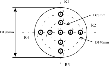
Fig. 2 Scheme of location of internal scattering measurements spots and measurements results.
After that we measure directional transmission at 2.5 µm. This parameter determines the fraction of energy that propagates in the same direction as incident beam. The optical setup for these measurements is constructed in such a way that multiple internal reflections inside the window are eliminated. Testing beam diameter is 5 mm. We provide measurements in several spots as described above. The value of directional transmission for above mentioned window is 40.2 +/- 0.2 % in all spots, which is practically equal to the theoretical maximum.
Finally we measure the transmission of the coated window (see Fig. 1).
Interferometer measurements
For some applications like CO2-laser optics wavefront shape maintenance is very important. For such optics we check transmitted wavefront distortion (TWD) with interferometer measurements using the following procedure:
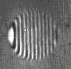
Measured at 10.6 µm, interferometer pattern is transferred to personal computer. At the first stage we remove noise and boost contrast of the image using a regular graphics software (see Fig. 3).
Following operations are performed by a specially designed interferometer graph analysis software. First, we determine the coordinates of fringes. Then we approximate fringes with two-dimensional power polynomials. After that calculation of TWD, parameters and measurements accuracy estimation are provided (see Table 2). Finally we reconstruct wavefront topography and present it on planar and 3-d plots (see Fig. 4).
Fig. 3 Interferometer graph of transmitted wavefront after noise removal and contrast boost. Window with the diameter of 50.8 mm, thickness of 5 mm.
Tab. 2 TWD parameters and measurements accuracy. A window with the diameter of 50.8 mm and thickness of 5.0 mm.
RMSF PVF D B4 PVZ RMS s 0.044 0.26 0.11 0.16 0.12 0.027 0.009 |
RMSF - root mean square wavefront distortion in comparison with the closest plane;
PVF - peak-to-valley wavefront distortion in comparison with the closest plane;
D - focusing coefficient of the sample;
B4 - 4-th order Zernike coefficient of zonal error;
PVZ - peak-to-valley value of zonal error;
RMS(W-Z) - root mean square wavefront distortion without zonal error;
s - wavefront reconstruction inaccuracy;
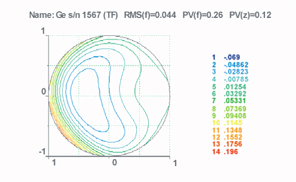
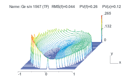
Fig. 4 Reconstructed wavefront topography presented at planar and 3-d plots. Window diameter is 50.8 mm, thickness - 5.0 mm.
TWD depends on material optical homogeneity and flatness of surfaces. Sometimes it is required to separate the contribution of each factor and provide separate data for optical homogeneity and surfaces flatness.
Interferometer measurement of surfaces flatness is provided at 0.633µm, in a phase-measuring regime. Then interferometer graphs are processed in the same way as described above. The data of surfaces flatness is presented in the same form as data of TWD (planar and 3-d plots, table of parameters).
To estimate optical homogeneity we correct TWD by eliminating the error due to surfaces imperfection(see Fig. 5).
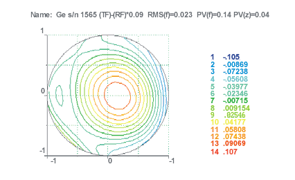
Fig. 5 Reconstructed wavefront compensation of surfaces imperfection presented on a planar plot. Value of TWD over clear aperture 36 mm is equal to 0.14 lambda PVF at 10.6 µm. It corresponds to the value d(n)=3*10-4 over the window aperture. Window diameter = 50.8 mm, thickness = 5.0 mm.
For several applications like CO2-laser output couplers, parallelism of the window surfaces is very critical. Routine mechanical methods do not allow checking of small wedges, as their accuracy is not sufficient. Interferometer methods allow us to measure the wedge value with accuracy of 1.5 seconds of arc.
Lenses
The material control of Germanium lenses is carried out the same way as for the windows. The control of the spherical surfaces accuracy, however, is made with use of the test glasses. For the radii of curvature (ROC) calculation and the production of the lenses we use the list of available test glasses.
Maximal diameter of the lenses that can be processed with the sufficient parameters for the thermography application is 150 mm.
The lenses and the windows can be coated with various types of anti-reflection and protective coatings including hard carbon coating (“diamond-like coating” or DLC).
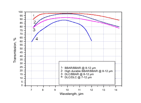
Fig. 6 Comparative transmission curves of Ge windows (4.5mm thick) coated with different types of anti-reflection and protective coatings.