 如何制作一个简易的Sigma Delta ADC?
本文为备战电赛的案例之一,涉及到的知识技能:
FPGA的使用
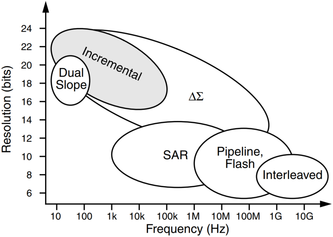
ADC的原理及构成
PWM的产生
比较器的应用
数字滤波器的使用
使用的平台:
多数FPGA芯片上没有ADC的功能,而一些应用则需要用到ADC对一些模拟信号,比如直流电压等进行量化,有没有特别简单、低成本的实现方法呢?
在要求转换速率不高的情况下,完全可以借助一颗高速比较器(成本只有几毛钱)来实现对模拟信号的量化,Lattice的官网上一篇文章就介绍了如何制作一个简易的Sigma Delta ADC,如果FPGA能够提供LVDS的接口,连外部的高速比较器都可以省掉。由于我们的小脚丫FPGA核心模块在设计的时候没有考虑到LVDS的应用场景,所以还是需要搭配一个高速的比较器来实现Lattice官网上推荐的简易Sigma Delta ADC的功能。
让小脚丫FPGA通过锁相环PLL运行于120MHz的主时钟(还可以更高,提速到240MHz、360MHz都应该没有问题),测试1KHz以内的模拟信号是没有问题的。
Lattice的官网上就可以下载到简易Sigma Delta ADC的Verilog源代码,可以非常方便地用在其它品牌、其它系列的FPGA上。
下面的截图就是采用120MHz的主时钟实现的对1KHz模拟信号的采样,并通过DDS/DAC输出,口袋仪器M2000采集并显示的模拟信号波形。
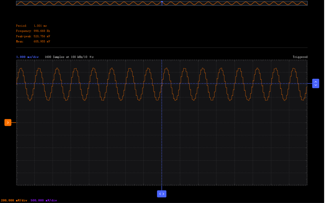
M2000口袋仪器显示的1KHz的波形
详细的工作原理介绍可以参考项目https://www.eetree.cn/project/detail/255 及项目页面中的参考资料,在这里以几幅图片来示例一下。
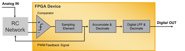
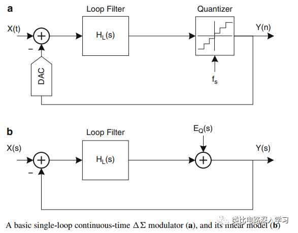
简易Sigma Delta ADC的工作原理
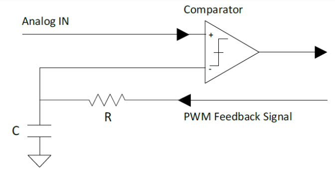
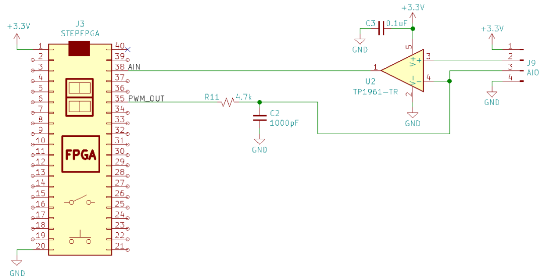
直接连接 - 被测模拟信号的幅度范围为0-3.3V
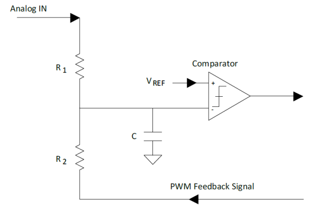
通过电阻分压网络输入,并在比较器+端提供参考电压,则被采集模拟信号的电压变化范围可以扩展

简易Sigma Delta ADC的性能与逻辑电路的工作频率
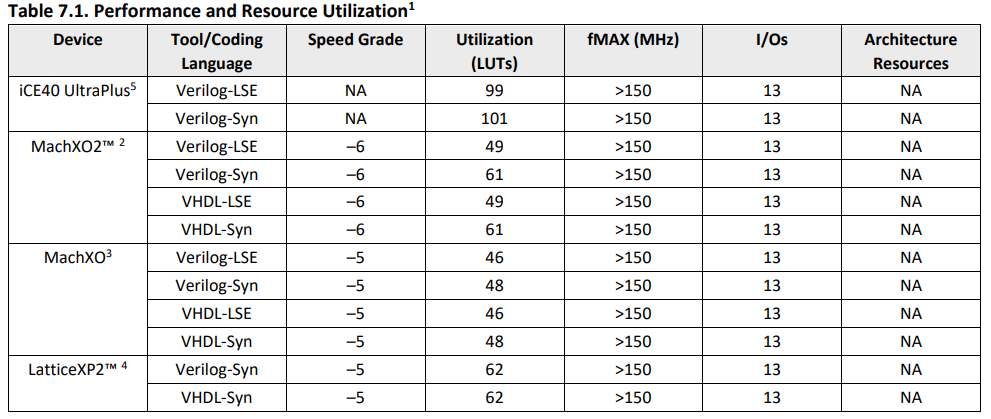
在不同的FPGA平台上消耗的逻辑资源
以下就是我们的电赛综合训练板上简易Sigma Delta ADC部分的电路连接
核心代码:
顶层调用代码:
wire [7:0] sd_adc_out; // sigma delta adc data output
wire sample_rdy; // flag for adc conversion
ADC_top my_adc(.clk_in(clk_hs),.rstn(1‘b1),.digital_out(sd_adc_out), .analog_cmp(comp_in),.analog_out(ad_pwm),.sample_rdy(sample_rdy));
assign dac_data = sd_adc_out;assign dac_clk = clk_hs; //120MHz generated by PLL
Sigma Delta ADC顶层程序
//*********************************************************************//// ADC Top Level Module////*********************************************************************
module ADC_top ( clk_in, rstn, digital_out, analog_cmp, analog_out, sample_rdy);
parameter ADC_WIDTH = 8, // ADC Convertor Bit PrecisionACCUM_BITS = 10, // 2^ACCUM_BITS is decimation rate of accumulatorLPF_DEPTH_BITS = 3, // 2^LPF_DEPTH_BITS is decimation rate of averagerINPUT_TOPOLOGY = 1; // 0: DIRECT: Analog input directly connected to + input of comparitor // 1: NETWORK:Analog input connected through R divider to - input of comp.
//input portsinput clk_in; // 62.5Mhz on Control Demo boardinput rstn; input analog_cmp; // from LVDS buffer or external comparitor
//output portsoutput analog_out; // feedback to RC networkoutput sample_rdy;output [7:0] digital_out; // connected to LED field on control demo bd.
//**********************************************************************//// Internal Wire & Reg Signals////**********************************************************************wire clk;wire analog_out_i;wire sample_rdy_i;wire [ADC_WIDTH-1:0] digital_out_i;wire [ADC_WIDTH-1:0] digital_out_abs;
assign clk = clk_in;
//***********************************************************************//// SSD ADC using onboard LVDS buffer or external comparitor////***********************************************************************sigmadelta_adc #( .ADC_WIDTH(ADC_WIDTH), .ACCUM_BITS(ACCUM_BITS), .LPF_DEPTH_BITS(LPF_DEPTH_BITS) )SSD_ADC( .clk(clk), .rstn(rstn), .analog_cmp(analog_cmp), .digital_out(digital_out_i), .analog_out(analog_out_i), .sample_rdy(sample_rdy_i) );
assign digital_out_abs = INPUT_TOPOLOGY ? ~digital_out_i : digital_out_i;
//***********************************************************************//// output assignments////***********************************************************************
assign digital_out = ~digital_out_abs; // invert bits for LED display assign analog_out = analog_out_i;assign sample_rdy = sample_rdy_i;
endmodule
Sigma Delta ADC主程序
//*********************************************************************//// SSD Top Level Module////*********************************************************************
module sigmadelta_adc ( clk, rstn, digital_out, analog_cmp, analog_out, sample_rdy);
parameter ADC_WIDTH = 8, // ADC Convertor Bit PrecisionACCUM_BITS = 10, // 2^ACCUM_BITS is decimation rate of accumulatorLPF_DEPTH_BITS = 3; // 2^LPF_DEPTH_BITS is decimation rate of averager
//input portsinput clk; // sample rate clockinput rstn; // async reset, asserted lowinput analog_cmp ; // input from LVDS buffer (comparitor)
//output portsoutput analog_out; // feedback to comparitor input RC circuitoutput sample_rdy; // digital_out is readyoutput [ADC_WIDTH-1:0] digital_out; // digital output word of ADC
//**********************************************************************//// Internal Wire & Reg Signals////**********************************************************************reg delta; // captured comparitor outputreg [ACCUM_BITS-1:0] sigma; // running accumulator valuereg [ADC_WIDTH-1:0] accum; // latched accumulator valuereg [ACCUM_BITS-1:0] counter; // decimation counter for accumulatorreg rollover; // decimation counter terminal countreg accum_rdy; // latched accumulator value ’ready‘
//***********************************************************************//// SSD ’Analog‘ Input - PWM//// External Comparator Generates High/Low Value////***********************************************************************
always @ (posedge clk)begin delta 《= analog_cmp; // capture comparitor outputend
assign analog_out = delta; // feedback to comparitor LPF
//***********************************************************************//// Accumulator Stage//// Adds PWM positive pulses over accumulator period////***********************************************************************
always @ (posedge clk or negedge rstn)begin if( ~rstn ) begin sigma 《= 0; accum 《= 0; accum_rdy 《= 0; end else begin if (rollover) begin // latch top ADC_WIDTH bits of sigma accumulator (drop LSBs) accum 《= sigma[ACCUM_BITS-1:ACCUM_BITS-ADC_WIDTH]; sigma 《= delta; // reset accumulator, prime with current delta value end else begin if (&sigma != 1’b1) // if not saturated sigma 《= sigma + delta; // accumulate end accum_rdy 《= rollover; // latch ‘rdy’ (to align with accum) endend
//***********************************************************************//// Box filter Average//// Acts as simple decimating Low-Pass Filter////***********************************************************************
box_ave #( .ADC_WIDTH(ADC_WIDTH), .LPF_DEPTH_BITS(LPF_DEPTH_BITS))box_ave ( .clk(clk), .rstn(rstn), .sample(accum_rdy), .raw_data_in(accum), .ave_data_out(digital_out), .data_out_valid(sample_rdy));
//************************************************************************//// Sample Control - Accumulator Timing// //************************************************************************
always @(posedge clk or negedge rstn)begin if( ~rstn ) begin counter 《= 0; rollover 《= 0; end else begin counter 《= counter + 1; // running count rollover 《= &counter; // assert ‘rollover’ when counter is all 1‘s endendendmodule
数字低通滤波器模块,做平滑滤波
//*********************************************************************//// ’Box‘ Average //// Standard Mean Average Calculation// Can be modeled as FIR Low-Pass Filter where // all coefficients are equal to ’1‘。////*********************************************************************
module box_ave ( clk, rstn, sample, raw_data_in, ave_data_out, data_out_valid);
parameter ADC_WIDTH = 8, // ADC Convertor Bit PrecisionLPF_DEPTH_BITS = 4; // 2^LPF_DEPTH_BITS is decimation rate of averager
//input portsinput clk; // sample rate clockinput rstn; // async reset, asserted lowinput sample; // raw_data_in is good on rising edge, input [ADC_WIDTH-1:0] raw_data_in; // raw_data input
//output portsoutput [ADC_WIDTH-1:0] ave_data_out; // ave data outputoutput data_out_valid; // ave_data_out is valid, single pulse
reg [ADC_WIDTH-1:0] ave_data_out; //**********************************************************************//// Internal Wire & Reg Signals////**********************************************************************reg [ADC_WIDTH+LPF_DEPTH_BITS-1:0] accum; // accumulatorreg [LPF_DEPTH_BITS-1:0] count; // decimation countreg [ADC_WIDTH-1:0] raw_data_d1; // pipeline register
reg sample_d1, sample_d2; // pipeline registersreg result_valid; // accumulator result ’valid‘wire accumulate; // sample rising edge detectedwire latch_result; // latch accumulator result
//***********************************************************************//// Rising Edge Detection and data alignment pipelines////***********************************************************************always @(posedge clk or negedge rstn)begin if( ~rstn ) begin sample_d1 《= 0; sample_d2 《= 0; raw_data_d1 《= 0; result_valid 《= 0; end else begin sample_d1 《= sample; // capture ’sample‘ input sample_d2 《= sample_d1; // delay for edge detection raw_data_d1 《= raw_data_in; // pipeline result_valid 《= latch_result; // pipeline for alignment with result endend
assign accumulate = sample_d1 && !sample_d2; // ’sample‘ rising_edge detectassign latch_result = accumulate && (count == 0); // latch accum. per decimation count
//***********************************************************************//// Accumulator Depth counter////***********************************************************************always @(posedge clk or negedge rstn)begin if( ~rstn ) begin count 《= 0; end else begin if (accumulate) count 《= count + 1; // incr. count per each sample endend
//***********************************************************************//// Accumulator////***********************************************************************always @(posedge clk or negedge rstn)begin if( ~rstn ) begin accum 《= 0; end else begin if (accumulate) if(count == 0) // reset accumulator accum 《= raw_data_d1; // prime with first value else accum 《= accum + raw_data_d1; // accumulate end end //***********************************************************************//// Latch Result//// ave = (summation of ’n‘ samples)/’n‘ is right shift when ’n‘ is power of two////***********************************************************************always @(posedge clk or negedge rstn)begin if( ~rstn ) begin ave_data_out 《= 0; end else if (latch_result) begin // at end of decimation period.。. ave_data_out 《= accum 》》 LPF_DEPTH_BITS; // 。.. save accumulator/n result endend
assign data_out_valid = result_valid; // output assignment
endmodule
原文标题:如何在FPGA上用一个比较器实现ADC的功能?
文章出处:【微信公众号:FPGA入门到精通】欢迎添加关注!文章转载请注明出处。
责任编辑:haq
-
FPGA
+关注
关注
1602文章
21320浏览量
593178 -
adc
+关注
关注
95文章
5651浏览量
539454
原文标题:如何在FPGA上用一个比较器实现ADC的功能?
文章出处:【微信号:xiaojiaoyafpga,微信公众号:电子森林】欢迎添加关注!文章转载请注明出处。
发布评论请先 登录
相关推荐
RZ MPU Delta-sigma的工作原理 Delta-Sigma的应用简介
关于在PSoC 5LP上驱动Delta Sigma ADC的问题求解
请问sigma delta ADC的噪声如何分析?
MAX11214: 24-Bit, 5mW, 140dB SNR, 32ksps Delta-Sigma ADC with Integrated PGA Data Sheet MAX11214: 24-Bit, 5mW, 140dB SNR, 32ksps Delta-Sigma

MAX11208: 20-Bit, Single-Channel, Ultra-Low-Power, Delta-Sigma ADC with 2-Wire Serial Interface Data Sheet MAX11208: 20-Bit, Single-Channel,
ADFS7124-4: 4-Channel, Low Noise, Low Power, 24-Bit, Sigma-Delta ADC with PGA and Reference Data Sheet ADFS7124-4: 4-Channel, Low Noise, Low
ADFS7124-8: 8-Channel, Low Noise, Low Power, 24-Bit, Sigma-Delta ADC with PGA and Reference Data Sheet ADFS7124-8: 8-Channel, Low Noise, Low
AD4129-8:32 微A,超低功率,16-Bit Sigma-Delta ADC,综合PGA和FIFO数据表 ADI
AD4131-8:32 微A,超低功率,16-Bit Sigma-Delta ADC,综合PGA数据表 ADI
AD7124-8:8个通道、低噪音、低功率、24Bit、Sigma-Delta ADC,PGA和参考数据表 ADI
STM32F37x/38x SDADC(Sigma-Delta ADC)入门

增量式Sigma-Delta ADC与传统结构的区别在哪?


 工商网监
工商网监
评论