TI公司的AWR1843是77-79GHz调频连续波(FMCW)雷达传感器,采用TI低功耗45nm RFCMOS工艺制造,具有非常高的集成度和非常小形状系统,工作频段76-81GHz.器件集成了DSP子系统,包含了用于雷达信号处理的高性能的C674x DSP.器件还包括BIST子系统,以进行无线电配置,控制和校准,以及基于用户可编程ARM R4F的汽车接口。具有四个接收通路,三个发送通路,基于分数N PLL的超精度啁啾引擎,TX功率12dBm,RX噪音(76-77GHz) 14dB,主要用在盲区检测,变道辅助系统,路口交通警报,停车辅助系统,占用检测以及简单手势识别和车门开启器应用。本文介绍了AWR1843主要特性,框图,处理器子系统框图,参考电路图以及评估模块AWR1843BOOST主要特性和电路图。
The AWR1843 device is an integrated single-chip FMCW radar sensor capable of operation in the 76- to81-GHz band. The device is built with TI’s low-power 45-nm RFCMOS process and enablesunprecedented levels of integration in an extremely small form factor. The AWR1843 is an ideal solutionfor low-power, self-monitored, ultra-accurate radar systems in the automotive space.
The AWR1843 device is a self-contained FMCW radar sensor single-chip solution that simplifies theimplementation of Automotive Radar sensors in the band of 76 to 81 GHz. It is built on TI’s low-power 45-nm RFCMOS process, which enables a monolithic implementation of a 3TX, 4RX system with built-in PLLand A2D converters. It integrates the DSP subsystem, which contains TI’s high-performance C674x DSPfor the Radar Signal processing. The device includes a BIST processor subsystem, which is responsible for radio configuration, control, and calibration. Additionally the device includes a user programmable ARMR4F based for automotive interfacing. The Hardware Accelerator block (HWA) can perform radarprocessing and can help save MIPS on the DSP for higher level algorithms. Simple programming modelchanges can enable a wide variety of sensor implementation (Short, Mid, Long) with the possibility ofdynamic reconfiguration for implementing a multimode sensor. Additionally, the device is provided as acomplete platform solution including reference hardware design, software drivers, sample configurations,API guide, and user documentation.
AWR1843主要特性:
• FMCW Transceiver
– Integrated PLL, Transmitter, Receiver,Baseband, and A2D
– 76- to 81-GHz Coverage With 4 GHz AvailableBandwidth
– Four Receive Channels
– Three Transmit Channels
– Ultra-Accurate Chirp Engine Based onFractional-N PLL
– TX Power: 12 dBm
– RX Noise Figure:
– 14 dB (76 to 77 GHz)
– 15 dB (77 to 81 GHz)
– Phase Noise at 1 MHz:
– –95 dBc/Hz (76 to 77 GHz)
– –93 dBc/Hz (77 to 81 GHz)
• Built-in Calibration and Self-Test (Monitoring)
– ARM® Cortex®-R4F-Based Radio ControlSystem
– Built-in Firmware (ROM)
– Self-calibrating System Across Frequency andTemperature
• C674x DSP for FMCW Signal Processing
• On-Chip Memory: 2MB
• Cortex-R4F Microcontroller for Object Tracking andClassification, AUTOSAR, and Interface Control
– Supports Autonomous Mode (Loading UserApplication from QSPI Flash Memory)
• Integrated Peripherals
– Internal Memories With ECC
• Host Interface
– CAN (Two Instances, One Being CAN-FD)
• Other Interfaces Available to User Application
– Up to 6 ADC Channels
– Up to 2 SPI Channels
– Up to 2 UARTs
– I2C
– GPIOs
– 2-Lane LVDS Interface for Raw ADC Data andDebug Instrumentation
• ASIL B Targeted
• AECQ100 Qualified
• AWR1843 Advanced Features
– Embedded Self-monitoring With No HostProcessor Involvement
– Complex Baseband Architecture
– Embedded Interference Detection Capability
– Programmable Phase Rotators in Transmit Pathto Enable Beam Forming
• Power Management
– Built-in LDO Network for Enhanced PSRR
– I/Os Support Dual Voltage 3.3 V/1.8 V
• Clock Source
– Supports External Oscillator at 40 MHz
– Supports Externally Driven Clock (Square/Sine)at 40 MHz
– Supports 40 MHz Crystal Connection with LoadCapacitors
• Easy Hardware Design
– 0.65-mm Pitch, 161-Pin 10.4 mm × 10.4 mmFlip Chip BGA Package for Easy Assembly andLow-Cost PCB Design
– Small Solution Size
• Supports Automotive Temperature OperatingRange
AWR1843应用:
• Blind Spot Detection
• Lane Change Assistance
• Cross Traffic Alert
• Parking Assistance
• Occupancy Detection
• Simple Gesture Recognition
• Car Door Opener Applications
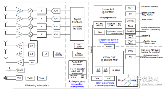
图1.AWR1843框图
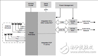
图2.AWR1843汽车应用的自治雷达传感器框图
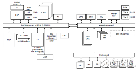
图3.AWR1843处理器子系统框图
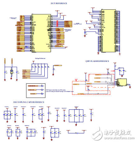
图4.AWR1843参考电路图
图5.AWR1843参考电路图顶层走线图
图6.AWR1843参考电路图顶层走线图特写镜头
图7.AWR1843参考电路图底层走线图
评估模块AWR1843BOOST
AWR1843 Evaluation Module (AWR1843BOOST) Single-Chip mmWave Sensing Solution The AWR1843 BoosterPack™ from Texas Instruments™ is an easy-to-use evaluation board for theAWR1843 mmWave sensing device, with direct connectivity to the microcontroller (MCU) LaunchPad™Development Kit. The BoosterPack contains everything required to start developing software for on-chipC67x DSP core and low-power Arm® R4F controllers, including onboard emulation for programming anddebugging as well as onboard buttons and LEDs for quick integration of a simple user interface.
The AWR1843 BoosterPack from Texas Instruments is an easy-to-use evaluation board for the AWR1843mmWave sensing device, with direct connectivity to the microcontroller (MCU) LaunchPad DevelopmentKit. The BoosterPack contains everything required to start developing software for on-chip C67x DSP coreand low-power ARM R4F controllers, including onboard emulation for programming and debugging as wellas onboard buttons and LEDs for quick integration of a simple user interface.
The standard 20-pin BoosterPack headers make the device compatible with a wide variety of TI MCULaunchPads and enables easy prototyping.
评估模块AWR1843BOOST主要特性:
• Two 20-pin LaundPad connectors that leverages the ecosystem of the TI LaunchPad
• XDS110 based JTAG emulation with a serial port for onboard QSPI flash programming
• Back-channel UART through USB-to-PC for logging purposes
• Onboard antenna
• 60-pin, high-density (HD) connector for raw analog-to-digital converter (ADC) data over LVDS andtrace-data capability
• Onboard CAN-FD transceiver
• One button and two LEDs for basic user interface
• 5-V power jack to power the board
评估模块AWR1843BOOST包括:
• AWR1843 evaluation board
• Mounting brackets, screws, and nuts to place the printed-circuit board (PCB) vertical
• Micro USB cable to connect to PC
图8.评估模块AWR1843BOOST外形图(正面)
图9.评估模块AWR1843BOOST外形图(背面)
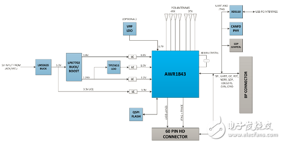
图10.评估模块AWR1843BOOST框图
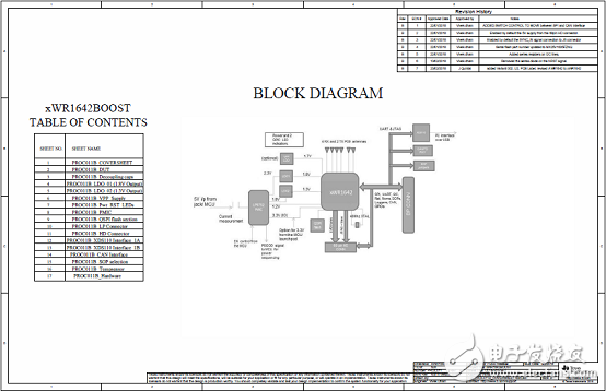
图11.评估模块AWR1843BOOST电路图(1)
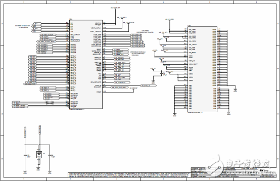
图12.评估模块AWR1843BOOST电路图(2)
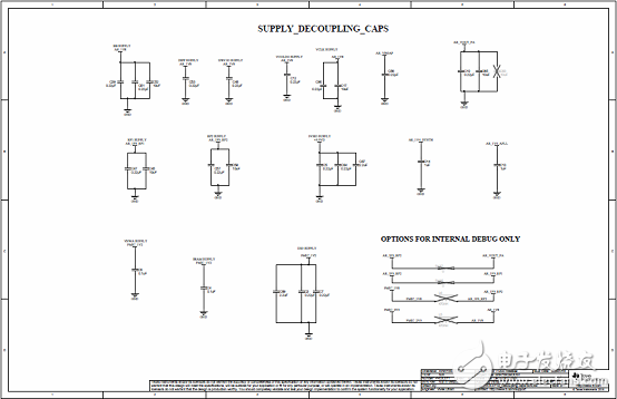
图13.评估模块AWR1843BOOST电路图(3)
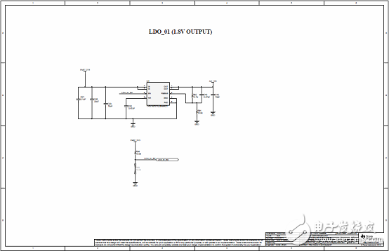
图14.评估模块AWR1843BOOST电路图(4)
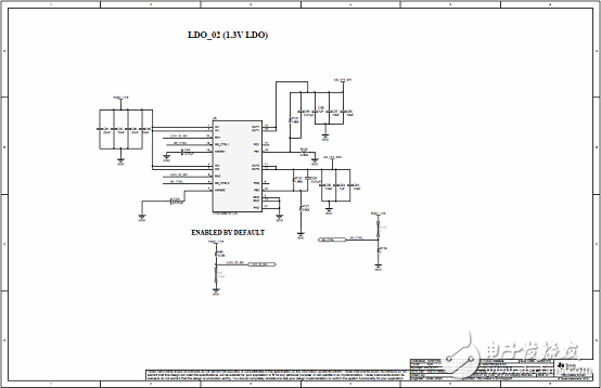
图15.评估模块AWR1843BOOST电路图(5)
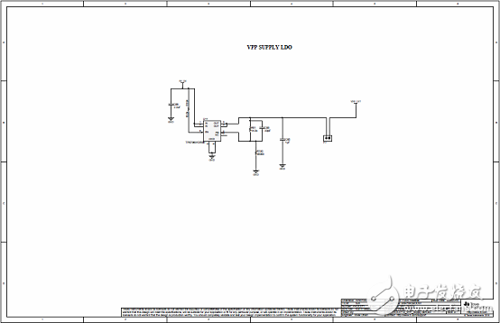
图16.评估模块AWR1843BOOST电路图(6)
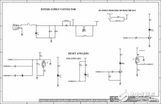
图17.评估模块AWR1843BOOST电路图(7)
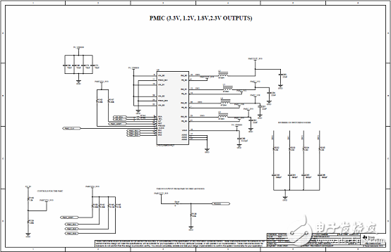
图18.评估模块AWR1843BOOST电路图(8)
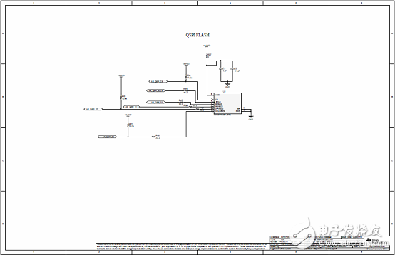
图19.评估模块AWR1843BOOST电路图(9)
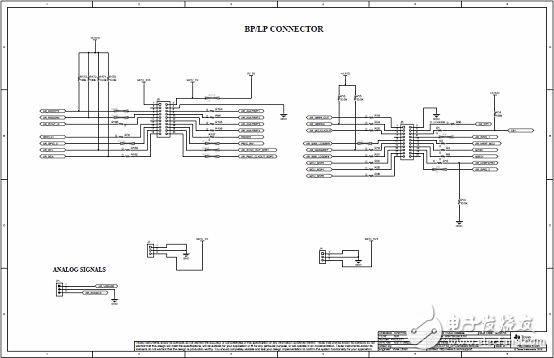
图20.评估模块AWR1843BOOST电路图(10)
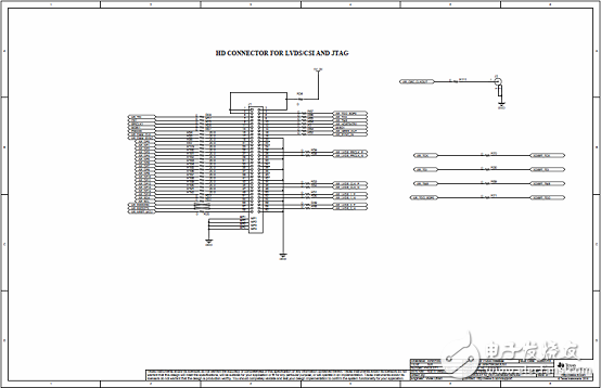
图21.评估模块AWR1843BOOST电路图(11)
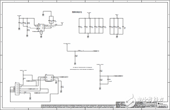
图22.评估模块AWR1843BOOST电路图(12)
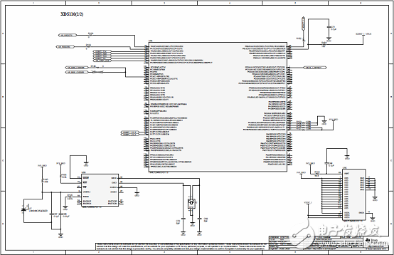
图23.评估模块AWR1843BOOST电路图(13)
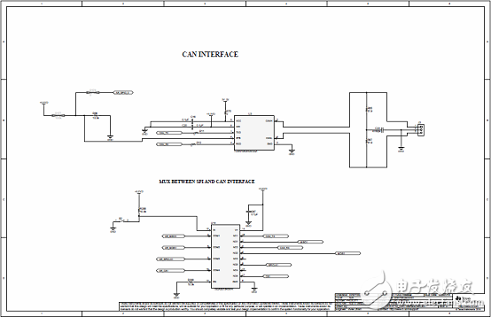
图24.评估模块AWR1843BOOST电路图(14)
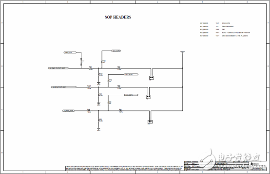
图25.评估模块AWR1843BOOST电路图(15)
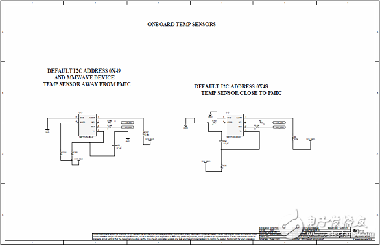
图26.评估模块AWR1843BOOST电路图(16)
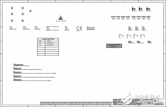
图27.评估模块AWR1843BOOST电路图(17)
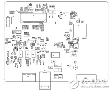
图28.评估模块AWR1843BOOST PCB设计图(1)
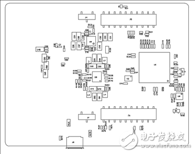
图29.评估模块AWR1843BOOST PCB设计图(2)
详情请见:
和
awr1843.pdf