 高稳定100KHz时钟发生电路,100khz clock generator

高稳定100KHz时钟发生电路,100khz clock generator
关键字:高稳定100KHz时钟发生电路
Build A 100Khz Crystal Calibrator
By N1HFX
There is a great deal of old amateur gear which many amateurs have decided to restore and bring back to life. While much of the early amateur transceivers work just fine they usually lack a digital readout and must rely on analog dials for tuning. The problem of dial calibration is complicated by the non-linear effects of tuning capacitors. This month's circuit is a 100Khz crystal calibrator using an inexpensive microprocessor crystal and CMOS IC's which are readily available at Radio Shack.
The main problem with building a 100Khz oscillator is the unavailability of 100Khz crystals. Even if you find a vendor willing to cut such a crystal for you, plan on paying $20 or more not including shipping charges. The circuit in Figure 1 uses an inexpensive 8Mhz microprocessor crystal which can be easily obtained from most parts suppliers for about $1. Using a 74HCT393 binary counter IC, we can easily divide down the 8 MHz signal from our crystal into 100Khz or almost any frequency we need.
The circuit in Figure 1 uses a couple of NAND gates (74HCT00 IC) for our 8Mhz crystal oscillator. Capacitor C2 actually helps us tune the crystal to the exact frequency, Use any value of C2 from about 22pf to about 82pf to get the oscillator on frequency. In the prototype, 68pf worked fine for most of the crystals tested. For an exact frequency, replace C2 with a 22pf and add a 50pf trimmer capacitor in parallel. By adjusting the 50pf trimmer capacitor, we can easily get the crystal exactly on frequency. The first NAND gate is our oscillator while the second NAND gate acts as a buffer and conditions the signal. This signal is then fed into the clock pulse input of one of the 4 bit binary counters in IC2. By taking the output from the Q3 signal, we have now divided the signal by 16 giving us 500Khz. This signal is now fed into the clock pulse input of the second 4 bit binary counter. In the first counter we tied the MR (clock reset) line to ground. In the second counter, we need the count to reset when we reach a binary five, which will allow us to divide the 500Khz by 5. For this counter, we used the last 2 remaining NAND gates in IC1 to detect the desired value. When we reach the correct reset interval, the MR line goes high resetting the counter to zero and allowing us to effectively divide by 5. The 100Khz output is taken from the Q2 line and is coupled through capacitor C4.
If you prefer, this circuit can be easily changed to a 50Khz calibrator by wiring pins 13 & 14 of IC1 into pins 10 and 8 of IC2. See Figure 2 for details. This arrangement makes the second counter reset at binary 10 which divides the 500Khz by 10 giving us the desired 50Khz.
The HCT series CMOS logic IC's require a 5 volt power supply just like the old TTL logic series. In this circuit we used a 5 volt zener diode, D1, along with resistor R2 to get 12 volts down to 5 volts. Capacitor C3 is used primarily for bypassing the oscillator and must be used in this circuit. If you prefer to power this circuit from a 9 volt battery, then reduce resistor R2 to 220 ohms for best performance.
If you plan to install this circuit inside a transceiver, feed the output directly to the receiver front end. Make certain you have connected it after the TR relay so that the circuit doesn't get zapped by RF from the transmitter side. Also, you will want to install an ON/OFF switch which will interrupt the 12V line going to the circuit. As with all static sensitive CMOS IC's, use special handling precautions and do not leave out those IC sockets.
This circuit has been found to generate accurate birdies at every 100Khz and will be an excellent aid in getting that old rig right on frequency. The accuracy of the 100Khz birdies will depend on how close the 8Mhz oscillator is on frequency. With the difficulty in getting crystals for specific frequencies, this circuit gives new meaning to the words "Divide and Conquer".
要产生100千赫兹频率的电路,如果采用晶体管搭建的LC震荡电路,当要求频率很稳定时比较困难,而采用晶体震荡器则容易实现,而低频率的晶体震荡器又不容易获得,下面的电路就能够将频率较高的晶体震荡器通过适当的电路输出频率较低的信号。
电路原理简单,通过IC1的门电路,晶体以及外围电路组成8M赫兹震荡器,通过IC2分频获得100千赫兹信号。
DE N1HFX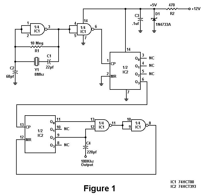
下图是产生50千赫兹的电路,13脚接上图的IC2的6脚就可以了。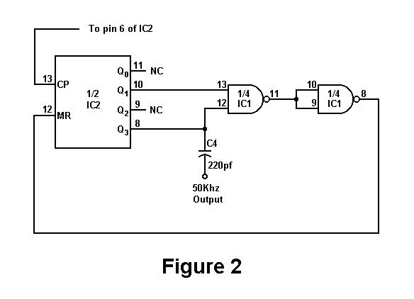
元件清单
Parts List
| C1
声明:本文内容及配图由入驻作者撰写或者入驻合作网站授权转载。文章观点仅代表作者本人,不代表电子发烧友网立场。文章及其配图仅供工程师学习之用,如有内容侵权或者其他违规问题,请联系本站处理。
举报投诉
发布评论请先 登录 相关推荐
热点推荐
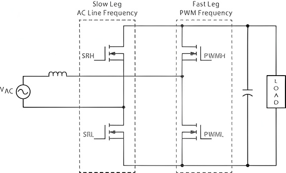
倾佳电子基于SiC MOSFET 的 3kW 高频 (100kHz) CCM 图腾柱 PFC 设计、分析与效率建模倾佳电子基于SiC MOSFET 的 3kW 高频 (100kHz) CCM 图腾柱 PFC 设计、分析与效率建模 倾佳电子(Changer Tech)是一家专注于功率半导体和新能源汽车连
请问如何确定和配置 HRPWM 周期值?你好,我想控制PWM开关频率,精度为10MHz±1%(100KHz)。
PSoC™ Control C3 可以为 PWM 外设提供 240MHz 时钟。因此,通过设置 Period=24,PWM
发表于 08-12 08:24
XL4016是一个180 KHz的固定频率 PWM降压(降压)DC/DC转换器频率振荡器。PWM控制电路能够调节占空比线性从0到100%。一个在内置电流保护功能。当短路保护功能发生时操作频率将从180KHz到48KHz
发表于 07-01 15:18
•0次下载
为什么使用评估板EVAL-AD7760收集的数据中会出现周期性毛刺?为什么使用评估板 EVAL-AD7760 收集的数据中会出现周期性毛刺。以下是无信号输入、差分输入 100kHz、1.35Vpp 正弦波、差分输入 100kHz、2.5Vpp 正弦波的图像(采集了约 8,000,000 个点)。
发表于 04-15 07:41
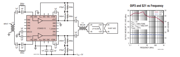
LTC6432-15 100kHz至1.4GHz差分ADC驱动器/IF放大器技术手册。 这款独特的器件能够在 100kHz 至 1GHz 的频段内同时实现低噪声、无可比拟的线性度和平坦的增益。
DLPC350的I2C快速模式无法通信,标准模式不稳定怎么解决?
现象:I2C快速模式400KHZ完全无法通信,DLPC350没有给任何的ACK信号,标准模式100KHZ能正常通信但是不稳定,会出现送出的SUBADDR没有ACK的问题,大部分时候都能正常通信
发表于 02-24 06:25
AD7841需要设置为以100KHZ或者1KHZ采样率对连续128点采样时,应该怎么设置采样率?
您好,我现在在用ADS7841,芯片资料上说它最高可以达到200KHZ的转换率,我想问下 当我需要设置为以100KHZ或者1KHZ采样率对连续128点(或更过点的采样时)采样时,应该怎么设置采样率
发表于 02-07 06:39
ADS1178转换速率是否只与MODE有关,与输入时钟无关?
看了ADS1178的数据手册,输入时钟CLK范围是100kHz到27MHz之间,SCLK推荐为CLK的1、1/2等
问题:
1、转换速率是否只与MODE有关,与输入时钟无关?若设置MODE为0
发表于 01-24 07:21
ads8681标称1mHz的采样率,如果要采样100khz的信号,是否可以正确采样,能否旁路低通滤波器?
请问,ads8681标称1mHz的采样率,但是有个低通滤波器,似乎只能猜到15khz以下的信号,请问如果要采样100khz的信号,是否可以正确采样,能否旁路低通滤波器,谢谢
发表于 12-30 06:47
请问DS90UB903Q的IIC工作频率必须为100KHz吗?
问题:DS90UB903Q的IIC工作频率必须为100KHz吗?
问题发生条件:芯片配置:DS90UB903Q的工作电压为1.8V,VCCIO为3.3V;MODE=1,PDB=1;Rid=0ohm
发表于 12-26 07:08
做一个信号发生器,用FPGA产生正弦数字信号,然后选用DAC8830作为数字转模拟,有杂波的原因?芯片也是隔离开了的
输出100KHz左右的正弦波的时候,有个30KHz的频率
输出90KHz左右的正弦波的时候,有个40KHz的频率
为什么想要的频率跟杂波的频率刚好想加为130
发表于 12-24 06:51
tms320280021 adc采样波形,为什么adc采样频率上来波形就不好了?使用芯片内部ad采样,ad时钟配置为最高100mhz,采样时间配置15时钟周期。timer 200k触发采样,使能dma中断,在dma中断赋值,采样波形乱存在缺相。
设置100khz触
发表于 12-13 16:56
想要测量100KHZ的正弦波的幅值,用ADS1258可以吗?
我想要测量100KHZ的正弦波的幅值,用ADS1258可以吗?是需要先转换成直流然后进行测试吗? 有没有相关的案例,谢谢
发表于 12-13 06:01
DAC7821+OPA277输出信号在10kHz以上失真了怎么解决?
最近尝试使用FPGA制作DDS信号发生器,想要产生频率在100Hz-100kHz可调的正弦波,使用DAC7821+OPA277组合作为DA模块。
在时钟为1MHz时,调节发生的正弦波
发表于 12-10 06:22
版权所有 © 湖南华秋数字科技有限公司 长沙市望城经济技术开发区航空路6号手机智能终端产业园2号厂房3层(0731-88081133) 电子发烧友 (电路图) 湘公网安备43011202000918 工商网监
湘ICP备2023018690号-1 工商网监
湘ICP备2023018690号-1
|


评论