 如何使用Arduino和微型伺服系统制造一个小猫机器人

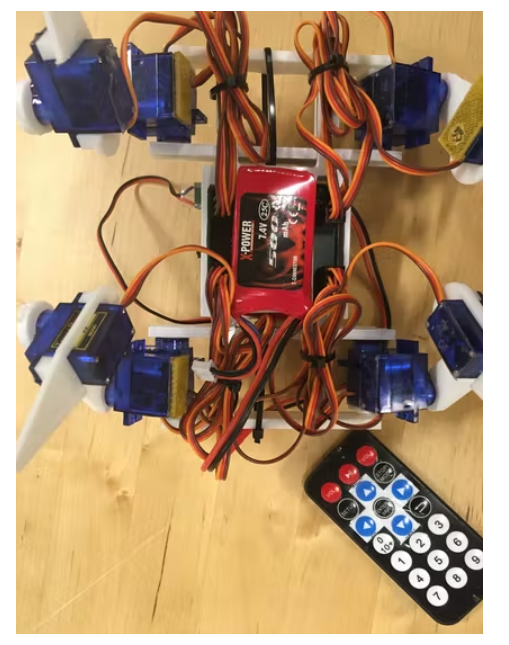
本文要介绍的是一种行走的四足机器人“机器猫”。3DOF 腿,IR 接收器都连接到 Pro Mini。
准备工作
我想做一个四足行走的机器人,更像是“哺乳动物”的风格,而不是普通的“蜘蛛”或“昆虫”。灵感来自著名的波士顿动力机器人和其他四足研究机器人。制作这样的机器人非常具有挑战性,因为它很容易因为重心高和脚在身体下方而翻倒,而不是伸展到角落。
展开来看,最终的目的还是使用 Arduino 和低成本的微型伺服系统制造一个廉价的机器人。这个解决方案当然有它的局限性,不能指望它是完美的。但我今后还准备再设法制造了一些机器人,用很少的预算做最好的事情本身对我来说就是一个挑战。
同时我很早就发现,还需要对反向运动学 (IK) 进行研究以使其正确。该代码具有一组方程式,可根据所需的脚部运动计算关节角度。这些可以进一步用于一些重复性任务的功能,例如进行身体运动(将四只脚向相反方向移动)和进行完整的脚部运动(向上抬起以指定方向移动并再次放下)。
下一个挑战是进行步态研究,即根据身体和足部运动定义机器人应该如何行走和转动。我的机器人一直使用静态稳定的步态。当时一只脚被抬起并放在一个新的位置。身体靠在其他三只脚上,为了不翻倒重心,必须保持在这些脚形成的三脚架内。我开发了四种标准步态——向前、向后、向左和向右。这反过来又利用足部和身体运动功能组合成一个完整的序列。
我还设计了一个同步伺服运动的功能。在某些情况下,几个伺服器在设定的时间内做出不同的冲程。这必须同步以实现平稳的运动。
最后但同样重要的是,我使用了完全不受保护的锂聚合物电池。这可能是有风险的,主要的危险是放电过快或过深。但只要没有意外短路,就可以避免第一个危险。普通 R/C 电池的放电率为 25 C,在这种情况下允许 12 A。UBEC 将防止其在任何情况下高于 2 A。软件中的监视功能可以防止第二种危险。在其中一个模拟引脚上测量电压,如果低于 7.0 V,机器人将停止工作。
我必须强调,电池应该使用专用充电器充电,并应小心处理,切勿让充电无人看管。电池应从机器人上拆下(使用魔术贴安装)并在防火袋中充电,或至少与易燃材料保持安全距离,以免火势蔓延。还要安全地存放电池。
如果您不熟悉 LiPo 电池,请咨询相关行业人士及查阅相关资料并购买电池以及合适的充电器,可能还有用于充电和存放的防火袋/容器。这些物品通常充满警告标志。
构建机器人
首先需要花点时间看一下图片,并在开始之前弄清楚如何组装零件。
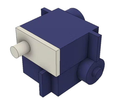
第一步应组装髋关节。我使用质量好的双面胶带连接零件。它们也可以用胶水粘合,但如果需要修复无法拆卸的损坏部件,一个损坏的伺服系统会导致更换整个接头。
将伺服支架放在一个伺服的底部,与驱动轴对齐。然后加入另一个轴垂直的伺服。下图显示了前后左右的髋关节。对于另外两个角,应制作镜像接头。
在继续之前,最好确保所有 12 个舵机都居中。最好的方法是组装 PCB 或面包板(见下文),连接所有伺服系统并加载代码。当 Arduino 启动时,所有舵机将居中(命令信号 90 度)。机器人组装完成后,将需要稍后微调中心位置。
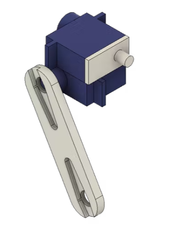
下一步是连接称为大腿的部分,即腿组件的“上肢”。该部件具有与通常与伺服一起交付的伺服喇叭装配在一起的凹槽。将喇叭粘在凹槽中。确保使用胶水来连接 3D 打印材料和喇叭制成的尼龙塑料。
大腿以 60 度角与髋关节相连。当舵机居中时,尝试找到一个尽可能接近该角度的位置。用提供的螺丝(通常是随伺服提供的三个中较短的一个)将喇叭固定到伺服花键上。下面是两张组装好的大腿和臀部的照片,为了清楚起见,伺服喇叭没有包括在内。
腿的下部也应组装。在这种情况下,伺服系统使用螺钉连接到腿部。随伺服提供螺钉(通常是两个较长的“木”螺钉)。
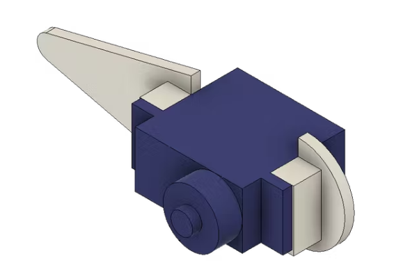
现在可以将腿组装到身体上。我称之为“保险杠”的两个部分位于机器人的前部和后部(就像汽车上的保险杠)。它们有伺服喇叭的凹槽,就像大腿部分一样。将角粘到它们身上。然后将大腿的伺服支撑滑入身体的相应孔中。当这在两侧都完成时,该组件可以由保险杠固定。让腿以大约 12 度的角度向外突出(腿的脚趾向外 20 毫米)。保险杠通过使用剩余的(较长的)伺服螺钉固定在车身上。
最后可以连接机器人的小腿。它们应该与大腿相反的方向倾斜,使脚尖正好位于每个腿组件的髋关节下方。
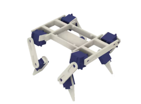
这样机器人就组装好了。它应该如下图所示。机器人的设计与最早的概念相比略有变化。车身经过重新设计,以简化并打造更坚固的设计。髋关节的伺服支撑和喇叭交换了位置。所以根据3D图像组装,避免被照片和电影剪辑混淆。
当然,每个关节的角度不可能完全符合要求的角度,SG-90 舵机上的花键数量为 21,导致两个位置之间的角度为 17 度。您最多可以在 10-20 度范围内组装机器人,剩余的误差必须通过更改代码中的中性位置来调整。再次连接所有伺服系统并启动 Arduino 并检查中性位置并在需要时进行一些机械调整(移动一个或两个样条线)可能是个好主意。与伺服系统一起工作时,往往会意外转动伺服系统。
连接电子设备
有两种选择,将所有东西都放在一个面包板上,或者使用提供的 Fritzing 文件生产 PCB。如果在将所有电源线和地线连接到伺服系统时不小心,您可能会遇到面包板中的电压问题。在极端情况下,一台伺服器可能会消耗 600 mA 的电流,而不良的连接会导致行为不稳定。PCB 的电源线有非常宽的铜迹线,因此如果您正确焊接,它将正常工作。
我的设计中没有电源开关。只需连接电池即可开启和关闭机器人。如果你想添加一个,它应该在电池连接器之后,切断 Arduino 和 UBEC 的 7.4 V 电源。
面包板
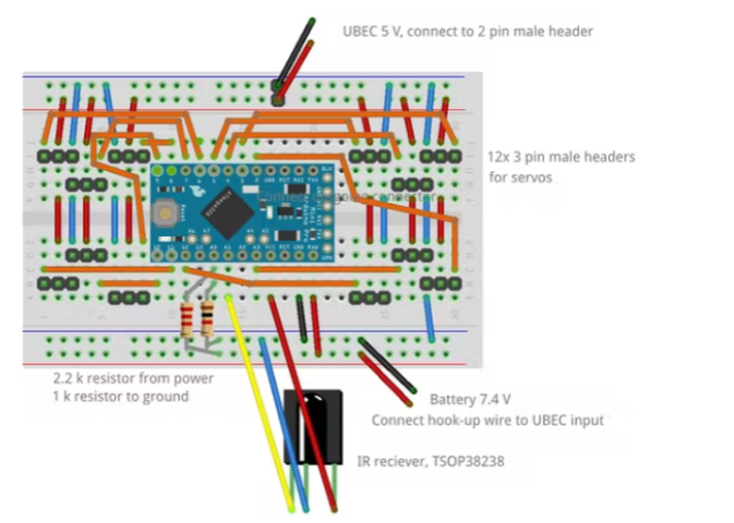
可以将 Pro Mini、伺服连接器和大多数其他电子设备放在一个半尺寸的面包板上。我在下图中绘制了示意图。确保使用短跳线,尤其是用于伺服系统的 5 V 电源和接地连接。伺服连接器只是超长的公头,被切成三块并压入面包板。
图片中没有显示的是电池和UBEC。可能有一些焊接来解决这个问题,以便将连接器配件连接到电池上。从连接器两根跳线应连接到面包板的下部“电源轨”,以便为 Pro Mini 供电(连接到 RAW 和 GND)。还将两个电阻从 7.4 V 电源连接到 A0 引脚。2.2k 来自正极,1k 来自地面。这会将电压(满电池时超过 8 V)分压为低于 5 V 的值,该值可由模拟引脚测量。
UBEC 的输出端有一个伺服连接器。在上面的“电源导轨”上加一个两个公头是相当方便的。把它放在中间的某个地方,如图所示,以确保伺服系统的功率分配尽可能平衡。
IR 接收器应连接到 A1 并具有 5V 电源。接收器上的针脚足够长,可以直接插入面包板上的孔中。
下面有一个示意图和一张关于成品面包板外观的图片。请注意,图片显示了具有不同引脚和连接的旧版本机器人。它仍然提供了如何连接跳线和伺服连接器的想法。
面包板通过其自粘背面连接到车身上。定位它,使伺服系统连接到引脚 D3、D4 和 D5(示意图中的右上角)的角位于机器人的前/左角,并确保电路板位于身体的中心(正确的中心重力至关重要)。
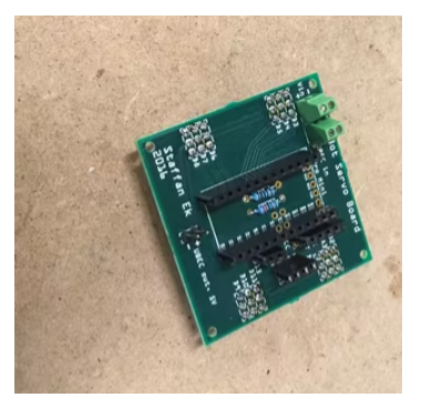
PCB
PCB 是为这个机器人定制的,带有连接到所有伺服、IR 和电压测量的连接器。但也有从其余引脚断开的连接器。如果您将来想扩展机器人,这些可用于连接其他设备。
身体上有一些小的“垫子”,可以贴合 PCB 的角落。同样在这里,带有 D3 到 D5 连接器的角落应该在前面/左侧。PCB上有安装孔,但我只在机身上使用了一块双面胶带来固定它。它会留在原地。
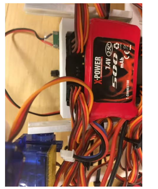
电池
电池用魔术贴固定在底部。身体上有专门用于此的平面。7.4V/500mAh LiPo 电池的外形尺寸通常约为 55x30x10 mm(上下几毫米),非常适合这个地方。
最后,机器人可以通过将伺服线捆成漂亮的束来“修饰”,这样它在行走时就不会被它们绊倒。它还使机器人看起来实际上是一个四足行走的生物,而不是一堆伺服线。
敲定环节
在使用机器人之前,应微调中心位置。这是通过在代码中编辑数组 serverdeg0 来完成的:
const float servodeg0[12] = {90, 90, 90, 90, 90, 90, 90, 90, 90, 90, 90, 90};
这些值的顺序是 alfa、beta gamma 和前/左、后/左、前/右、后/右。所以右前方的 beta 是数组中的第八个位置或者是serveddeg0[7](数组的编号从 0 开始)。
还有一个称为servodir 的数组定义了舵机的旋转方向。
const int servodir[12] = { +1, +1, -1, -1, -1, +1, -1, -1, -1, +1, +1, +1}; // Turning direction (positive is servo counter-clockwise)
我使用的舵机逆时针方向从 0 度移动到 180 度。我在某处读到有伺服系统朝另一个方向前进。在这种情况下,数组servodir 必须始终更改其符号。
启动 Arduino 并检查所有伺服系统的角度。采取措施,看看一切看起来都是直的和对称的。距离和角度应根据下图。
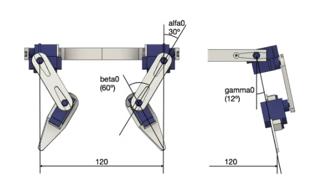
每次测量很难在精确的毫米范围内,在厘米范围内是合理的。查看需要哪些更改并将它们添加/减去数组servodeg0中的值。在一切正确之前,这肯定需要几次迭代。你将以一个看起来像这样的servodeg0数组结束(我的一个机器人的一段实际代码)。最重要的是,你最终应该拥有一个四足支撑并笔直站立的机器人。
const float servodeg0[12] = {80, 95, 100, 100, 110, 90, 100, 115, 100, 80, 80, 100};
不过需要记住的是,一段时间后,伺服系统可能需要重新校准。中心位置会随着时间而漂移。只需不时检查所有内容是否对齐。
如果您已将所有步骤都正确执行,但仍有一个机器人会翻倒,请检查重心。可以移动电池来平衡这一点,使用魔术贴是一件好事。
注意:小心对待你的锂聚合物电池
未来的进一步改进
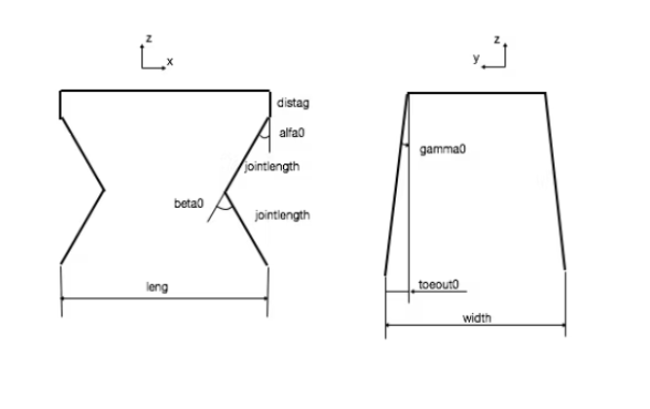
通过在这里讲述我的机器人后,我还邀请了人们改进设计,或者添加更多功能,或者做一个稍微不同的布局(更大、更小、更酷)。该代码应该可以在布局或大小略有不同的机器人上重复使用。下面的草图显示了代码中的不同常量。如果制造了具有不同措施的机器人,所有 IK 和运动功能应该仍然有效。它还显示坐标已定义,x 指向正向。
当然,如果你愿意为这个机器人添加更多功能那会很有趣。遥控器上有几个按钮可以被赋予功能。
我个人尝试模拟输入。我还使用了“走路时转身”的步态,以便能够在一定程度上引导机器人,或者在陀螺仪或指南针的帮助下纠正路线偏差。我还添加了一个超声波传感器和自主行为(避开障碍物)。不过目前的项目是将模拟控制与自主相结合,并通过智能手机控制一切。
代码部分:
/* An IR controlled version of the KITtyBot 2.
It uses Arduino Pro Mini and the PCB board designed by me (Fritzing sketch Kittybotmini.fzz)
It is based on the previous robots KITtyBot and KITtyBot mini using an IR remote to control the robot
It uses a NEC (Adafruit) remote and the IRLib2 libraries, see https://github.com/cyborg5/IRLib2.
Download IRLib2 libraries from the repository and install them according to the instructions.
The general dimensions are similar to the original KITtyBot but there is a displacment
between the gamma and alfa axis of 12 mm (the servos mounted on top of each other)
I have conitiously tweeked the gaits for walking and turning but I so far feel this has given the most stable behaviour.
Created by Staffan Ek 2017
*/
#include
#include
#include
#include
#define MY_PROTOCOL NEC //Defines the IR control (NEC)
long Previous;
IRrecv My_Receiver(A1);//Receive on pin A0
IRdecodeNEC My_Decoder;
const int servonum = 12; // The amount of servos
Servo servo[servonum]; // Create servo object
const float servodeg0[12] = {90, 90, 90, 90, 90, 90, 90, 90, 90, 90, 90, 90};
// Neutral positions for the servos adjusted from nominal 90 degrees (a calibration is needed to adjust these values)
float servodegnew[servonum]; // The desired servo position in degrees
float servodegold[servonum]; // The old (or current) servo position
// Update values below to the KITtyBot mini
const int servodir[12] = { +1, +1, -1, -1, -1, +1, -1, -1, -1, +1, +1, +1}; // Turning direction (positive is servo counter-clockwise)
const float pi = 3.1416;
const float alfa0 = pi / 6; // The neutral position of alfa (30 deg)
const float beta0 = pi / 3; // The neutral position of beta (60 deg)
const float jointlength = 50; // The length of a leg part (both have the same length)
const float width = 120; // The width (distance between feet in y direction, with toeout0 added)
const float leng = 120; // The length (disatnce between feet in x direction)
const float distag = 12; // Distance between alfa and gamma axis
const float toeout0 = 20; // The outward distance of feet from the gamma servo centre (the distance the foot is pointed outwards)
const float leglength0 = 2 * jointlength * cos(alfa0);
const float gamma0 = asin(toeout0 / (leglength0 + distag)); // The neutral position of gamma (due to toe out 20 mm and distag 12 mm)
const float bodyradius = sqrt(pow((width / 2), 2) + pow((leng / 2), 2)); // The length of diagonal (distance from centre to foot corner)
const float phi0 = atan(width / leng); // The angle of bodyradius vs the x (forward pointing) axis
const float height0 = sqrt(pow(leglength0 + distag, 2) - pow(toeout0, 2)); // The normal height of robot (if any angles or distances are changed this must be updated)
float leglength [4] = {sqrt(pow(height0, 2) + pow(toeout0, 2)), sqrt(pow(height0, 2) + pow(toeout0, 2)),
sqrt(pow(height0, 2) + pow(toeout0, 2)), sqrt(pow(height0, 2) + pow(toeout0, 2))
};
// Start values of leglength
unsigned long timestep = 500; // Time taken by each sequence (when using servomove())
int steplength = 40; //The length of a step in x direction during walking (forward and reverse creep)
float phi = 20; // turnangle during turning (in degrees, not radians!)
// Variable for movement
float footpos[12]; // Foot positions, order LeftFrontxyz, LeftRearxyz, RightFrontxyz, RightRearxyz
float stepturn[12] = {0, 0, 0, 0, 0, 0, 0, 0, 0, 0, 0, 0}; // Foot movement in case of a turn
// The foot positions are calibrated with their respective start positions
const float jointangle0[12] = {alfa0, beta0, 0, alfa0, beta0, 0, alfa0, beta0, 0, alfa0, beta0, 0};
float jointangle[12]; //Using a vector for angles, order LeftFrontAlfaBetaGamma etc
const int voltagepin = A0; // The assigned pin for voltage meassure
int lowvolt = 0; // A variable that stops the robot if the voltage goew <7.0 V
int mode = 0; // The current ordered walking mode; forward, reverse, left, right
void setup() {
Serial.begin(9600);
Serial.println("KITtyBot mini"); //These lines are just to check the configuration. Can be deleted.
Serial.print("Gamma0: ");
Serial.println(gamma0);
Serial.print("Leglength0: ");
Serial.println(leglength0);
Serial.print("Bodyradius: ");
Serial.println(bodyradius);
Serial.print("Phi0: ");
Serial.println(phi0);
Serial.print("Height0: ");
Serial.println(height0);
servo[0].attach(3);
servo[1].attach(4);
servo[2].attach(5);
servo[3].attach(6);
servo[4].attach(7);
servo[5].attach(8);
servo[6].attach(2);
servo[7].attach(A3);
servo[8].attach(12);
servo[9].attach(11);
servo[10].attach(10);
servo[11].attach(9);
for (int i = 0; i < servonum; i++) { // Centre all values and the output to the serovs
servodegnew[i] = servodeg0[i];
servodegold[i] = servodegnew[i];
servo[i].write(servodegnew[i]);
}
delay(5000);
My_Receiver.enableIRIn(); // Start the receiver
}
void loop() {
voltmeasure(); // Check voltage at least here
while (lowvolt == 0) { // Proceed only if there is enough power
bodyxyz(0, 0, 0); // Just make sure everything is centered
servomove();
mode = 0;
IRread();
Serial.print("Mode: "); // Only for monitoring in the serial console, can be deleted
Serial.println(mode);
switch (mode) {
case 1: forwardcreep(); break;
case 2: reversecreep(); break;
case 3: leftturn(); break;
case 4: rightturn(); break;
}
voltmeasure();
delay(500);
}
if (lowvolt == 1) { // Got to "rest". A clear signal that battery needs charging
bodyxyz (0, 0, -30); // Lower body, a clear signal that it has gone to rest
servomove();
}
}
// Below are the functions called in correct order in order to calculate new angles
void lengthangles() {
// Front left foot
jointangle[2] = gammaleft(footpos[1], footpos[2]);
leglength[0] = legleft(footpos[0], footpos[2], jointangle[2]);
jointangle[1] = beta(leglength[0]);
jointangle[0] = alfafront(footpos[0], jointangle[1], leglength[0]);
// Rear left foot
jointangle[5] = gammaleft(footpos[4], footpos[5]);
leglength[1] = legleft(footpos[3], footpos[5], jointangle[5]);
jointangle[4] = beta(leglength[1]);
jointangle[3] = alfarear(footpos[3], jointangle[4], leglength[1]);
// Front rigth foot
jointangle[8] = gammaright(footpos[7], footpos[8]);
leglength[2] = legright(footpos[6], footpos[8], jointangle[8]);
jointangle[7] = beta(leglength[2]);
jointangle[6] = alfafront(footpos[6], jointangle[7], leglength[2]);
// Rear right foot
jointangle[11] = gammaright(footpos[10], footpos[11]);
leglength[3] = legright(footpos[9], footpos[11], jointangle[11]);
jointangle[10] = beta(leglength[3]);
jointangle[9] = alfarear(footpos[9], jointangle[10], leglength[3]);
}
// Functions used to calculate IK
// Gamma, the hip servo "on top"
float gammaleft (float dy, float dz) {
float gresult = atan((toeout0 + dy) / (height0 - dz)) - gamma0;
return gresult;
}
float gammaright(float dy, float dz) {
float gresult = gamma0 - atan((toeout0 - dy) / (height0 - dz));
return gresult;
}
//Calculating leg length (distance alfa axis to toe)
float legleft(float dx, float dz, float gamma) {
float lresult = sqrt(pow(leglength0 - (dz / cos(gamma0 + gamma)), 2) + pow(dx, 2));
if (lresult > 2 * jointlength) lresult = 2 * jointlength; // If leglength is higher than possible some following functions become unstable
return lresult;
}
float legright(float dx, float dz, float gamma) {
float lresult = sqrt(pow(leglength0 - (dz / cos(gamma0 - gamma)), 2) + pow(dx, 2));
if (lresult > 2 * jointlength) lresult = 2 * jointlength; // If leglength is higher than possible some following functions become unstable
return lresult;
}
// Beta, the "knee joint"
float beta(float leg) {
float bresult = 2 * acos(leg / (2 * jointlength));
return bresult;
}
// Alfa, The other hip servo
float alfafront(float dx, float beta, float leg) {
float aresult = (beta / 2) - asin(dx / leg);
return aresult;
}
float alfarear(float dx, float beta, float leg) {
float aresult = (beta / 2) + asin(dx / leg);
return aresult;
}
// Giving foot positions based on a turning angle f (in degrees). Stepturn is the used to make footpos values
void turnpos(float f) {
stepturn[0] = bodyradius * cos(phi0 + (f * pi / 180)) - leng / 2;
stepturn[1] = bodyradius * sin(phi0 + (f * pi / 180)) - width / 2;
stepturn[3] = bodyradius * cos(pi - phi0 + (f * pi / 180)) + leng / 2;
stepturn[4] = bodyradius * sin(pi - phi0 + (f * pi / 180)) - width / 2;
stepturn[6] = bodyradius * cos(2 * pi - phi0 + (f * pi / 180)) - leng / 2;
stepturn[7] = bodyradius * sin(2 * pi - phi0 + (f * pi / 180)) + width / 2;
stepturn[9] = bodyradius * cos(pi + phi0 + (f * pi / 180)) + leng / 2;
stepturn[10] = bodyradius * sin(pi + phi0 + (f * pi / 180)) + width / 2;
}
// Calculates servo positions (in degrees) based on joint angles in the fucntion above
void servopos() {
for (int i = 0; i < 12; i++) {
servodegnew[i] = servodeg0[i] + servodir[i] * (jointangle[i] - jointangle0[i]) * 180 / pi;
}
}
// The servo algorithm for controlled and syncronized movements. All servos should reach their end position at the end of a timestep
void servomove() {
int servotimeold[servonum]; // Local variable for time of last servo position
int servotimenew[servonum]; // Local variable for the current time when the servo i positioned
int SERVOPULSE[servonum]; // Local variable to write to the servo driver
float servodeg[servonum]; // Local variable for the current servo position
float servodegspeed[servonum]; // Local variable for the desired servo speed degress per millisecond
unsigned long starttime = millis(); // Time stamp the start of the algorithm
unsigned long timenow = starttime; // Resetting time now
for (int i = 0; i < servonum; i++) {
servodegspeed[i] = (servodegnew[i] - servodegold[i]) / timestep; // Calculate the desired servo speed
servodeg[i] = servodegold[i]; // Resetting the servo position
servotimeold[i] = starttime; // Resetting the time
}
while ((timenow - starttime) < timestep) { // Loop continues until the time step is fulfilled
for (int i = 0; i < servonum; i++) { // Iterate through each servo
servotimenew[i] = millis(); // Get a time stamp
servodeg[i] += servodegspeed[i] * (servotimenew[i] - servotimeold[i]);
// Calculate a new position based on the desired speed and elapsed time
servo[i].write(servodeg[i]); // Position servo
servotimeold[i] = servotimenew[i]; // Resetting the old servo time for the next iteration
}
timenow = millis();
// Get a time stamp after all servos has been iterated to use in the while case.
}
for (int i = 0; i < servonum; i++) { // Make on last iteration to assure that the servos reached their end positions
servo[i].write(servodegnew[i]); // Position servo
servodegold[i] = servodegnew[i]; // Resetting the current position for future iterations
}
}
// A servomove without timing, use when no synchronous moving is needed, i.e. lifting/moving one leg
void servomovefast() {
for (int i = 0; i < servonum; i++) { // Make on last iteration to assure that the servos reached their end positions
servo[i].write(servodegnew[i]); // Position servo
servodegold[i] = servodegnew[i]; // Resetting the current position for future iterations
}
delay(100); // Just give a reasonable time for servos to reach endpoint before moving on.
}
// Calculates a foot position (xyz coordiantes)
void footxyz(int i, float x, float y, float z) {
footpos[3 * i] = x;
footpos[3 * i + 1] = y;
footpos[3 * i + 2] = z;
lengthangles();
servopos();
}
// Calculates foot movement, adding desired value to current position
void footmovexyz(int i, float x, float y, float z) {
footpos[3 * i] += x;
footpos[3 * i + 1] += y;
footpos[3 * i + 2] += z;
lengthangles();
servopos();
}
// Calculates body positioning according to xyz coordinates.
void bodyxyz(float x, float y, float z ) {
//Note: Moving body means moving the feet in the other direction, hence minus signs in all foot positions
for (int i = 0; i < 4; i++) {
footpos[3 * i] = -x;
footpos[3 * i + 1] = -y;
footpos[3 * i + 2] = -z;
}
lengthangles();
servopos();
}
// Calculates body movement, adding cooridinate to existing position.
void bodymovexyz(float x, float y, float z ) {
//Note: Body move mean moving the feet in the other direction, hence minus signs in all foot positions
for (int i = 0; i < 4; i++) {
footpos[3 * i] -= x;
footpos[3 * i + 1] -= y;
footpos[3 * i + 2] -= z;
}
lengthangles();
servopos();
}
// Calculates a twist on the body the desired angle phi
void bodytwist(float f) {
// Again here the movement is in minus driection from the foot positions
turnpos(-f);
for (int i = 0; i < 12; i++) {
footpos[i] += stepturn[i];
}
lengthangles();
servopos();
}
// Does a footmovement; lifts move xy and puts down foot
void footstep (int i, float x, float y) {
footmovexyz(i, 0, 0, 30);
servomovefast();
footmovexyz(i, x, y, 0);
servomovefast();
footmovexyz(i, 0, 0, -30);
servomovefast();
}
// Does a footmovement based on the disired turning angle, moves the foot along the turning arc
void (footstepangle(int i, float f)) {
turnpos(f);
footmovexyz(i, 0, 0, 30);
servomovefast();
footmovexyz(i, stepturn[3 * i], stepturn [3 * i + 1], 0);
servomovefast();
footmovexyz(i, 0, 0, -30);
servomovefast();
}
// Checks voltage, in case of low battery lowvolt variable changes
void voltmeasure() {
/* Note: The 7.6 V battery is conneced via a 2.2k resistance from BAT to voltagepin and 1.0k to GND
This gives the 5 V analog input a 16 volt measure range*/
float voltsig = analogRead(voltagepin);
float voltage = voltsig * 16 / 1023.0;
Serial.print("Battery: ");
Serial.println(voltage);
if (voltage < 7.0) {
lowvolt = 1;
}
else {
lowvolt = 0;
}
}
// The IR read function, based on Adafruits example sketch
void IRread() {
if (My_Receiver.getResults()) {
Serial.print("Recieving ");
Serial.println (My_Decoder.value);
if (My_Decoder.decode()) {
if (My_Decoder.value == 0xFFFFFFFF) { // Detects if the button is still pressed and keeps the value
My_Decoder.value = Previous;
}
switch (My_Decoder.value) { //Detects if an arrow button is pressed and sets mode parameter
case 0xfda05f: mode = 1; break;
case 0xfdb04f: mode = 2; break;
case 0xfd10ef: mode = 3; break;
case 0xfd50af: mode = 4; break;
}
Previous = My_Decoder.value;
}
My_Receiver.enableIRIn();
}
else {
mode = 0;
}
}
// A gait for forward creeping
void forwardcreep() {
bodymovexyz(steplength / 4, -toeout0, 0); // Starts to position for forward walking, leaning to the right
servomove();
footstep(1, steplength / 2, 0); // Moving rear left leg one half step length
footstep(0, steplength / 2, 0); // And the front left
bodymovexyz(steplength / 4, 2 * toeout0, 0); // Shifting body forward and to the left (in order to move the right feet later)
servomove();
while (mode == 1) {
// Here the while loop starts, repeaetd as long as fwd is ordered (mode 1)
footstep(3, steplength, 0); // Moving rear right forward
footstep(2, steplength, 0); // Moving front right forward
bodymovexyz(steplength / 2, -2 * toeout0, 0); // Shifting body forward and to the right
servomove();
footstep(1, steplength, 0); // Moving rear left forward
footstep(0, steplength, 0); // Moving front left forward
bodymovexyz(steplength / 2, 2 * toeout0, 0); // Shifting body forward and to the left
servomove();
// The robot has the same position as before the while loop but has moved on steplength forward.
IRread(); // If there is still a forward command (mode ==1) the sequence should be repeated
}
// The while loop ends and it assumes normal postion
/* bodymovexyz(0, 10, 0);*/
footstep(3, steplength / 2, 0); // Taking half steps to make all legs neutral
footstep(2, steplength / 2, 0);
bodyxyz(0, 0, 0); // Centering body
servomove();
// Leaving gait mode
}
// A similar gait for reverse walking (not commented as much look at forwardcreep
void reversecreep() {
bodymovexyz(-steplength / 4, -toeout0, 0); // Starts to position for forward walking
servomove();
footstep(0, -steplength / 2, 0);
footstep(1, -steplength / 2, 0);
bodymovexyz(-steplength / 4, 2 * toeout0, 0);
servomove();
while (mode == 2) {
// Here the while loop starts, repeaetd as long as reverse is ordered (mode 2)
footstep(2, -steplength, 0);
footstep(3, -steplength, 0);
bodymovexyz(-steplength / 2, -2 * toeout0, 0);
servomove();
footstep(0, -steplength, 0);
footstep(1, -steplength, 0);
bodymovexyz(-steplength / 2, 2 * toeout0, 0);
servomove();
IRread(); // If mode == 2 the while loop continues
}
// The while loop ends and it assumes normal postion
/* bodymovexyz(0, 10, 0);*/
footstep(2, -steplength / 2, 0);
footstep(3, -steplength / 2, 0);
bodyxyz(0, 0, 0);
servomove();
// Leaving gait mode
}
// Doing a turn to the left the desired phi angle
void leftturn() {
while (mode == 3) {
// While loop as long as the left button is pressed
bodyxyz(toeout0 / 2, toeout0, 0); // Lean left before doing anything
servomove();
footstepangle(3, phi); // Move rear right foot into new position
footstepangle(2, phi); // Move front right foot into new position
footxyz(0, -toeout0 / 2 - stepturn[0], toeout0 - stepturn[1], 0);
footxyz(1, -toeout0 / 2 - stepturn[3], toeout0 - stepturn[4], 0);
footxyz(2, -toeout0 / 2, toeout0, 0);
footxyz(3, -toeout0 / 2, toeout0, 0);
// Twisting body and lean left. Written in absolute coordinates to minmize errors.
servomove(); // Do the actual servo command
footstepangle(0, phi); // Move front left foot
footstepangle(1, phi); // Move rear left foot
IRread(); // Check is left button is still pressed (mode == 3), repeat while loop
}
bodyxyz(0, 0, 0); // Centre body when turning is finished
servomove();
}
//Doing a right turn. Should be identical to left turn but with different commands. Testing both at the moment.
void rightturn() {
while (mode == 4) {
// While loop as long as the right button is pressed
bodyxyz(-toeout0 / 2, toeout0, 0); // Lean left before doing anything
servomove();
footstepangle(2, -phi); //Move front right foot
footstepangle(3, -phi); //Move rear right foot
footxyz(0, toeout0 / 2 - stepturn[0], toeout0 - stepturn[1], 0);
footxyz(1, toeout0 / 2 - stepturn[3], toeout0 - stepturn[4], 0);
footxyz(2, toeout0 / 2, toeout0, 0);
footxyz(3, toeout0 / 2, toeout0, 0);
// Twisting body and lean left. Written in absolute coordinates to minmize errors.
servomove(); // Do the actual servo command
footstepangle(1, -phi); //Move rear left foot
footstepangle(0, -phi); //Move front left foot
IRread(); // Check is rightt button is still pressed (mode == 4), repeat while loop
}
bodyxyz(0, 0, 0);
servomove();
}
-
机器人
+关注
关注
213文章
30580浏览量
219532 -
伺服系统
+关注
关注
14文章
594浏览量
41507 -
Arduino
+关注
关注
190文章
6515浏览量
195956
发布评论请先 登录
基于DSP的机器人视觉伺服系统设计
机器人视觉伺服系统的标定
机器人伺服系统详解(组成/原理框图/执行元件/发展趋势)
工业机器人专用伺服系统市场概况
PLC的工业机器人关节直流伺服系统


 工商网监
工商网监
评论