 如何通过代码HodgePodging加快最大步进速度

第1步:
我使用了很多单词来描述我的方法,但是我也尊重每个人都会从另一个地方来处理这个问题。如果您有经验,请多说些抱歉,但是,如果您不熟悉arduino,并且想以比当前使用accelstepper更快的速度运行步进电机,那么请问所有问题。
计划:
Accelstepper使用非线性加速度曲线,以逐渐增加步进电机的步进率。它在stepper.run()调用期间以非常抽象的方式执行此操作,这是一个(粗略的想法)函数,用于检查您是否应进行新步骤,如果是,则步进驱动程序并计算下一次执行的时间步骤已到。您需要经常调用它,但是您可以在控制循环中执行其他操作。因此,例如,在这里您可能会看到:
同时(digitalRead(someSensor)== high){
//做东西
//做更多东西
stepper.run();
}
只要“填充”时间不长,stepper.run()就会非常频繁地运行,并且步进操作。但是stepper.run()并不是一个非常快速的函数,在某些时候它是限制因素!然后,此while循环会花费太长时间。
所以我的建议和方法是执行以下操作:
//starting from the non-moving position
while(condition){
//do stuff
stepper.run();
if (stepper.Speed()==maxAccelstepperSpeed){
//Extrafast mode is a simple linear acceleration program. Not as nice as stepper.run(), but much faster.
break; //let‘s get out of this while loop!
}
//extraFastMode()伪代码:
//calculate a starting stepdelay based on what speed you’re transitioning away from the accelstepper library.
The new method of stepping will just be:
“While(condition){
”Do stuff/ check extra if statements
Take a step
wait manually with a delay
add to a counter
//if the counter hits a trigger number, and you‘re not at your final target speed,
then decrease your delay [which increases your motor speed“
}//loop back to the top
这有意义吗?下一步,让我们深入研究同样冗长的注释代码,如果有任何问题,请返回。
步骤2:哇,代码!
我从我的项目中提取了一个完整的程序,并在保留大部分表单的同时将其剥离了下来。 “功能”模式。我可以说原始代码有效,但是我只测试了新代码可以编译。
此代码是否完美?否。
此代码是执行此操作的最佳还是最快方法?否。
但这行得通吗?是。我希望我已使其功能尽可能透明。
它最初是作为函数调用编写的,在我的程序中可以使用几个不同的马达(调用accellstepper的不同实例),但在此示例中我将其简化了一些。
建议:如果签出附带的.ino,则可以在您喜欢的文本编辑器中查看代码。它的显示效果会好得多,我不建议整体复制此代码块,因为它可能会稍微变形。
/*This document should end up as a short introduction to one particular method of
sidestepping Accelstepper’s somewhat low step-rate limit using default stepper.run()
protocol. It is not the only and certainly not the best method. But it works.*/
//Extra note about the purpose: This lets you use the nice accelstepper acceleration
algorithm for the initial acceleration and then a much cruder linear ramp thereafter.
#include
const int stepPin=23;
const int directionPin=14;
/*Accelstepper SetMotorIdentifier(TYPE, STEP, DIRECTION) We are using type 1 because I‘m using a classic STEP/DIR stepper Driver.
Different types might ask for things other than step&direction [see Accelsteppr documentation]*/
AccelStepper stepper(1,stepPin,directionPin);
long actuatorDistance = 158400; //This varies depending on your purpose. I wanted to go 158,400 steps. That corresponded with 99 rotations of my 1.8 deg stepper motor with 1/8th microstepping.
int actuatorSpeed=3900; //This corresponded to 487.5 steps/second, or 2.47 revs/second, which for me corresponding to about 40 seconds for my actuator.
unsigned long actuatorTimeout =19000; //This might not be used in the tutorial, but it’s good to have a timeout threshold if you think your actuator might stall out and you want some backup timeout.
int actuatorAcceleration=8500; //This acceleration value was chosen by experimentation, and only corresponds to the initial actuatorSpeed trigger point - after that your linear acceleration takes over.
const byte programOverhead=26; //measured in mS.
//During the fast-stepping function you may want to check a few sensors (in my case, for an end-stop)。 The thing is you want your initial linear step-delay to be pretty close to whatever step rate the accelstepper actuatorSpeed was. For this to work, you need to know roughly how much time your control loop takes excluding the step delay. If your sketch is similar to mine in what it‘s checking, you can start with my numbers.
const byte minPulseWidth=3; //different drivers require different minimum step pulses to register a line change.。.The basic reprap drivers are 1-2mS, this is sort of an unnecessary variable I used for extra fluff, you can probably do without it.
//FINAL STEP RATE VALUE
byte stepDelayTarget=90-minPulseWidth-programOverhead; // This should never add up to 《0. Check manually.
//This number, here shown as 90, relates to your target final step max speed. 90 is in uS, so I went up to 1000,000/90 = 11,111.1.。 steps/second. That’s an improvement over the default max of 3900 steps/seconds and was rate limited in my application by the physical system. I don‘t know how high you can expect an arduino to go. I would guess around 30uS for the mega with my specific code (ergo 33,000 steps/s)
const int systemEndstop=24;
const int enablePin=53; //This is another extra variable I kept in the example code. You can ignore it, but it refers to a pin that is controlling the enable pin of my DRV8825 driver. Because it’s 53 you can see I wrote this probably for an arduino mega.
//Global variables as part of the program functions.
unsigned long timeStart; //We want to be able to reset timeStart in different parts of the program. It‘s a global variable redeclared by a number of functions. Be aware. Another ’extra variable‘ I kept in the example code.
void setup(){ //Void setup runs once during initial boot of microprocessor, but not after.
stepper.setPinsInverted(false,false,true); // setPinsInverted(bool Dir,bool Step,bool Enable) Bool enable is == true because my enable pin is OFF when HIGH and ON when LOW. This is opposite of the default, so we enable the invert function. I believe the default is set for an A4988 driver, and this use case is for the Pololu DRV8825 breakout.
//the following should be familiar if you’ve used the accelstepper program before.
stepper.setMaxSpeed(actuatorSpeed);
stepper.setAcceleration(actuatorAcceleration);
stepper.setEnablePin(enablePin);
stepper.setMinPulseWidth(3); //Remember the minPulseWidth variable from before? This is the accelstepper version.
// declare pinmodes
pinMode(systemEndstop,INPUT);
digitalWrite(systemEndstop,HIGH); //This sets internal 20k pull-up resistor. It is usually necessary for a hall sensor to have a pull-up resistor, and in this case I was using a hall-sensor endstop.
} //end of void setup
void fastSteppingFunction(){ //This function will be used later as the linear-ramp portion of the code.
//Ok! StepDelay needs to be set so that it creates a stepping speed approximately equal to the stepping speed that accelstepper leaves off at. Much different, and you will have caused an instantaneous acceleration that the stepper motor will fail to keep up with.
byte stepDelay=((1000000/actuatorSpeed)-minPulseWidth-programOverhead);
//IMPORTANT NOTE: If your actuatorSpeed is less than 3900steps/s, you might want to change stepDelay to a uint_16t or otherwise ”uint.“ Bytes are less overhead to work with, but can‘t be 》255
//In my original code, I actually hard coded the stepDelay start at 250 instead of (100000/actuatorSpeed)。 The math for my values would put 1,000,000/actuatorSpeed at 256 steps/second, and for some reason I chose 250. But this math step allows for you to change your actuatorSpeed without needing to change the value here.
byte counter = 0;
//counter is used as a way to make a very quick conditional statement that overflows every 256 digits. There are other ways to implement the linear ramp. This is the way I chose. I thought it would be fast although it’s no longer clear to me why I chose exactly this method.
while(digitalRead(systemEndstop)==HIGH){ //remember this is our ending condition. In my code we are not relying on our steps to be counted. You can count steps too, by setting your condition to be when a bigger counter reaches a certain number. Then you need to implement a counter that increments during each step.
digitalWrite(stepPin,HIGH);
delayMicroseconds(minPulseWidth);
digitalWrite(stepPin,LOW);
delayMicroseconds(stepDelay);
if (actuatorTimeout《(millis()-timeStart)){ //Did you notice we said ”timeStart=millis()“ at the start of actuation? This is because I recommend your system has a timeout in case your motor stalls out and you never reach your endstop.
//make an error function and call it here.
//make a function to get back up to speed, assuming you want to do that after you resolve the error. Optional not included.
//recursively return to the fastSteppingFunction();
}
/*Next step is to increment the counter. This will run each time you repeat the loop.
My method is not very adjustable to changing the slope of the ramp, and if I were to rewrite
this code today I would probably choose something else. Consider this when implementing
your code.
*/
counter=counter+2; /*always manipulate this counter so that you understand when your
counter will reach the condition in the if statement below. In my case, it will reach the
the condition every 256/2 steps, i.e, every 128 steps. If I chose a number like ”3“ instead
of ”2“ I would have a problem because the counter would not reach 0 until a third overflow
of the byte counter, so I would be decreasing the slope of my linear ramp six times.
Meanwhile I can also decrease the slope by half by changing the number to 1. Or, I can double
the slope by saying 4. This lack of flexibility in changing the linear ramp slope is why
I suggest considering other methods to make a linear ramp. Try to implement your method with
minimum math. Ideally do not include multiplication in the loop, and especially not division.
*/
if (stepDelay》stepDelayTarget && counter==0){ //So this condition is looking to see if you‘re reached your max speed target, and if you haven’t yet and the counter has reached its trigger point [0], then it decreases the delay.
stepDelay--; //Stepdelay-- is a fast way of saying ”stepdelay=stepdelay-1“, i.e, your decreasing the step delay. By decreasing the step delay, you are increasing the frequency of steps/ the speed of your motor.
}
}
}
}
void moveActuatorForward(){
//Hey! You‘re about to start moving a motor. In a lot of cases that means you should make some safety check. The following commented if statement is a filler for that.
/*if ([insert errorCondition]){
//stepper.disableOutputs();
//error();
}*/
stepper.enableOutputs(); //This is redundant, in fact. It’s already been called.
stepper.move(actuatorDistance); //You need to tell accelstepper how far you‘re going!
timeStart = millis(); //I used a global variable in other parts of the code, maybe you want to use a local variable.
//Hey we’re finally starting!!
while(1){ //Title: ”Basic Moving While Loop“
if (digitalRead(systemEndstop)==LOW){ //checks if we hit the endstop before reaching the accelstepper max speed
//This never happened for my application, but maybe does for yours.
break; //break removes you from the while loop called ”Basic Moving While loop“
}
stepper.run(); //this makes your initial acceleration completely abstract.
if(stepper.speed() fastSteppingFunction();
break;
}
}
stepper.DisableOutputs();
//Hey we‘re done!
}
void loop(){
//do stuff other than moving your motors, if you have other stuff to do.
stepper.disableOutputs(); //I tend to add extra disableOutputs in case I made mistakes in the code, because my stepper motors were set to a high current that would eventually make those little motors overheat. For simple programs this isn’t a big deal, but once you start running around with more program states you want to be sure you don‘t let your motor overheat while you’re doing something else.
if (1){ //Here I‘m just suggesting that you probably want to run the actuator based on some condition.
//Now this is a stripped version of the code. Let’s just look at it as a goal to ”actuate“ a linear actuator. There are two endstops for this device but we‘re only looking at moving the actuator from ”home“ to ”endstop“
stepper.enableOutputs();
stepper.setCurrentPosition(0); //My physical system had a lot of friction, so I never decelerated my load. This meant that when I start the motor, accelstepper sometimes wants to ”slow down“ before it accelerates again. This is even if it was in fact not running. SetCurrentPosition(0) acts as a reset to the accelstepper code.
moveActuatorForward();
stepper.disableOutputs();
}
}
步骤3:PS,您注意到了吗?
我的“线性斜坡”实际上不是线性斜坡。我每128步(大约每20mS)减少1uS步之间的延迟。最初,步进延迟为250mS,步进增加的速率为每32mS 1uS。到我的驱动结束时,每11.5mS的增加速率为1uS。这是一个非线性的斜坡,在接近终点时加速度增加。可能有很多很好的方法可以使此线性化,或更改执行速度增加的方法。但是我的执行器已经运行了好几个月,所以我认为该方法已经足够好了。
事实是,直到我编写此可指导的代码并梳理我的代码之前,我才注意到它。
责任编辑:wv
-
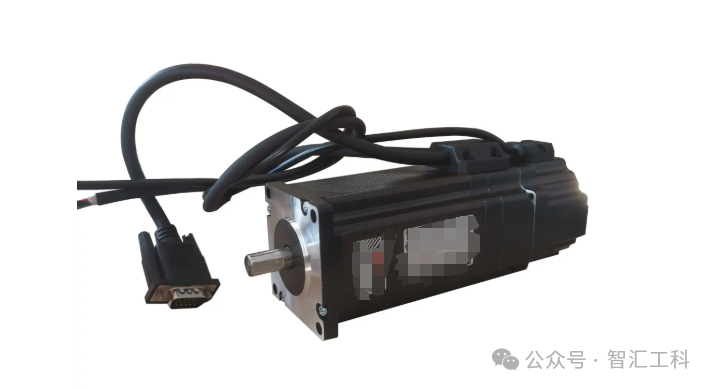
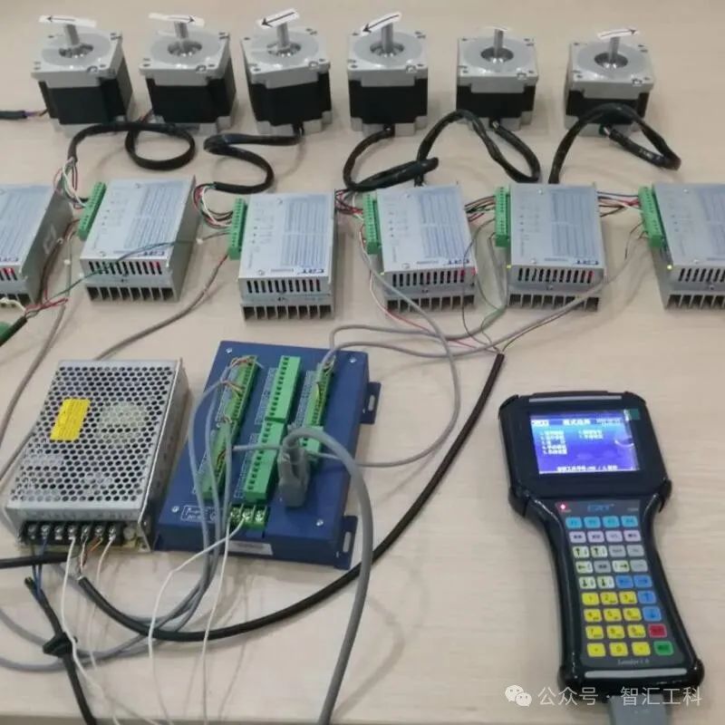
步进电机
+关注
关注
152文章
3216浏览量
151555
发布评论请先 登录
STM32IDE如何设定代码到ITCM中运行?
步进电机和伺服电机的区别是什么?
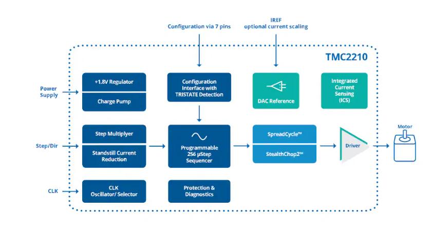
ADI Trinamic TMC2210大电流步进电机驱动器IC数据手册
关于范例fifosync5bit在使用EP1-8共有16个通道时,其最大速度能达到多少K?
实时生成步进电机速度曲线
刹车步进电机的特点
步进电机过载怎么处理
网络笔记分享-实时生成步进电机速度曲线
MATLAB中的simulink中仿真速度过慢,状态量数值很小可以忽略,怎么忽略较小数值,加快仿真进度呢?
步进电机的控制实现方法

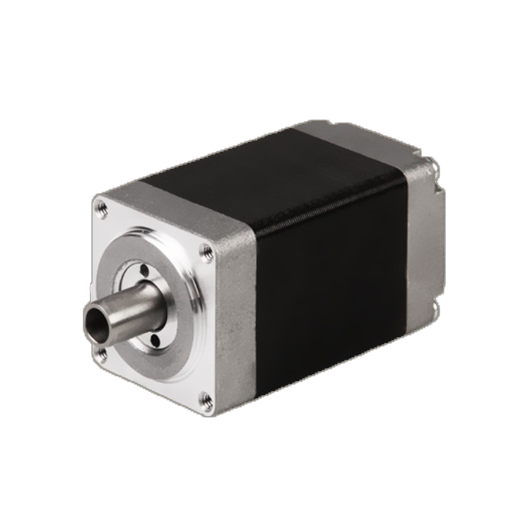
中空轴步进电机概述
通过具体案例,选择合适的步进电机
EMC整改的六大步骤


 工商网监
工商网监
评论