 IFX007T大电流半桥马达驱动器介绍
infineon公司的IFX007T是集成的大电流半桥马达驱动器,是工业和多用途NovalithIC™系列的一部分,在同一封装内包括一个P沟高边MOSFET和一个N沟低边MOSFET以及集成的驱动器。由于P沟高边开关不需要充电泵,因此最小化EMI;由于集成的驱动器IC,具有逻辑电平输入,电流检测诊断,转换速率调整,死区时间产生和对超温,欠压和过流与短路的保护,因此和MCU的接口变得很容易,为保护大电流PWM马达驱动提供非常小板空间的成本最优化解决方案.@25℃时的最大通路电阻12.8 mΩ,高边最大为6.5 mΩ,低边最大为6.3 mΩ,限流水平为55A,具有闩锁特性和欠压关断特性,工作电压高达40V,JESD47I资格,IFX007T和其它IFX007T组成H桥或其它3相驱动配置,主要用在马达驱动。本文介绍了IFX007T主要特性,框图和应用电路,以及IFX007T马达控制板主要特性,Arduino马达控制电路图和PCB布局图。
The IFX007T is an integrated high current half bridge for motor drive applications. It is part of the Industrial &Multi PurposeNovalithIC™ family containing one p-channel high-side MOSFET and one n-channel low-sideMOSFET with an integrated driver IC in one package. Due to the p-channel high-side switch the need for acharge pump is eliminated thus minimizing EMI. Interfacing to a microcontroller is made easy by the integrated driver IC which features logic level inputs, diagnosis with current sense, slew rate adjustment, deadtime generation and protection against overtemperature, undervoltage, overcurrent and short circuit.
The IFX007T provides a cost optimized solution for protected high current PWM motor drives with very lowboard space consumption.
The IFX007T is part of the Industrial &Multi PurposeNovalithIC™ family containing three separate chips in onepackage: One p-channel high-side MOSFET and one n-channel low-side MOSFET together with a driver IC,forming an integrated high current half-bridge. All three chips are mounted on one common lead frame, using the chip-on chip and chip-by-chip technology. The power switches utilize vertical MOS technologies to ensureoptimum on state resistance. Due to the p-channel high-side switch the need for a charge pump is eliminatedthus minimizing EMI. Interfacing to a microcontroller is made easy by the integrated driver IC which featureslogic level inputs, diagnosis with current sense, slew rate adjustment, dead time generation and protectionagainst overtemperature, undervoltage, overcurrent and short circuit. The IFX007T can be combined withother IFX007Ts to form a H-bridge or a3-phase drive configuration.
IFX007T主要特性:
• Path resistance of max. 12.8 mΩ @ 25℃ (typ. 10.0 mΩ @ 25℃)
High side: max. 6.5 mΩ @ 25℃ (typ. 5.3 mΩ @ 25℃)
Low side: max. 6.3 mΩ @ 25℃ (typ. 4.7mΩ @ 25℃)
• Enhanced switching speed for reduced switching losses
• Capable for high PWM frequency combined with active freewheeling
• Switched mode current limitation for reduced power dissipation in overcurrent
• Current limitation level of 55 A min.
• Status flag diagnosis with current sense capability
• Overtemperature shutdown with latch behavior
• Undervoltage shutdown
• Driver circuit with logic level inputs
• Adjustable slew rates for optimized EMI
• Operation up to 40 V
• Green Product (RoHS compliant)
• JESD47I Qualified
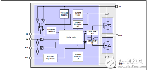
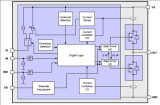
图1. IFX007T框图
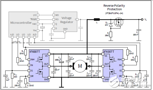
图2. IFX007T应用电路:两个IFX007T组成H桥
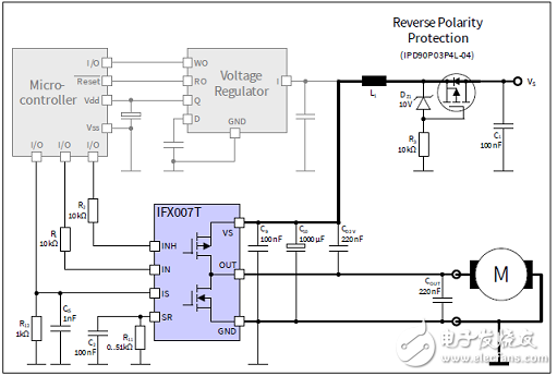
图3. IFX007T应用电路:IFX007T(负载接地)组成半桥
IFX007T马达控制板
The Motor Control Shield adds powerful motor control to the Arduino projects. The shield can be controlledwith the general logic IO-Ports of a microcontroller. Either an Arduino Uno or the XMC1100 Boot Kit fromInfineon can be used as the master.On board of the Motor Control Shield are three IFX007T NovalithICTM. Each is featuring one P-channel high sideMOSFET and one N-channel low side MOSFET with an integrated driver IC in one package. Due to the P-channelhigh side switch a charge pump is not needed.
The IFX007T half-bridge is easy to control by applying logic level signals to the IN and INH pin. When applying aPWM to the IN pin the current provided to the motor can be controlled with the duty cycle of the PWM. With anexternal resistor connected between the SR pin and GND the slew rate of the power switches can be adjusted.The Motor Control Shield can be easily connected to any Arduino board or the XMC1100 Boot Kit via headers.
The application targeted by the IFX007T devices is brushed DC/brushless DC Motor Control. Besides MotorControl any other inductive, resistive and capacitive load within the electrical characteristics of the NovalithIC™can be driven by the IFX007T. In the Motor Control Shield three IFX007T are used. Each is capable of driving up to 55 A. The limited thermal performance of the Shield PCB limits the recommended maximum current to 30 A.
图4. IFX007T马达控制板外形图
IFX007T马达控制板主要特性:
• An Arduino Uno, XMC1100 Boot Kit, or similar board connected to the shield can control the three halfbridgesvia the general IO pins.
• Brushed DC Motor Control up to 250 W continuous load
- 8 – 24 V nominal input voltage (max. 6 – 40 V)
- Average motor current 30 A restricted due to the limited power dissipation of the PCB (IFX007T currentlimitation @ 55 A min.)
• Drives either one brush/less DC motor, one brushed bi-directional DC motor or three uni-directional DCmotors.
• Capable of high frequency PWM, e.g. 25 kHz
• Adjustable slew rates for optimized EMI by changing external resistor
• Driver circuit with logic level inputs
• Status flag diagnosis with current sense capability
• Protection e.g. against overtemperature and overcurrent
• Reverse polarity protection with IPD90P04P4L
• Further comments:
- Due to limited performance caused by the PCB layout, we recommend our customers to remove thecapacitance C5 for high frequency applications. It is only layout related, not refer to the device.
- The size of the DC-link capacity (C4 in schematic) with 560 μF is for most applications sufficient. But forhigh current applications, we recommend our customers to follow the design rule in our applicationnote and replace the DC-link cap with a bigger one.
- Due to the limited area of the PCB and the small DC-link cap, the demoboard shouldn ’t be used forshort circuit test.
- This demoboard is designed for both sensorless applications and the application with Hall sensor. Butfor the application with sensor, please remove R36/R37/R38 and solderR18/R19/R20/R21/R22/R23/R25/R26/R27.
- Due to the limited pinout of the Arduino shield all IS pins of the three devices are connected together.
According to different applications the value of R4 could be adjusted to achieve a better current senseperformance.
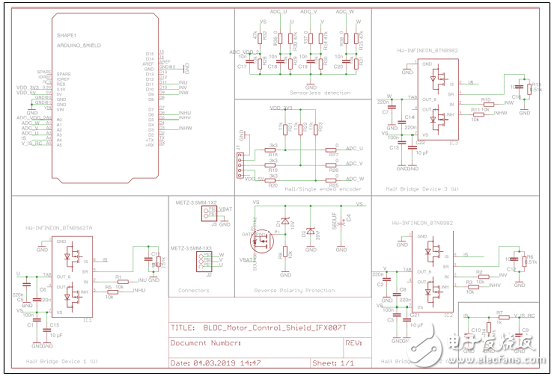
图5.采用IFX007T的Arduino马达控制电路图
图6.采用IFX007T的Arduino马达控制板PCB布局图
图7.马达控制板连接器
详情请见:
https://www.infineon.com/dgdl/Infineon-IFX007T-DS-v01_00-EN.pdf?fileId=5546d46265f064ff0166433484070b75
和https://www.infineon.com/dgdl/Infineon-Motor_Control_Shield_with_IFX007T_for_Arduino-UM-UM-v01_00-EN.pdf?fileId=5546d462694c98b401696d2026783556
Infineon-IFX007T-DS-v01_00-EN.pdf
Infineon-Motor_Control_Shield_with_IFX007T_for_Arduino-UM-UM-v01_00-EN.pdf
-
驱动器
+关注
关注
51文章
7305浏览量
142916 -
马达驱动器
+关注
关注
0文章
26浏览量
15720
发布评论请先 登录
相关推荐
【转帖】如何实现隔离式半桥栅极驱动器?
实现隔离式半桥栅极驱动器的设计基础
基于隔离式Fly-Buck电源的半桥MOSFET驱动器
LT1160的典型应用:半桥/全桥N沟道功率MOSFET驱动器
论文分享《LLC详谈细谈-新型LLC自驱动半桥谐振变换器研究》
电机控制的半桥栅极驱动器FD6288T和Pt*5619完成兼容、电动工具桥驱动
DRV8313半桥驱动器中文资料
IR2111半桥驱动器相关资料分享
浅析FD2606S半桥栅极驱动器
FAN73832 具有可变死区时间和关断保护 半桥栅极驱动器IC
Infineon IFX007T大电流BLDC马达控制方案


 工商网监
工商网监
评论