 Arduino学习指南
简介
您来对地方了:)
从地铁实验者指南开始!
Adafruit Metro和Metro Express的实验者指南旨在为制作者,艺术家,黑客,学生,教育工作者,或想开始使用Metro或Metro M0 Express的任何人。
本指南中有许多电路,可让您熟悉诸如学习不同类型的电子组件等技能(以及它们的工作方式),对Adafruit Metro或Metro Express进行编程,面包板和修改代码。
已经有可以通过Arduino IDE编程的零件和板上了吗?该指南也将为您服务!
按照本指南的顺序进行操作,您将对Adafruit Metro感到满意,足以完成自己的项目(或者至少足以尝试Adafruit学习系统中数千个项目之一)
关于实验者指南
实验者指南是Oomlout的awesomeARDX套件的扩展版本,但与Adafruit Metro Classic和Metro M0 Express兼容。有许多新的电路可以利用Metro Classic和/或Express,也有许多小项目可以自己完成。
这些指南是为结合使用“经典” Metro(ATmega328)或 Metro M0 Express(ATSAMD21) Metro
,您可以使用零件构建所有电路从Adafruit商店。我们甚至在“零件”页面中提供了每个电路的零件链接。
Electronics Primer
无需任何电子经验即可使用该套件。以下是有关识别每个组件的一些详细信息,也许了解它们会容易一些。如果您在任何时候都担心某个组件的使用方式或为何无法正常工作,那么互联网会提供很多建议,或者您可以在我们的社区支持论坛上获得帮助
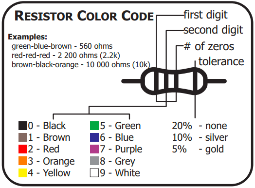
通过颜色代码识别电阻器
图形以上对于“资源管理器”指南非常有用-大多数CIRC都在使用它们。电阻具有不同的值,如果以后卡住,请查阅此图。如果您想快速识别电阻真的好,请玩我们的有趣的iOS游戏:Mho‘s Resistance
引线夹
该套件中的某些组件带有很多长导线。为了使它们与面包板更兼容,可以进行一些更改。
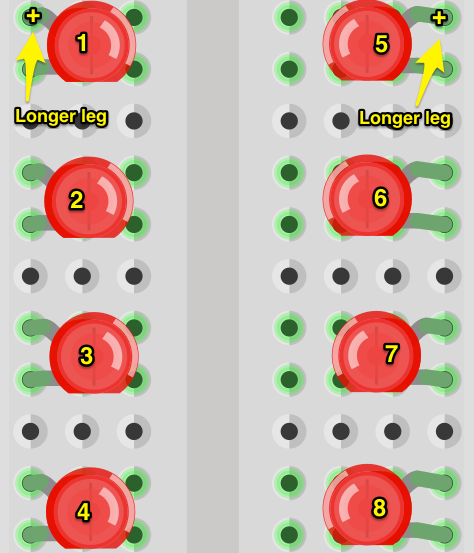
LED:
夹住引线,使长引线约为10mm(3长度为/8英寸),而短的则为〜7毫米(9/32英寸)。如果您不拥有推剪,则可以在Adafruit商店拿起CHP17齐平斜嘴剪
电阻:
将引线弯曲以便与圆柱体成90度角。您可以通过用钳子将其弯曲到90度的桌面角落来精确地做到这一点。
然后将它们剪断,使其长约6mm(1/4“)。
其他组件:
其他组件可能需要裁剪。
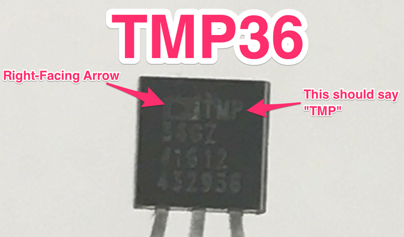
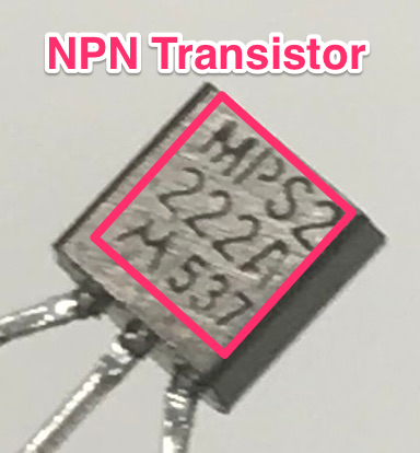
:TMP36和NPN
虽然TMP36模拟温度传感器和NPN晶体管相似,但它们执行的任务却截然不同。为了避免在电路中混淆它们,请使用这两张图片来确定您拥有的部分:
零件字段指南
(所有这些部分都可以在Metro Experimenterskit中找到,单击将图像放大)
零件图片名称和用途?如何识别线索要寻找的内容
LED :当小电流通过时发光。通过它。 (仅在一个方向上)看起来像一个迷你灯泡。2(再长一点,这个连接到正)只能在一个方向上工作。
需要一个限流电阻器
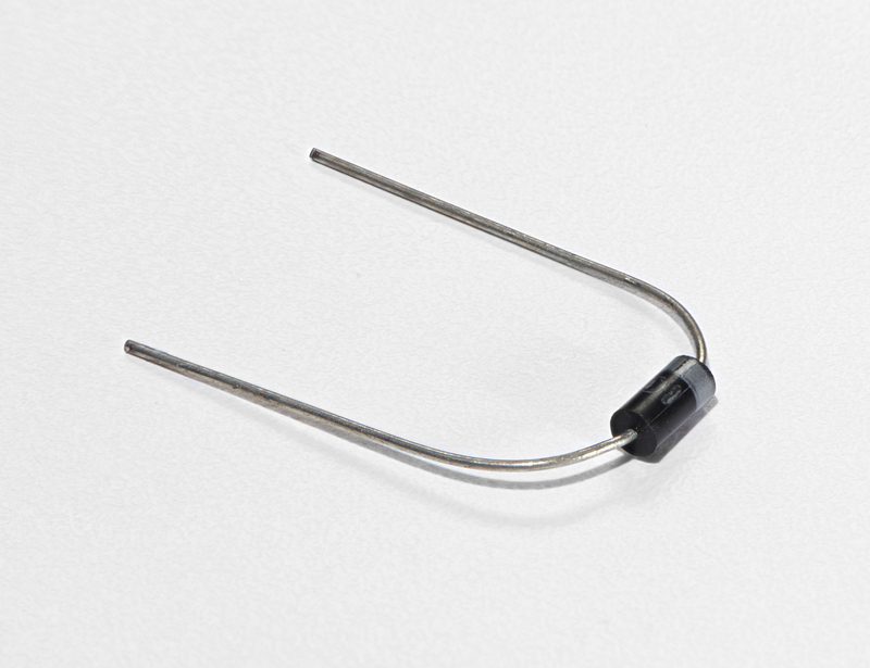
二极管:电子等效于单向阀。允许电流在一个方向上流动,而不能在另一个方向上流动。通常是一个圆柱体,其导线从两端伸出。 (以及指示极性的偏心线)2仅在一个方向上起作用(如果结束,电流将流过
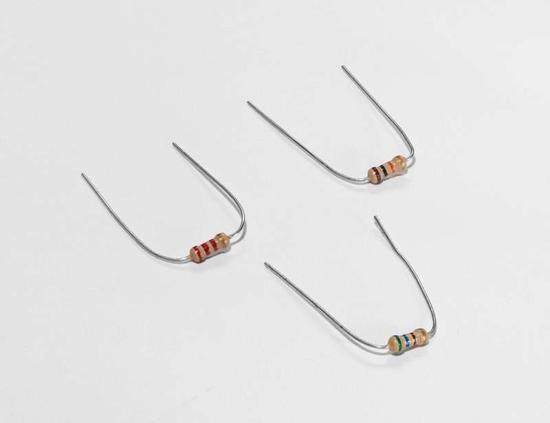
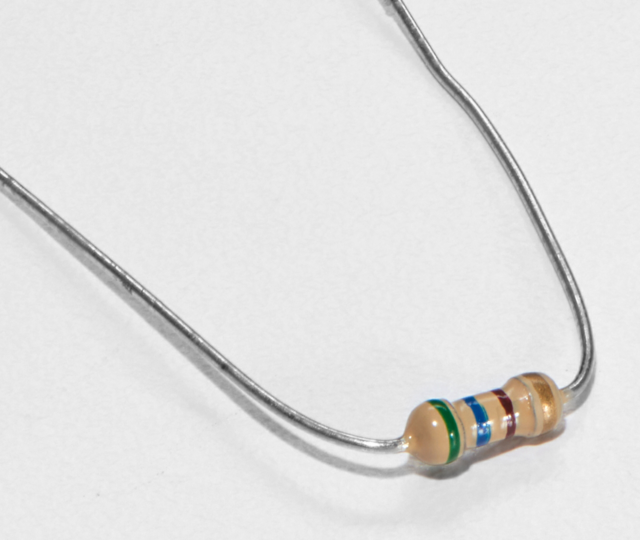
电阻::限制可流经电路的电流量。圆柱体,其中任一根导线均伸出结束。使用颜色编码系统显示该值(有关详细信息,请参见“识别电阻器”部分)2简单捕获错误的值(使用前仔细检查颜色)
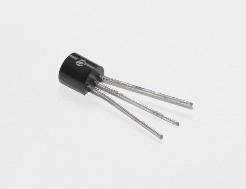
晶体管:使用小电流来切换或放大更大的电流。有许多不同的包装,但您可以从包装中读取零件号(此套件中为P2N2222AG)并在线查找数据表。3(基础,收集器,发射极)正确插拔(通常在基极引脚上也需要一个限流电阻)
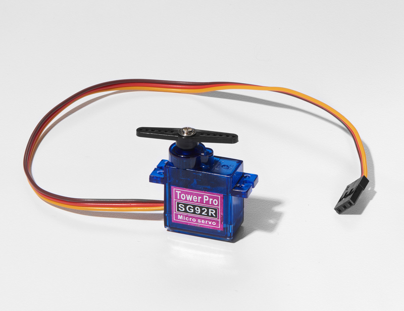
Servo:获取定时脉冲并将其转换一个带有3根导线的塑料盒从一侧伸出,一个带有塑料角的轴从顶部伸出。3插头未极化,因此请确保插头插入正确。
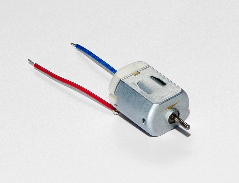
直流电动机:在电流通过时旋转。 p》这很简单,它看起来像马达。通常是带有一端伸出轴的圆柱体。2使用额定值为
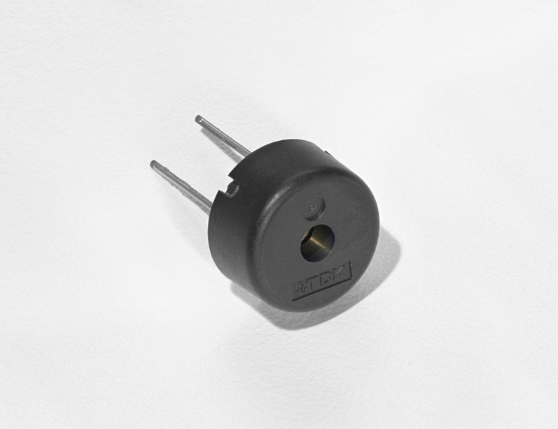
压电式:电流脉冲会使其产生喀哒声。脉冲流会使其发出声音。在此工具包中,它装在一个黑色小桶中,但有时它们只是一个金盘。2难于滥用。
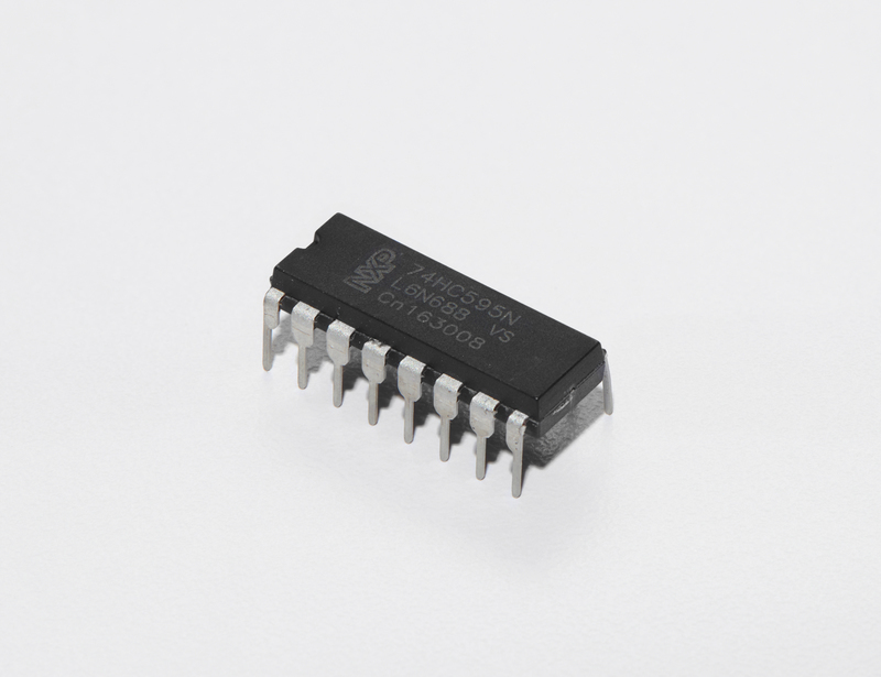
集成电路(IC/“芯片”):可封装任意范围零件ID写在包装的外部(有时需要用灯或放大镜才能读取)p》2至100(此套件具有3根导线的TMP36和16根导线的74HC595)。正确的方向(检查标记,通常是引脚1上方的半月形。)
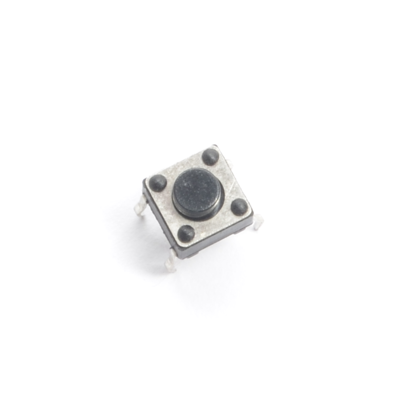
按钮:在按下时完成电路。一点方形,底部引出,顶部有一个按钮。4这些都是almo stt,以便可以将它们插入90度角。
电位计:根据轴的角位置产生可变电阻。它们可以包装成许多不同的形状,寻找刻度盘以识别该零件。3偶然购买对数
光传感器:产生取决于入射光量的可变电阻。通常是一个带有透明顶部和顶部的小圆盘。2请记住,在提供有用的输入之前,它必须位于分压器中。
p》
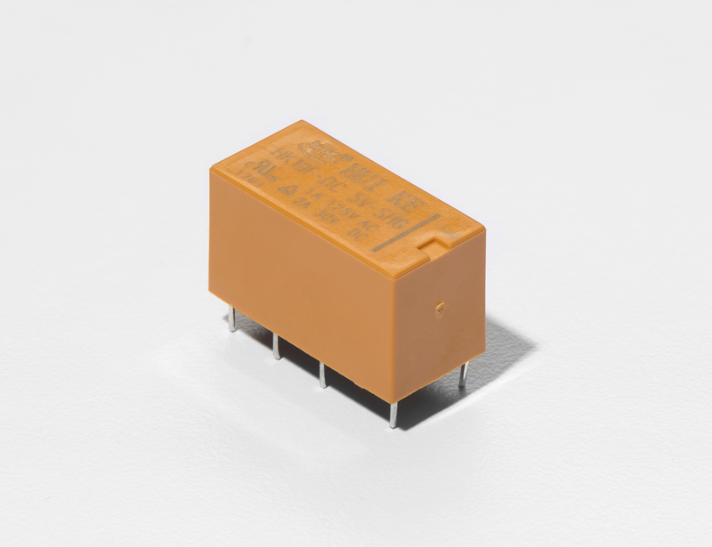
继电器:一个电控开关。高矩形,下方带有引脚。尺寸范围从小到非常大(有些继电器甚至可以控制火车轨道!)5到8(汽车继电器通常有5针,此套件中的继电器有8针)正确的方向。检查继电器上的标记,通常是前两个插针上方的小矩形。继电器的底部有时会带有标记,指示线圈的位置。
根据红外光量产生可变电阻。通常是一个带有凹凸的小矩形。3请确保不要将其向后放置。
 当有小电流通过时发出红外光。 (仅在一个方向上)就像一个小灯泡。2仅在一个方向上起作用。
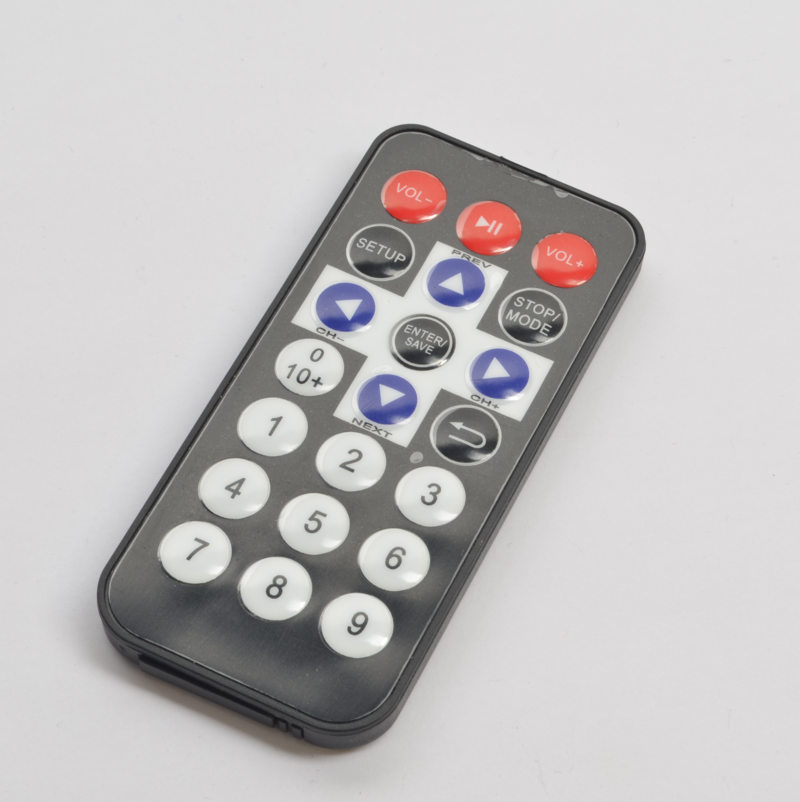
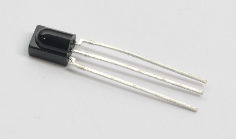
按照NEC红外传输协议发出红外光脉冲。就像电视遥控器。0难以滥用。
关于Arduino编程
使用C语言编程的Adafruit Metrois。这是一个快速的入门教程,面向有一点编程经验并且只需要简要介绍C和Arduino IDE的特性的人。如果您发现这些概念有些令人生畏,请放心,您可以开始遍历电路,并逐步了解其中的大部分内容。
有关此处讨论的主题的更深入说明并用该语言查看“ Arduino.cc参考”页面。
Arduino IDE
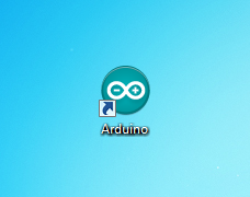
现在已经安装并配置了Arduino,下面我们来看看。双击Arduino图标将其打开。它将在称为 IDE 的工作空间中打开:
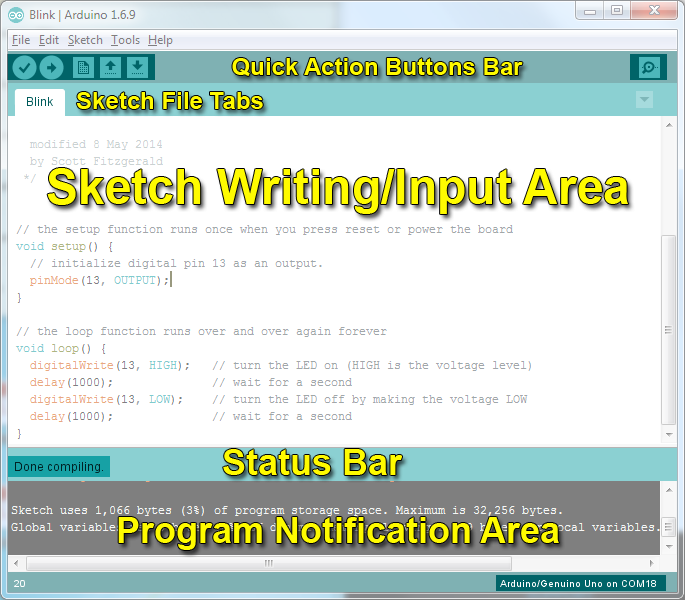
不要感到不知所措-随着《实验者指南》的进展,您将学习使用IDE的各个部分。
结构
您可以想到Arduino项目的结构,例如建筑物的脚手架。必须遵循特定的结构,否则所有结构都将崩溃(并且无法编译)。
void setup() { }
两个大括号之间的所有代码 { } 仅在Metro程序第一次运行时运行。
下载:file
复制代码
void setup() {
// put your setup code here, to run once
} void setup() {
// put your setup code here, to run once
}
void loop() { }
此功能在 void setup()具有完成。它运行一次后,它将一次又一次地永远运行,直到断电为止。
下载:文件
复制代码
void loop() {
// put your main code here, to run repeatedly
} void loop() {
// put your main code here, to run repeatedly
}
语法
其中一个稍微 令人沮丧 C的元素是其格式要求或语法。虽然令人沮丧,但这也使该语言非常强大。如果您还记得以下内容,则应该没事:
// (单行注释)
在编写新草图或查看旧草图时,对标出您的想法很重要。为此,请输入两个正斜杠,直到行尾的所有内容都将被程序忽略。
下载:文件
复制代码
// this is a comment, it won’t get run by the compiller
this is not a comment, it will cause an error when run!! // this is a comment, it won‘t get run by the compiller
this is not a comment, it will cause an error when run!!
/* */ (多行注释)
如果您有很多话要说,您可以使用多行注释在多行上键入。这两个符号之间的所有内容都将在程序中被忽略,就像单行注释一样。
下载:文件
复制代码
/*
* Oh, hey!
* hi there!
*/ /*
* Oh, hey!
* hi there!
*/
{ } (卷曲括号)
这些用于标记代码块的开始和结束时间。您会看到它在函数和循环中使用。
下载:文件
复制代码
void serialPrintHello ()
{ // code begins
Serial.println(“Hello”);
} // code ends void serialPrintHello ()
{ // code begins
Serial.println(“Hello”);
} // code ends
; (分号)
每行代码必须必须结束用分号。缺少分号将导致您的代码拒绝编译。往往很难找到它们,将它们视为代码的隐藏并寻求拥护者,而且很难忽略它们并导致错误。
下载:文件
复制代码
// this will compile
int servoPin = 5;
// this won’t compile, it‘s missing a semicolon
int servoPin = 5 // this will compile
int servoPin = 5;
// this won’t compile, it‘s missing a semicolon
int servoPin = 5
变量
无非就是以智能方式移动数字的指令。变量用于移动。
int (整数)
主要功能。该整数以 2字节(或16位)的形式存储数字。它没有小数位,将存储在-32,768和32,767之间的值。
下载:文件
复制代码
// this makes the variable i store the value 2
int i = 2; // this makes the variable i store the value 2
int i = 2;
long
当整数不够大时使用long。占用 4字节(32位)RAM,并且其范围比整数大:-2,147,483,648和2,147,483,647之间。
下载:文件
复制代码
// this makes the variable j store the value 2000083647
j = 2000083647 // this makes the variable j store the value 2000083647
j = 2000083647
bool (布尔值)
布尔值是一个简单的变量,可以为True或False。真对应于位“ 1”,假对应于位“ 0”,它仅是一位。
下载:文件
复制代码
// let’s make a boolean called openSource and
// set it to True
bool openSource = True;
// now let‘s make a variable called closedSource and
// set it to False
bool closeDSource = False; // let’s make a boolean called openSource and
// set it to True
bool openSource = True;
// now let‘s make a variable called closedSource and
// set it to False
bool closeDSource = False;
float
用于浮点运算,例如小数。 Pi是一个超长十进制数3.1415 。。.,但可以将其表示为浮点数,以使其具有更高的精度(3.14比仅3精度更高)。它占用4个字节(32位)的RAM,范围在-3.4028235E + 38和3.4028235E + 38之间。
下载:文件
复制代码
// integers can’t store decimal points
int pi = 3;
// so we use a float!
float pi = 3.14; // integers can‘t store decimal points
int pi = 3;
// so we use a float!
float pi = 3.14;
char (字符)
存储一个字符,使用ASCII码(即“ A” = 65)。使用一个字节(8位)的RAM。 Metrohandles字符串是char数组。
下载:文件
复制代码
// mychar stores the letter A, represented by an ascii value of 65
char myChar = ’A‘; // mychar stores the letter A, represented by an ascii value of 65
char myChar = ’A‘;
数学
现在我们可以将数字存储在变量中了,我们将要对其进行操作:
=(等于)
使某些东西与其他东西相等。
下载:文件
复制代码
// b equals one
int b = 1;
// now, the value stored in b equals b times 2, which is one
b = b * 2; // b equals one
int b = 1;
// now, the value stored in b equals b times 2, which is one
b = b * 2;
%(模)
给出除法运算的其余部分。
下载:文件
复制代码
// 12 divided by 10 = 1.2, modulo (%) will give us the remainder only
int mod = 12%10
// the value stored in int mod now equals 2 // 12 divided by 10 = 1.2, modulo (%) will give us the remainder only
int mod = 12%10
// the value stored in int mod now equals 2
+(加法)
将两个数字加在一起。
下载:文件
复制代码
int i = 2+2
// the value stored in int i now equals 4 int i = 2+2
// the value stored in int i now equals 4
-(减法)
从另一个数字中减去一个数字。
下载:文件
复制代码
int f = 4-2
// the value stored in int f now equals 2 int f = 4-2
// the value stored in int f now equals 2
*(乘法)
将两个数字相乘。
下载:文件
复制代码
int z = 5*2
// the value stored in int z now equals 10 int z = 5*2
// the value stored in int z now equals 10
/(部门)
划分两个数字。
下载:文件
复制代码
int y = 10/2
// the value stored in int y now equals 5 int y = 10/2
// the value stored in int y now equals 5
控制流程
程序能够控制执行流程(下一步运行)。这些是您应该熟悉的几个基本元素:
If 条件
如果条件为真,则将在花括号之间执行代码如果条件也为假,它将测试else条件,否则将执行else代码。
下载:file
复制代码
int i = 0;
if(i 》 5) {
// this code does not execute, i is not greater than 5
}
else if (i 》 2) {
// this code also does not execute, i is not greater than 2
}
else {
// this code DOES execute, i is none of the above, so it falls into
// this category
} int i = 0;
if(i 》 5) {
// this code does not execute, i is not greater than 5
}
else if (i 》 2) {
// this code also does not execute, i is not greater than 2
}
else {
// this code DOES execute, i is none of the above, so it falls into
// this category
}
for() 循环
在您要重复一段代码多次(可以递增i ++或递减i--或使用任何变量)。
下载:file
复制代码
for (int i = 1; i 《 5; i++) {
// this code will run 4 times
} for (int i = 1; i 《 5; i++) {
// this code will run 4 times
}
数字输入/输出
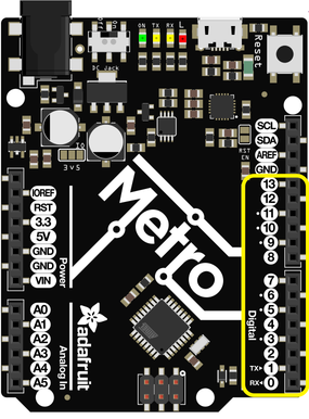
Metro(或Metro Express)的右侧有一个标头,其中包含13个数字引脚。这些引脚可以设置为0到1023之间的数字值。以下命令仅与这些引脚有关:
pinMode(pin, mode)
用于设置引脚的模式。
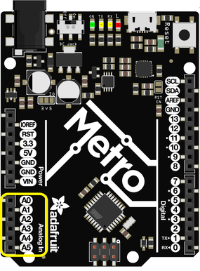
Pin是您要寻址的PIN码,数字0-19。您还可以在模拟引脚0-5上设置数字pinMode。 0-5的映射为14-19。
模式可以设置为 INPUT 或 OUTPUT
下载:文件
复制代码
// a red LED is connected on Pin #11
int redLedPin = 11;
void setup()
{
// set the red LED as an OUTPUT
pinMode(redLedPin, OUTPUT);
} // a red LED is connected on Pin #11
int redLedPin = 11;
void setup()
{
// set the red LED as an OUTPUT
pinMode(redLedPin, OUTPUT);
}
digitalWrite(pin, value)
如果使用pinMode将引脚设置为 OUTPUT ,则可以将其设置为 HIGH或低电平。将引脚设置为高会将其上拉至+ 3.3V或+ 5V。将其设置为低将使其接地,或为零伏。
下载:file
复制代码
// this code will flash the LED on and off forever
void loop()
{
// set the pin high to turn ON the LED
digitalWrite(redLedPin, HIGH);
delay(500);
// set the pin low to turn OFF the LED
digitalWrite(redLedPin, LOW);
delay(500);
} // this code will flash the LED on and off forever
void loop()
{
// set the pin high to turn ON the LED
digitalWrite(redLedPin, HIGH);
delay(500);
// set the pin low to turn OFF the LED
digitalWrite(redLedPin, LOW);
delay(500);
}
digitalRead(pin)
将图钉设置为输入后,您可以使用它返回高(拉至+5伏)还是低(拉至地面)。
下载:文件
复制代码
// this will store the value of sensorPin in an integer called sensorValue
int sensorValue = digitalRead(sensorPin); // this will store the value of sensorPin in an integer called sensorValue
int sensorValue = digitalRead(sensorPin);
模拟输入/输出
尽管Metro是数字板,但它能够做模拟操作。这对于获取精确的传感器值很有用。 以下是处理非数字化内容的方法:
analogWrite(pin, value)
在“引擎盖”的技巧,Metro能够通过脉冲宽度调制写入模拟值。您可以写入0到255之间的任何值。
下载:文件
复制代码
void loop()
{
// set the LED to full brightness
analogWrite(ledPin, 255);
// turn the LED off
analogWrite(ledPin, 0);
} void loop()
{
// set the LED to full brightness
analogWrite(ledPin, 255);
// turn the LED off
analogWrite(ledPin, 0);
}
analogRead(pin)
读取模拟引脚的值。返回的值可以在0到1024之间。
下载:文件
复制代码
sensorVal = analogRead(sensorPin); sensorVal = analogRead(sensorPin);
下载
实验者指南提供了可用的源代码和面包板图,可在我们的GitHub上免费下载:
贴图

我们使用开源工具Fritzing设计了您在本指南中看到的面包板布局图。如果要查看或修改这些模板中的任何一个,请单击下面的按钮:
注意:大多数图都包含用于Fritzing的组件从Adafruit Fritzing零件/板库中获得。您需要下载并安装此订单才能编辑图表。
实验者指南的面包板装饰图
代码
Metro Explorers Guide Code
存储在github Githubrepository中的所有本指南代码的最新版本。随时向该存储库提交问题,贡献,请求和修改,我们将回答您在社区支持论坛中遇到的任何问题。
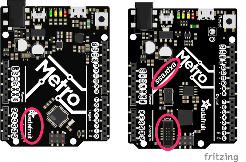
我拥有什么板?
本指南旨在与Metro和Metro Express一起使用。判断您的木板是否是快递的主要方法是在木板上说“表达”。 Metro Express的底部还有一个SWD端口,该端口不在Metro上。下图指出了这两个区别:
我有地铁
此指南将在不做任何修改的情况下正常工作,请按照常规步骤进行操作,并玩得开心!
我有Metro Express
在阅读本指南时,有两件事需要注意:
1)接线:有些电路有一个额外的接线页面,称为“ Metro Express接线”,有些则没有。如果您要查找的电路没有此子页面,请使用常规的Metro接线。如果您看到“ Metro Express接线”页面,请使用该页面中的接线代替。
2)代码:如果需要对以下内容进行修改Metro Express的代码,将显示将代码切换为Metro Express兼容代码的说明。
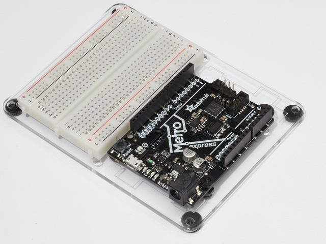
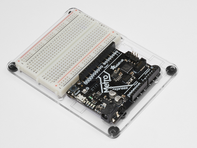
设置Metro
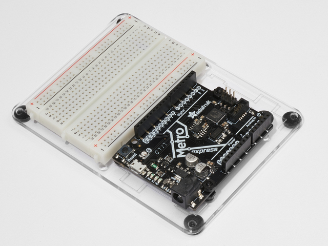
MetroX Classic/Express Kit用户:您设置了吗?
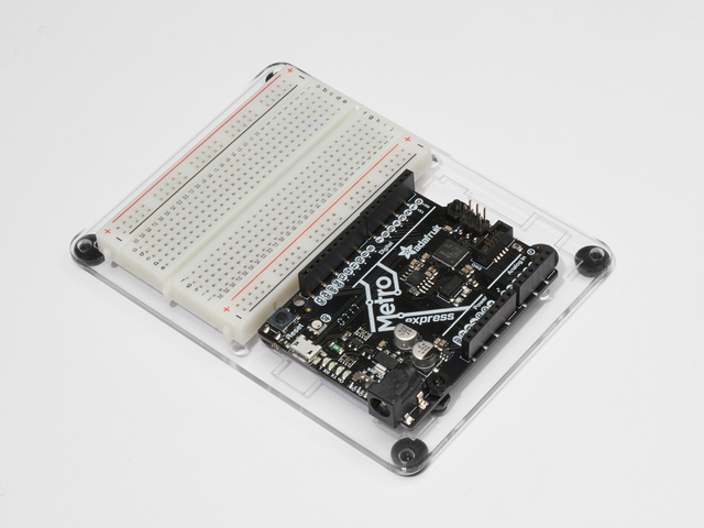
如果尚未组装Metro或Metro Express,半尺寸面包板和安装板,请单击此处获取说明
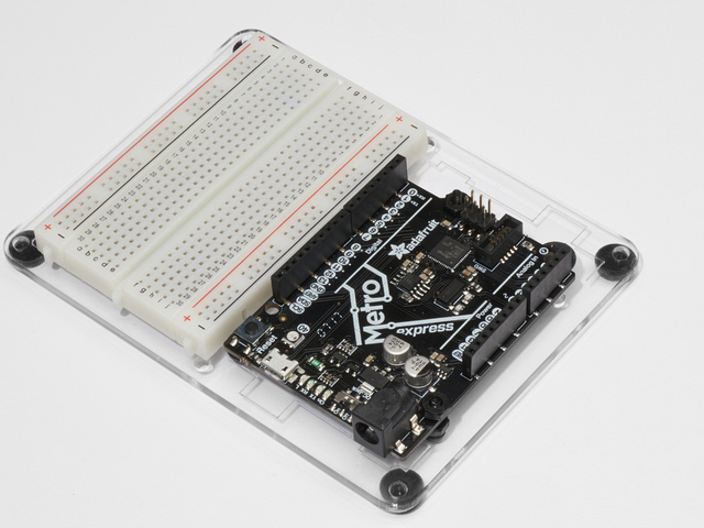
您需要一个Adafruit Metroor Metro Express。
如果您没有购买Metro实验者工具包,则可能要购买一块半尺寸的面包板和用于面包板的塑料安装板。
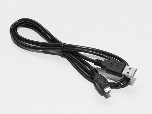
USB Mi cro电缆
我对此压力还不够。 确保您的USB电缆连接良好。顽皮的USB电缆会真的毁了您的一天,就像鞋子上的石头一样。扔掉不良的电缆,并用优质的电缆代替它们-它们的用途是一次性的!
许多人有问题,因为他们选择了“仅充电”的USB电缆,而不是“数据/同步”的电缆。绝对确保您拥有高质量的同步电缆。如果遇到问题,很可能会使用仅可充电的电缆。
为Metro供电!
如果您有Metro,那么接下来的这些步骤将使您在Arduino环境中进行设置。如果不确定所用的板子,请单击此处。
将USB Micro电缆连接到Metro的USB端口。 打开 LED应变为稳定的绿色,并保持点亮状态。
Arduino Bootloader检查。
接下来,您要检查Metro是否使用Arduino编程引导加载程序,这是使用所必需的。
插入电源(确保打开 LED指示灯已打开)时,迅速按一下“重置” 按钮。您会看到它快速闪烁 3 次。它的发生速度非常快,因此请不要担心是否看不到所有三个闪烁。
下载Arduino软件
这是免费应用程序,您将使用该应用程序编写程序并进行交谈到您的地铁。以下是大多数操作系统上的安装说明(以及运行CodeBender的Chromebook用户的浏览器!)。
转到官方Arduino软件页面
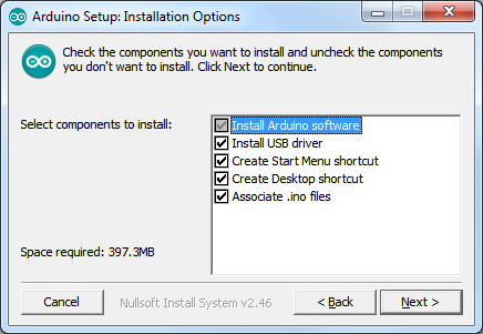
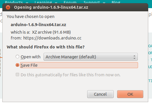
点击单击上面的按钮转到官方软件页面(https://www.arduino.cc/zh/Main/Software),您会看到一个类似以下的框:
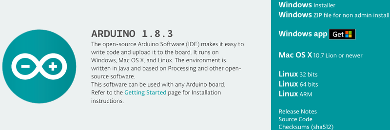
上面的图片显示的是Arduino 1.8.3,但我看到了另一个版本。
别担心,Arduino软件在下常量修订版,并且上面的屏幕截图不代表最新版本。下载适合您平台的版本。
Windows设置
适用于Windows的下载
使用 Windows Installer下载并安装。 .zip文件(非管理员安装)是不 推荐。
(Windows)安装Arduino
单击 Windows Installer 链接到下载安装程序,然后双击以启动它。
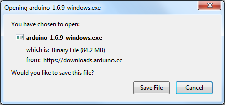
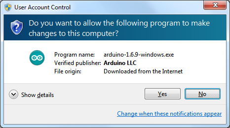
您可能会收到警告,询问您是否确定要运行安装程序。可以,单击是
有一个开源许可证可以单击。在默认位置安装
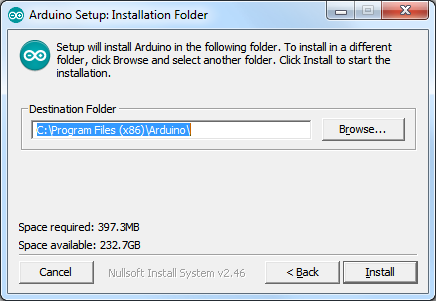
您可以使用默认设置安装选项
最后,将需要一两分钟来安装
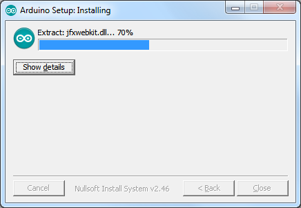
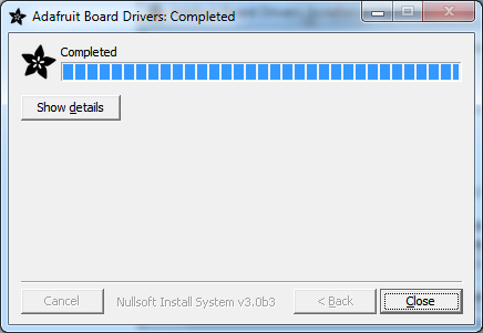
完成后,您将安装软件:
(Windows )安装驱动程序
根据您的Arduino兼容,您可能需要为USB到串行转换器安装单独的驱动程序
对于所有Adafruit兼容产品,我们都有多合一安装程序,它将安装所有Adafruit板驱动程序。它还将安装FTDI和CP210x驱动程序
点击下面下载我们的驱动程序安装程序:
下载Adafruit Boards Windows驱动程序安装程序
下载并运行安装程序
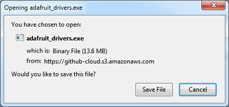
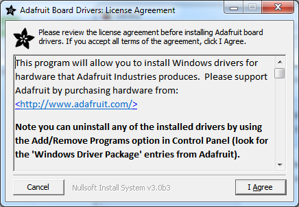
运行安装程序!由于我们也捆绑了SiLabs和FTDI驱动程序,因此您需要单击许可证
选择要安装的驱动程序(建议选择所有这些,这样您就不必在开始探索其他Arduino兼容产品时就不必担心安装驱动程序了。
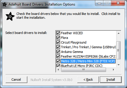
点击安装进行安装’
您不需要重新启动计算机,但这不是坏的主意!/p》
(Windows)查找您的串行COM端口
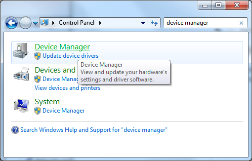
要验证您的Arduino驱动程序是否正确安装,请将其插入USB并打开设备管理器。您可以在控制面板(搜索设备管理器)中找到设备管理器
打开设备管理器时,找到名为 Ports 的部分并将其展开:
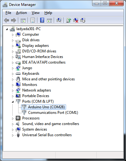
您会在一些显示的文本旁边看到一个图标》 Arduino UNO(COMxx),其中 xx 是数字
如果您有Metro,它不会说Arduino UNO,而只是说 USB串行端口(COMxx)
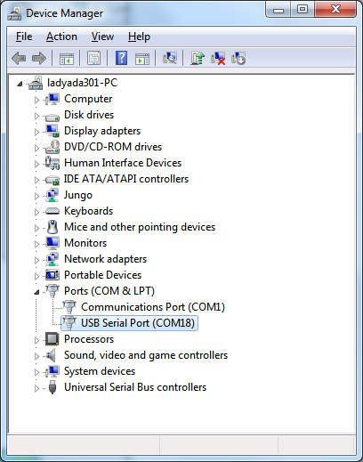
COM号可能会有所不同,但应该类似于 COM3 或 COM4 。 COM代表“通信”,每个都有一个唯一的编号,称为COM端口号。在这种情况下,COM端口号为COM18。
您可以拔下Arduino,以查看COM端口设备消失并在插入时重新出现。
如果您 don ‘t 看到Arduino出现,请检查:
您的电缆是数据电缆还是仅可充电?尝试使用另一条USB电缆
尝试使用另一条USB端口!
验证是否已安装驱动程序,您随时可以尝试再次安装它们(从不伤人)
检查Arduino不需要其他驱动程序,您的供应商可以在必要时为您提供正确的驱动程序
Mac设置
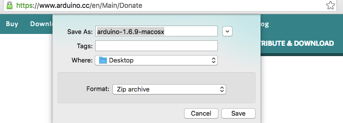
下载macOS或OS X
下载Mac OS X的版本,解压缩.zip文件,然后将“应用程序”拖出文件夹。
(macOS/OS X)安装Arduino
点击 Mac OS X安装程序链接以下载安装程序
然后双击以展开/启动它
它将自动为您提供 Arduino应用蓝绿色图标:
(macOS/OS X)找到您的串行端口
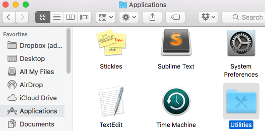
现在,我们要确保您的Metro与计算机正确通信。在您的应用程序文件夹中,找到实用程序文件夹,然后双击它。
然后,找到名为“终端” 的应用程序。双击以打开它:
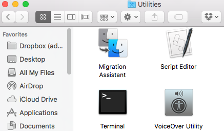
终端打开后,系统会提示您。在其中键入以下内容:
ls /dev/cu*
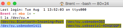
键入后,您应该会看到一行包含文本 /dev/cu.usbmodemxxxx OR /dev/cu.usbserial-xxxxx 。 xxxx的可以是任何字母或数字。如果看到此消息,则说明驱动程序已正确安装,并且在计算机上已找到Metro。
如果您不习惯使用Terminal,则还有另一种(更简便的)方法检查所有东西是否都已正确安装。点击菜单栏上的苹果图标。在下拉菜单中,单击关于本机。
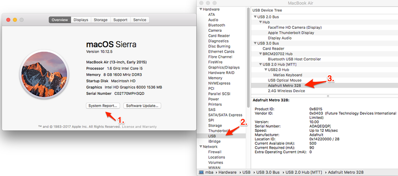
然后,单击系统报告。 System Profiler将打开,然后在硬件下拉菜单中单击 USB 。您应该将Adafruit Metro 328视为USB设备之一。
(macOS/OS X)安装驱动程序
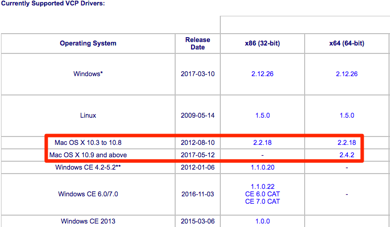
下一步,您将要获取并安装FTDI VCP驱动程序和SiLabs CP210x驱动程序。
首先,导航至FTDI VCP站点并获取适用于您的OS X版本和平台的驱动程序。
然后解压缩文件并安装.dmg文件。
您还将需要SiLabs CP210x驱动程序。您可以从SiLabs网站获得它们。
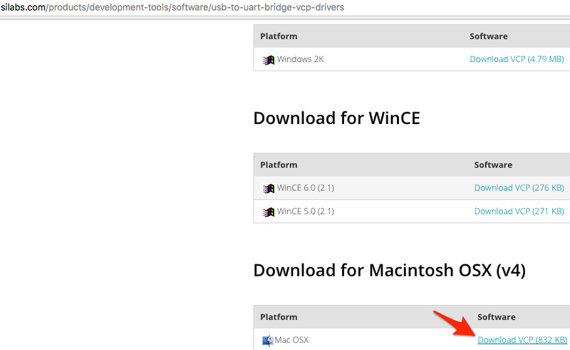
然后解压缩文件并安装.dmg文件。
验证macOS/OS XDrivers
我们只想验证所有设置是否正确。插入Metro Classic,然后打开Arduino IDE并导航到工具》端口。
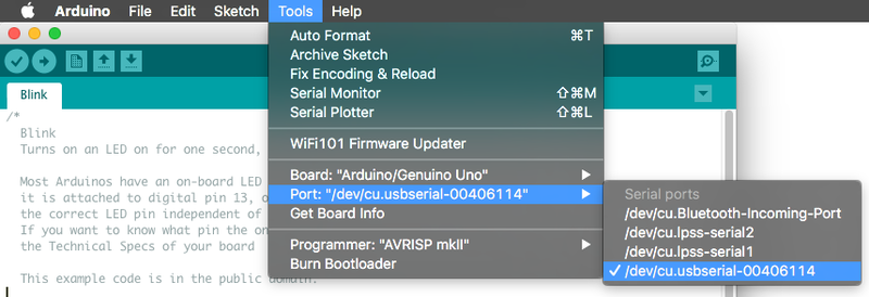
您应该看到一个列为/dev/cu.usbserial 的设备,其后是数字和/或字母。这是您的Metro Classic。
如果看不到此内容,请确保正确安装了FTDI和SILabs驱动程序(适用于正确的OS版本和平台)。然后,检查您正在使用的USB端口(尝试另一个端口)或电缆(您可能正在使用仅充电电缆)。
Linux设置
Linux版下载
32位和64位Linux都有下载选项。下载所用系统的版本,手动解压缩.tar文件,然后安装软件。
(Linux)安装Arduino
单击匹配的 Linux Installer 链接(32位,64位或ARM)下载安装程序-将文件保存到“下载”文件夹中
从终端程序中, cd 到下载目录,然后用 tar xf arduino * .xz 解压缩该软件包,然后 cd 进入创建的 arduino-nnn 文件夹:
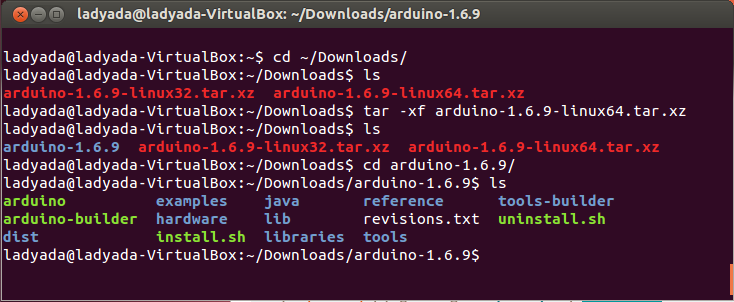
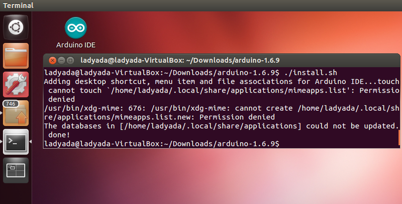
运行 。/install.sh 以安装软件。我安装了旧的Ubuntu,因此收到警告,但确实为我创建了该桌面图标!
(Linux)安装驱动程序
Linux不会”假设您运行的是v2.6或更高版本的内核,则无需安装任何驱动程序,这几乎可以肯定。这些说明假定您正在运行Ubuntu。每个Linux发行版都不同,但是其他发行版的说明应该足够基本。
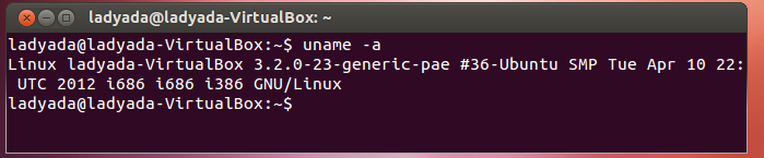
您可以通过在终端窗口中运行 uname -a 来验证内核版本,请注意该内核是版本 2.6.20
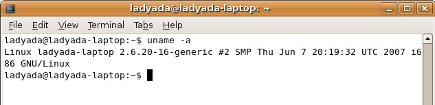
,而该内核是 3.2.0-23
一些较旧的Linux发行版用于安装 brltty (盲文设备),这会与Arduino发生冲突。 如果已安装Brltty,则必须将其卸载!请通过在终端窗口中运行sudo apt-get remove brltty 或同等功能来卸载。如果它说没有安装,那就可以了。如果您没有运行Debian衍生的安装程序,请使用必要的工具来验证您是否没有 brltty 运行
(Linux)在Arduino中找到您的串行端口
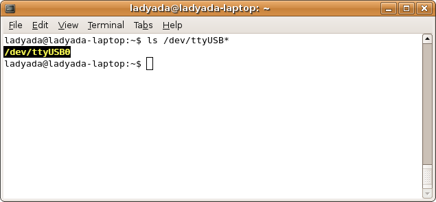
,确认绿色LED点亮,然后在终端窗口中输入 ls/dev/ttyUSB * ,您应该会看到一个名为ttyUSB0的设备文件
如果您似乎找不到它,请使用 dmesg |在插入Arduino之后立即查找尾部,并寻找有关将设备文件放置在何处的提示。例如,这里说串行设备转换器现在已连接到ttyUSB0
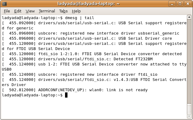
如果您看到类似这样的内容
[ 1900.712000] ftdi_sio 2-10:1.0: FTDI USB Serial Device converter detected
[ 1900.712000] drivers/usb/serial/ftdi_sio.c: Detected FT232BM
[ 1900.712000] usb 2-10: FTDI USB Serial Device converter now attached to ttyUSB0
[ 1901.868000] usb 2-10: usbfs: interface 0 claimed by ftdi_sio while ’brltty‘ sets config #1
[ 1901.872000] ftdi_sio ttyUSB0: FTDI USB Serial Device converter now disconnected from ttyUSB0
[ 1901.872000] ftdi_sio 2-10:1.0: device disconnected
这意味着您尚未卸载 brltty ,应重试。
为Metro Express配置Arduino
此页面仅适用于Metro EXPRESS用户,如果您使用的是常规Metro,则可以忽略此页面。
如果您已按照“设置Metro Express”页面进行操作,则应该准备好滚。我们需要对Arduino进行一些修改,以使其能够与Metro Express一起使用。
Metro Express Arduino IDE设置
下载并安装最新版本的Arduino IDE 后,您可以将需要启动IDE并导航到首选项菜单。您可以通过 Windows 或 Linux 中的 File 菜单或 OS上的 Arduino 菜单访问它X 。
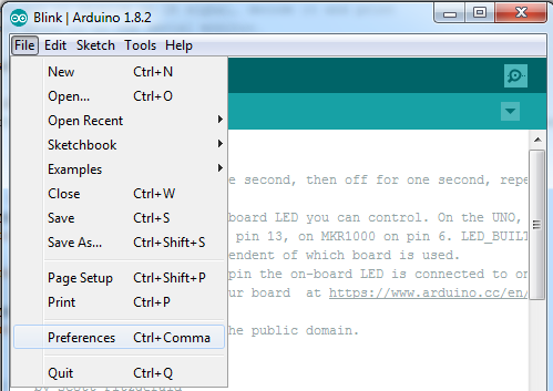
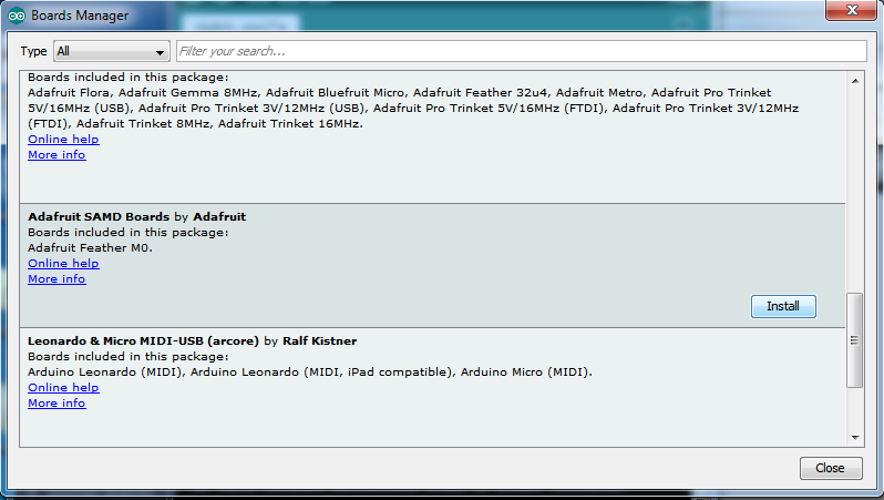
将弹出一个对话框,如下所示。
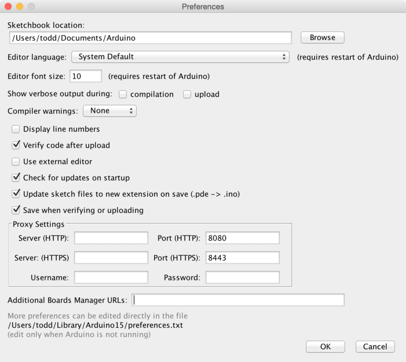
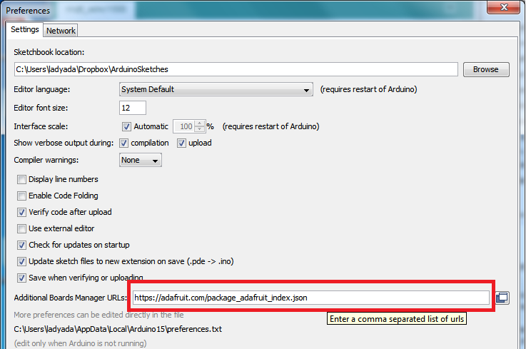
我们将向新的其他董事会管理器URL 选项中添加一个URL。 URL列表以逗号分隔,您只需添加一次每个URL。新的Adafruit开发板和对现有开发板的更新将在每次打开时由开发板管理器自动提取。这些URL指向Board Manager用来建立可用和已安装板列表的索引文件。
要查找可以添加的URL的最新列表,您可以访问第三方板列表Arduino IDE Wiki上的URL。在此示例中,我们只需要向IDE添加一个URL,但是 您可以通过用逗号分隔 来添加多个URL。将下面的链接复制并粘贴到Arduino IDE首选项的 Additional Boards Manager URLs 选项中。
https://adafruit.github.io/arduino-board-index/package_adafruit_index.json
以下是每个Adafruit提供的软件包的简短说明,当您添加URL时,它们将在Board Manager中可用:
Adafruit AVR Boards -包括对Flora,Gemma,Feather 32u4,Trinket和Trinket Pro的支持。
Adafruit SAMD板-包括对Feather M0,Metro M0,Circuit Playground Express的支持,Gemma M0和Trinket M0
Arduino Leonardo和Micro MIDI-USB -使用arcore项目为Flora,Feather 32u4,Micro和Leonardo添加了USB over MIDI支持。/li》
如果要支持多个开发板,例如ESP8266和Adafruit,请在文本框中输入两个URL,并用逗号(,)隔开
完成后,单击确定以保存新的偏好设置。接下来,我们将研究使用Board Manager安装板。
现在继续下一步,实际安装板支持包!
在Arduino IDE中使用Metro Express
自Metro Express开始M0使用运行在48 MHz的ATSAMD21芯片,您可以很容易地使其与Arduino IDE一起使用。大多数库(包括诸如NeoPixels和display之类的流行库)都可以与M0一起使用,尤其是使用i2c或SPI的设备和传感器。
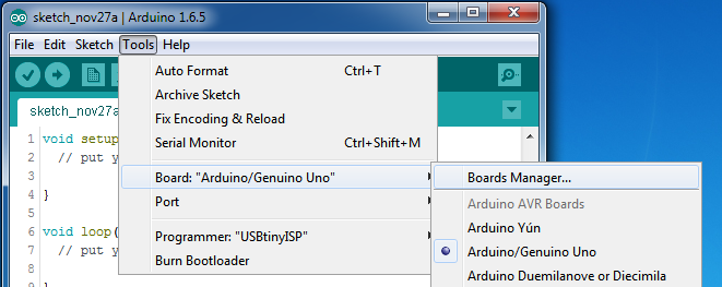
现在,您已经在Arduino IDE首选项中添加了适当的URL。在上一页中,可以通过导航到工具-》委员会菜单来打开委员会管理器。
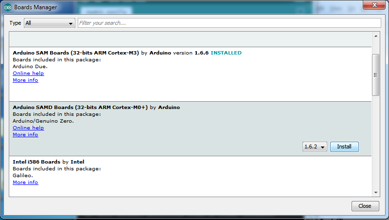
董事会管理器打开后,点击窗口左上角的类别下拉菜单,然后选择已贡献。然后,您将能够选择并安装由添加到首选项中的URL提供的木板。
安装SAMD支持
首先,安装 Arduino SAMD开发板版本 1.6.15 或更高版本
您可以在顶部搜索栏中键入 Arduino SAMD ,然后在看到该条目时,单击安装
安装Adafruit SAMD
接下来,您可以安装Adafruit SAMD软件包以添加板文件定义
您可以键入 Adafruit SAMD ”,然后在看到条目时,单击安装
即使从理论上讲您不会不需要-我建议重新启动IDE
退出并重新打开Arduino IDE ,以确保所有板卡均已正确安装。现在,您应该能够选择并上传到工具-》面板菜单中列出的新面板。
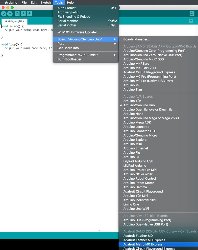
从下拉列表中选择 Adafruit Metro M0 Express 。
CIRC01:LED闪烁
我们在做什么
LED(发光二极管)用于各种聪明的事情,这就是为什么我们将它们包括在本指南中的原因。我们将以一个非常简单的开始,反复打开和关闭,以产生令人愉快的闪烁效果。首先,请从零件页面中获取零件,然后根据布局图插入所有零件。
零件
让我们首先收集我们的部分:
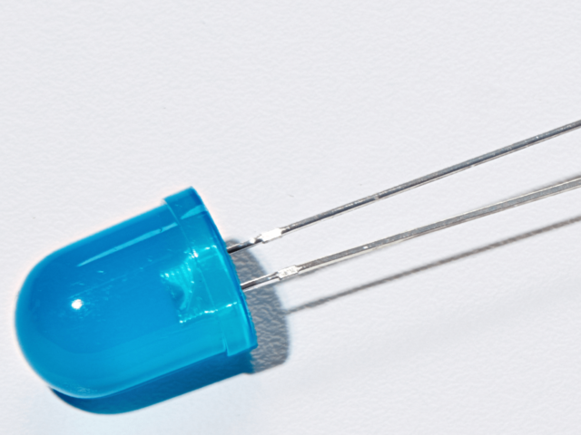
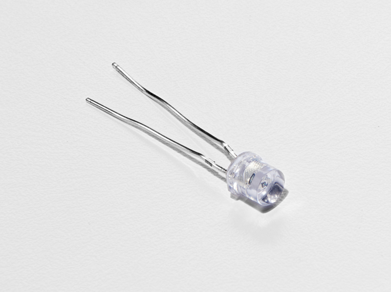
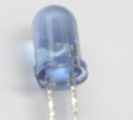
10mm蓝色LED
如果您想从Adafruit商店订购更多这些10mm LED,请单击此处!
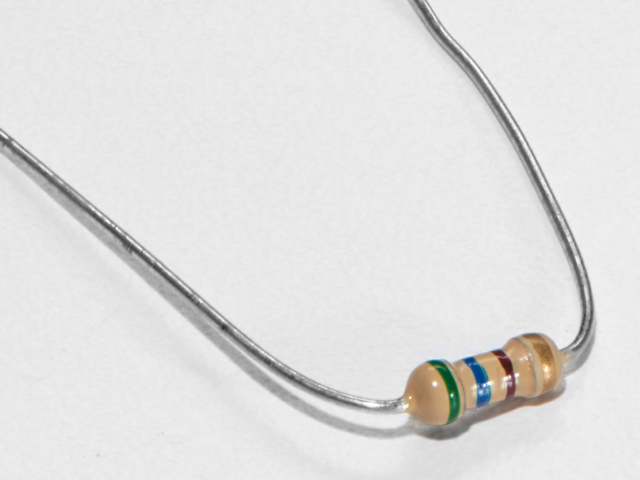
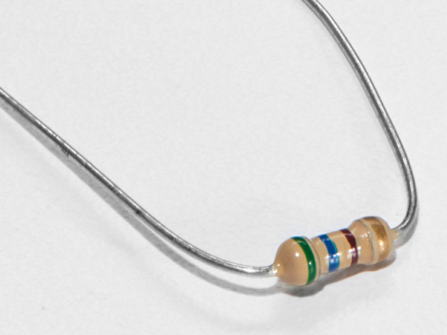
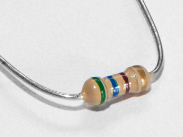
560欧姆电阻
颜色:绿色》蓝色》棕色
如果您想从Adafruit商店订购更多电阻,请单击此处! (它们的电阻为470欧姆,但可以用)
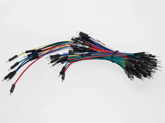
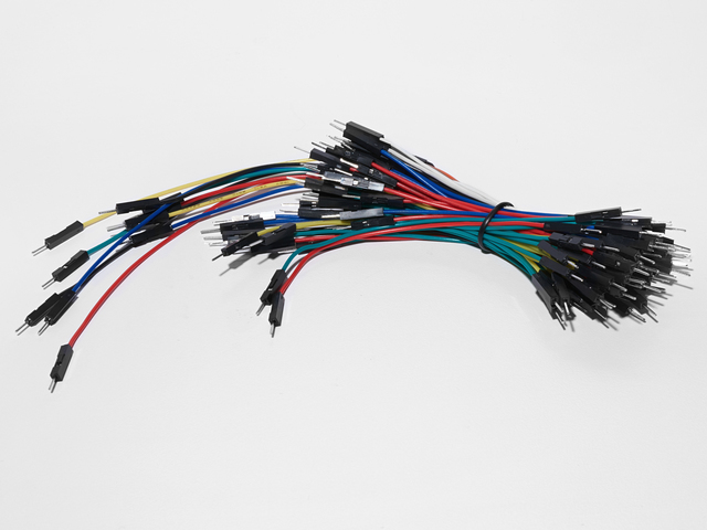
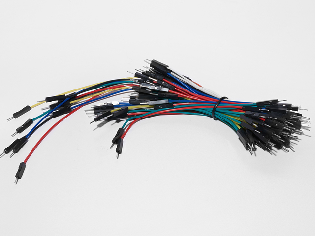
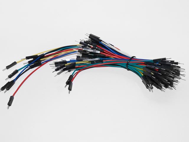
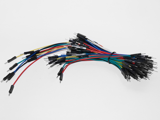
面包板接线束
如果您想从Adafruit商店订购更多电线,请单击此处!
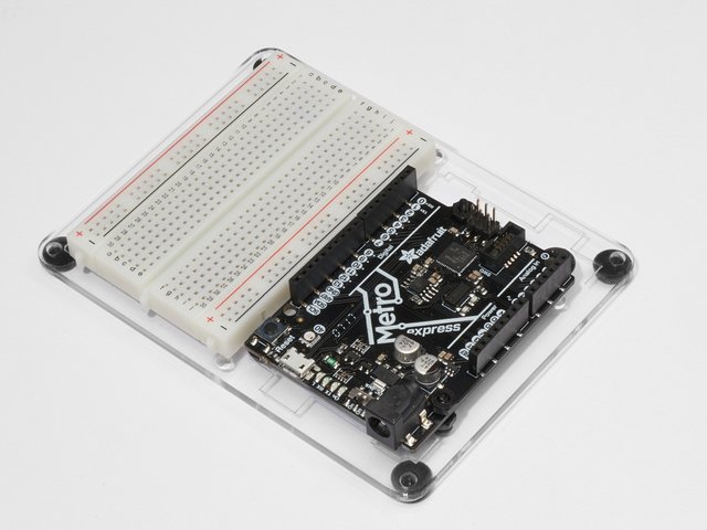
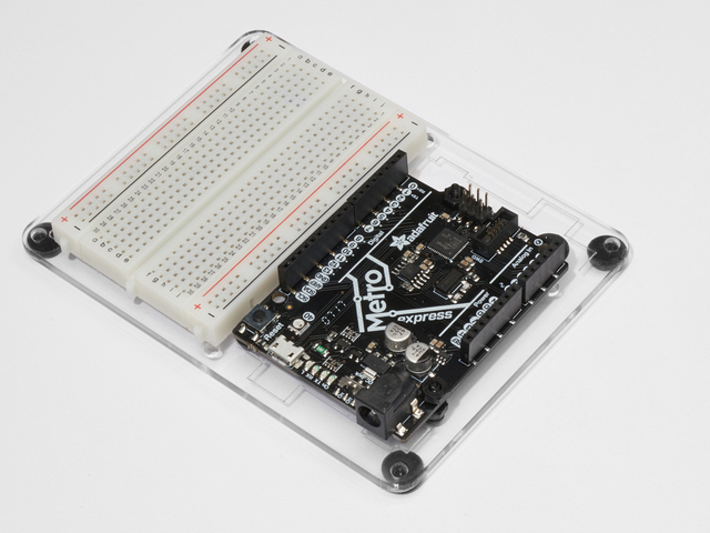
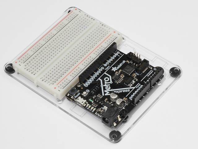
Adafruit Metro(或Metro Express)+面包板+安装板
如果您尚未组装,我们将为您提供方便的指南!
如果d想从Adafruit商店订购额外的塑料安装板,Adafruit Metro,AdafruitMetro Express或Mini-Breadboard,请点击此处!
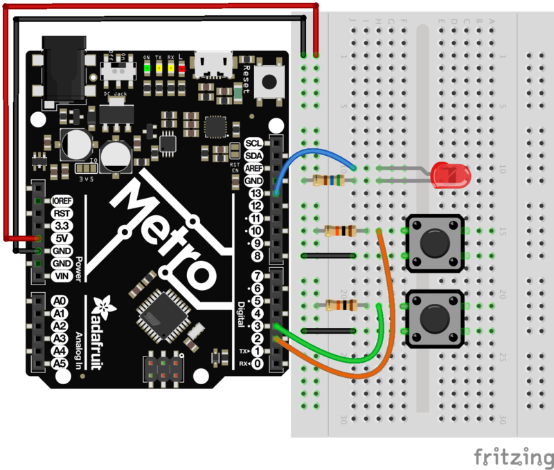
接线
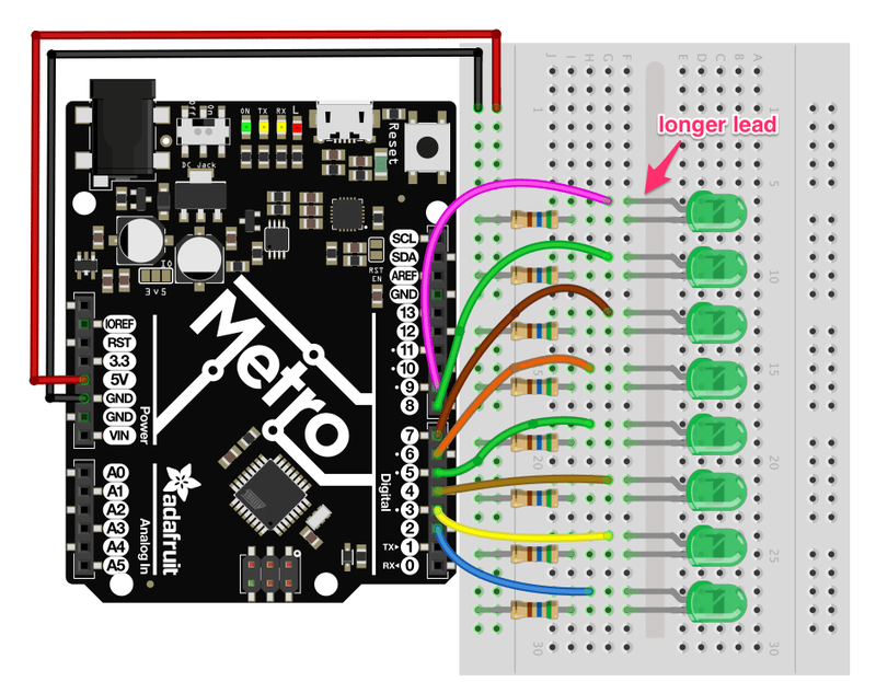
面包板布局
将部件连接到面包板上,如下所示。
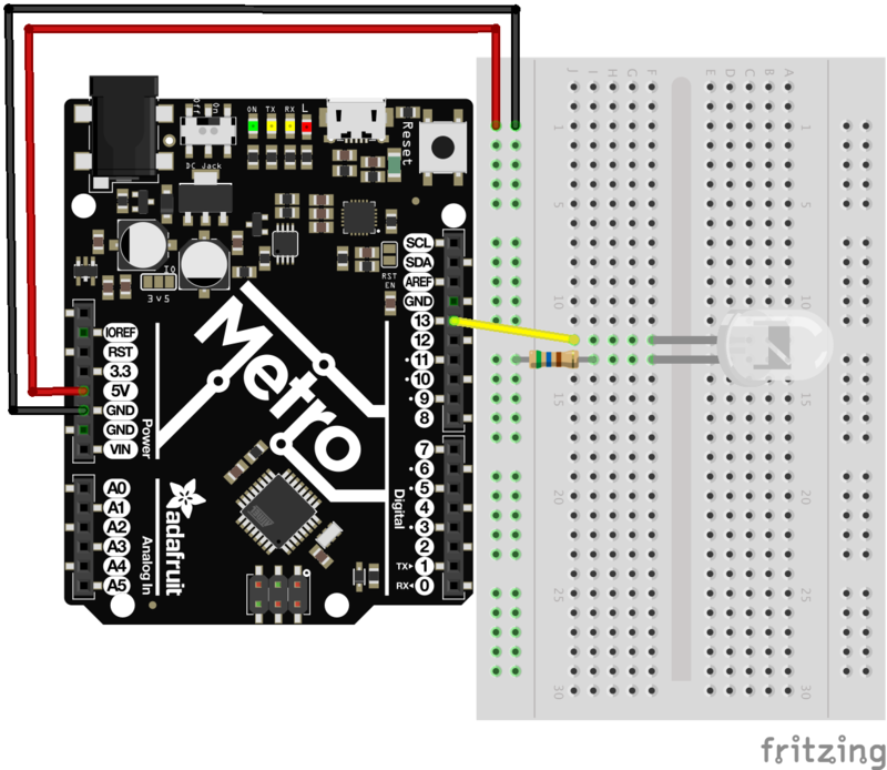
步骤
将LED的较长的一端连接到Metro上的 Pin13 。较短的导线应通过电阻器连接到接地端子。
Metro能够为面包板提供5V电压。使用红色电线将Metro上的 5V引脚连接到面包板的左侧电源导轨。将Metro的 GND引脚连接到电源轨的最右侧。
将560 Ohm电阻器的一根分支连接到电源的较短分支。电阻。该电阻的另一端用黑色电线连接到电源轨(这将是您的地线)。
您完成的电路应该与上面的布局相同。继续操作之前,请确保验证所有连接。
Breadboard布局表
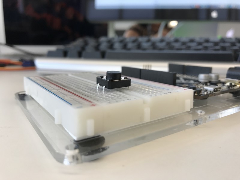
每个电路都附带一个可打印的布局表,以放置在迷你面包板上。您可以使用标题(或磁带)来压住它们,如下所示:
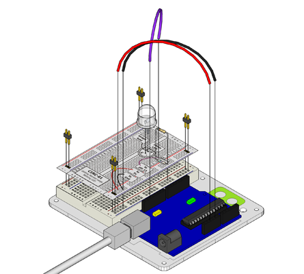
单击此处下载适用于CIRC01的可打印面包板布局表
代码
Arduino编辑器提供了一个使LED闪烁的好例子。无需输入任何内容,只需在Arduino编辑器中单击以下内容: File》 Examples》 1.Basic》 Blink
接下来,我们希望Arduino知道什么当前正在使用板。为此,请导航至工具》板》 Arduino/Genuino Uno
最后,我们需要上传程序。为此,请将Metroboard插入USB端口。然后在工具》串行端口》(您的Metro的串行/COM端口)中选择适当的端口。接下来,通过转到文件》上传(或按键盘上的 ctrl + u )
上传该程序。到Metro上,您应该会看到Metro和面包板上的LED闪烁。
Blink
如果无法从Arduino的示例加载Blink Sketch,可以将以下代码复制并粘贴到编辑器中。
下载:项目Zip 或 CIRC01_BLINK_LED.ino | 在Github上查看
复制代码
/*
Blink
Turns on an LED on for one second, then off for one second, repeatedly.
Most Arduinos have an on-board LED you can control. On the UNO, MEGA and ZERO
it is attached to digital pin 13, on MKR1000 on pin 6. LED_BUILTIN is set to
the correct LED pin independent of which board is used.
If you want to know what pin the on-board LED is connected to on your Arduino model, check
the Technical Specs of your board at https://www.arduino.cc/en/Main/Products
This example code is in the public domain.
modified 8 May 2014
by Scott Fitzgerald
modified 2 Sep 2016
by Arturo Guadalupi
modified 8 Sep 2016
by Colby Newman
*/
// the setup function runs once when you press reset or power the board
void setup() {
// initialize digital pin LED_BUILTIN as an output.
pinMode(LED_BUILTIN, OUTPUT);
}
// the loop function runs over and over again forever
void loop() {
digitalWrite(LED_BUILTIN, HIGH); // turn the LED on (HIGH is the voltage level)
delay(1000); // wait for a second
digitalWrite(LED_BUILTIN, LOW); // turn the LED off by making the voltage LOW
delay(1000); // wait for a second
}
CIRC01是否有问题?
LED不亮?
LED仅在一个方向上工作tion。尝试将其取出并扭曲180度。 (不必担心,向后安装它不会造成永久损害)。
程序未上传?
有时会发生这种情况,最可能的原因是串行端口混乱,您可以在 tools》串行端口》
仍然没有成功吗?
断路不好玩,请在Adafruit支持论坛中发布,我们会尽快与您联系。
变得更好
恭喜您使用Adafruit Metro构建了您的第一个赛道!
让我们一起努力,使您的赛道变得更好,并了解一些以后将很有用的技巧/提示。
更换针脚
LED已连接到引脚13,但我们可以使用METRO的任何引脚。要进行更改,可以将电线插入插针13中,然后将其移至您选择的插针中(从0到13)。
您也可以使用模拟0-5,模拟#0为14,模拟#1是15,等等。
然后在代码中更改所有出现的LED_BUILTIN-》 newpin 。也就是说,将每个LED_BUILTIN更改为8
,然后上传草图:按 ctrl + u
更改闪烁时间
一秒钟一秒钟不满意?在代码中更改以下行:
digitalWrite(LED_BUILTIN, HIGH);
delay(time on); //(seconds * 1000)
digitalWrite(LED_BUILTIN, LOW);
delay(time off); //(seconds * 1000)
控制亮度
带有数字(在/off)控制METRO可以模拟(亮度)方式控制某些引脚。 (有关更多细节,请参见后面的电路)。一起玩吧。通过将所有LED_BUILTIN替换为9
,将LED更改为引脚9 :(也请更改导线)替换 { } 的 loop()带有以下行:
analogWrite(9, new number);
注意在上面的行中,
new number是介于0到255之间的任何数字。0会完全关闭LED。 255是LED的最大亮度。 0到255之间的任何值都是变化的亮度。随便找一个喜欢的人。
衰落
我们将使用另一个附带的示例程序。要打开,请转到文件》示例》 3.模拟》褪色
然后上传到您的板上,观察LED渐入渐出。
CIRC02:8个LED有趣
我们在做什么
我们使一个LED闪烁,现在是时候赌注了。让我们连接八个。我们还将有机会通过创建各种照明序列来扩展Metroa。该电路也是一个不错的设置,可以尝试编写自己的程序并了解Metro的工作原理。
在控制LED的过程中,我们开始研究一些简单的编程方法以使程序保持小尺寸:for()循环和array[]的
零件
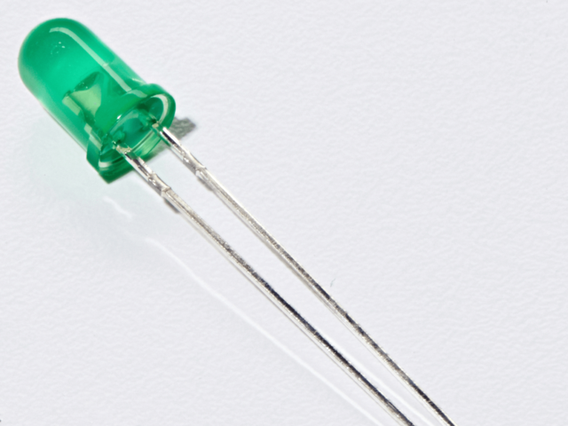
5mm绿色LED
x8(CIRC02需要8个)
如果您想从Adafruit商店订购额外的绿色LED,请单击此处!
560欧姆电阻
x8(对于CIRC02,您需要其中8个电阻)
(它们是相同的您在CIRC01中使用的电阻器,颜色来自:绿色》蓝色》棕色)
如果您想从Adafruit商店订购更多电阻器,请单击此处! (它们的电阻为470欧姆,但可以用)
面包板接线束
如果您想从Adafruit商店订购更多电线,请单击此处!
Adafruit Metro(或Metro Express)+面包板+安装板
如果您尚未组装,我们将为您提供方便的指南!
如果d想从Adafruit商店订购额外的塑料安装板,Adafruit Metro,AdafruitMetro Express或Mini-Breadboard,请点击此处!
接线
面包板布局
步骤
首先,将8个绿色LED连接到面包板上。如布局图中所示,将它们隔开一个孔非常有用。
接下来,从底部的绿色LED开始,将绿色LED的较长边连接到地铁上的数字引脚。从 Pin 2 开始,一直到 Pin 9 。(提示:使用不同的颜色线对您的LED进行颜色编码)
然后,连接8个(560ohm)电阻连接到LED的较短一侧。
Metro能够为面包板提供5V电压。使用红色电线将Metro上的 5V引脚连接到面包板的左侧电源导轨。将Metro的 GND引脚连接到电源轨的最右侧。
完成的电路应与上面的布局相同。继续操作之前,请确保验证所有连接。
单击此处下载适用于CIRC02的可打印面包板布局表
代码
CIRC02代码不是默认的Arduino草图之一。要使用它,请从下面复制代码并将其粘贴到新的Arduino Sketch (ctrl + n/command + n)
下载:Project Zip 或 CIRC02_8_LEDS.ino | 在Github上查看
复制代码
/* ---------------------------------------------------------
* | Arduino Experimentation Kit Example Code |
* | CIRC-02 。: 8 LED Fun :。 (Multiple LEDs) |
* ---------------------------------------------------------
*
* A few Simple LED animations
*
* For more information on this circuit http://tinyurl.com/d2hrud
*
*/
//LED Pin Variables
int ledPins[] = {2,3,4,5,6,7,8,9}; //An array to hold the pin each LED is connected to
//i.e. LED #0 is connected to pin 2, LED #1, 3 and so on
//to address an array use ledPins[0] this would equal 2
//and ledPins[7] would equal 9
/*
* setup() - this function runs once when you turn your Arduino on
* We the three control pins to outputs
*/
void setup()
{
//Set each pin connected to an LED to output mode (pulling high (on) or low (off)
for(int i = 0; i 《 8; i++){ //this is a loop and will repeat eight times
pinMode(ledPins[i],OUTPUT); //we use this to set each LED pin to output
} //the code this replaces is below
/* (commented code will not run)
* these are the lines replaced by the for loop above they do exactly the
* same thing the one above just uses less typing
pinMode(ledPins[0],OUTPUT);
pinMode(ledPins[1],OUTPUT);
pinMode(ledPins[2],OUTPUT);
pinMode(ledPins[3],OUTPUT);
pinMode(ledPins[4],OUTPUT);
pinMode(ledPins[5],OUTPUT);
pinMode(ledPins[6],OUTPUT);
pinMode(ledPins[7],OUTPUT);
(end of commented code)*/
}
/*
* loop() - this function will start after setup finishes and then repeat
* we call a function called oneAfterAnother()。 if you would like a different behaviour
* uncomment (delete the two slashes) one of the other lines
*/
void loop() // run over and over again
{
oneAfterAnotherNoLoop(); //this will turn on each LED one by one then turn each off
//oneAfterAnotherLoop(); //does the same as oneAfterAnotherNoLoop but with
//much less typing
//oneOnAtATime(); //this will turn one LED on then turn the next one
//on turning the
//former off (one LED will look like it is scrolling
//along the line
//inAndOut(); //lights the two middle LEDs then moves them out then back
//in again
}
/*
* oneAfterAnotherNoLoop() - Will light one LED then delay for delayTime then light
* the next LED until all LEDs are on it will then turn them off one after another
*
* this does it without using a loop which makes for a lot of typing.
* oneOnAtATimeLoop() does exactly the same thing with less typing
*/
void oneAfterAnotherNoLoop(){
int delayTime = 100; //the time (in milliseconds) to pause between LEDs
//make smaller for quicker switching and larger for slower
digitalWrite(ledPins[0], HIGH); //Turns on LED #0 (connected to pin 2 )
delay(delayTime); //waits delayTime milliseconds
digitalWrite(ledPins[1], HIGH); //Turns on LED #1 (connected to pin 3 )
delay(delayTime); //waits delayTime milliseconds
digitalWrite(ledPins[2], HIGH); //Turns on LED #2 (connected to pin 4 )
delay(delayTime); //waits delayTime milliseconds
digitalWrite(ledPins[3], HIGH); //Turns on LED #3 (connected to pin 5 )
delay(delayTime); //waits delayTime milliseconds
digitalWrite(ledPins[4], HIGH); //Turns on LED #4 (connected to pin 6 )
delay(delayTime); //waits delayTime milliseconds
digitalWrite(ledPins[5], HIGH); //Turns on LED #5 (connected to pin 7 )
delay(delayTime); //waits delayTime milliseconds
digitalWrite(ledPins[6], HIGH); //Turns on LED #6 (connected to pin 8 )
delay(delayTime); //waits delayTime milliseconds
digitalWrite(ledPins[7], HIGH); //Turns on LED #7 (connected to pin 9 )
delay(delayTime); //waits delayTime milliseconds
//Turns Each LED Off
digitalWrite(ledPins[7], LOW); //Turns on LED #0 (connected to pin 2 )
delay(delayTime); //waits delayTime milliseconds
digitalWrite(ledPins[6], LOW); //Turns on LED #1 (connected to pin 3 )
delay(delayTime); //waits delayTime milliseconds
digitalWrite(ledPins[5], LOW); //Turns on LED #2 (connected to pin 4 )
delay(delayTime); //waits delayTime milliseconds
digitalWrite(ledPins[4], LOW); //Turns on LED #3 (connected to pin 5 )
delay(delayTime); //waits delayTime milliseconds
digitalWrite(ledPins[3], LOW); //Turns on LED #4 (connected to pin 6 )
delay(delayTime); //waits delayTime milliseconds
digitalWrite(ledPins[2], LOW); //Turns on LED #5 (connected to pin 7 )
delay(delayTime); //waits delayTime milliseconds
digitalWrite(ledPins[1], LOW); //Turns on LED #6 (connected to pin 8 )
delay(delayTime); //waits delayTime milliseconds
digitalWrite(ledPins[0], LOW); //Turns on LED #7 (connected to pin 9 )
delay(delayTime); //waits delayTime milliseconds
}
/*
* oneAfterAnotherLoop() - Will light one LED then delay for delayTime then light
* the next LED until all LEDs are on it will then turn them off one after another
*
* this does it using a loop which makes for a lot less typing.
* than oneOnAtATimeNoLoop() does exactly the same thing with less typing
*/
void oneAfterAnotherLoop(){
int delayTime = 100; //the time (in milliseconds) to pause between LEDs
//make smaller for quicker switching and larger for slower
//Turn Each LED on one after another
for(int i = 0; i 《= 7; i++){
digitalWrite(ledPins[i], HIGH); //Turns on LED #i each time this runs i
delay(delayTime); //gets one added to it so this will repeat
} //8 times the first time i will = 0 the final
//time i will equal 7;
//Turn Each LED off one after another
for(int i = 7; i 》= 0; i--){ //same as above but rather than starting at 0 and counting up
//we start at seven and count down
digitalWrite(ledPins[i], LOW); //Turns off LED #i each time this runs i
delay(delayTime); //gets one subtracted from it so this will repeat
} //8 times the first time i will = 7 the final
//time it will equal 0
}
/*
* oneOnAtATime() - Will light one LED then the next turning off all the others
*/
void oneOnAtATime(){
int delayTime = 100; //the time (in milliseconds) to pause between LEDs
//make smaller for quicker switching and larger for slower
for(int i = 0; i 《= 7; i++){
int offLED = i - 1; //Calculate which LED was turned on last time through
if(i == 0) { //for i = 1 to 7 this is i minus 1 (i.e. if i = 2 we will
offLED = 7; //turn on LED 2 and off LED 1)
} //however if i = 0 we don’t want to turn of led -1 (doesn‘t exist)
//instead we turn off LED 7, (looping around)
digitalWrite(ledPins[i], HIGH); //turn on LED #i
digitalWrite(ledPins[offLED], LOW); //turn off the LED we turned on last time
delay(delayTime);
}
}
/*
* inAndOut() - This will turn on the two middle LEDs then the next two out
* making an in and out look
*/
void inAndOut(){
int delayTime = 100; //the time (in milliseconds) to pause between LEDs
//make smaller for quicker switching and larger for slower
//runs the LEDs out from the middle
for(int i = 0; i 《= 3; i++){
int offLED = i - 1; //Calculate which LED was turned on last time through
if(i == 0) { //for i = 1 to 7 this is i minus 1 (i.e. if i = 2 we will
offLED = 3; //turn on LED 2 and off LED 1)
} //however if i = 0 we don’t want to turn of led -1 (doesn‘t exist)
//instead we turn off LED 7, (looping around)
int onLED1 = 3 - i; //this is the first LED to go on ie. LED #3 when i = 0 and LED
//#0 when i = 3
int onLED2 = 4 + i; //this is the first LED to go on ie. LED #4 when i = 0 and LED
//#7 when i = 3
int offLED1 = 3 - offLED; //turns off the LED we turned on last time
int offLED2 = 4 + offLED; //turns off the LED we turned on last time
digitalWrite(ledPins[onLED1], HIGH);
digitalWrite(ledPins[onLED2], HIGH);
digitalWrite(ledPins[offLED1], LOW);
digitalWrite(ledPins[offLED2], LOW);
delay(delayTime);
}
//runs the LEDs into the middle
for(int i = 3; i 》= 0; i--){
int offLED = i + 1; //Calculate which LED was turned on last time through
if(i == 3) { //for i = 1 to 7 this is i minus 1 (i.e. if i = 2 we will
offLED = 0; //turn on LED 2 and off LED 1)
} //however if i = 0 we don’t want to turn of led -1 (doesn‘t exist)
//instead we turn off LED 7, (looping around)
int onLED1 = 3 - i; //this is the first LED to go on ie. LED #3 when i = 0 and LED
//#0 when i = 3
int onLED2 = 4 + i; //this is the first LED to go on ie. LED #4 when i = 0 and LED
//#7 when i = 3
int offLED1 = 3 - offLED; //turns off the LED we turned on last time
int offLED2 = 4 + offLED; //turns off the LED we turned on last time
digitalWrite(ledPins[onLED1], HIGH);
digitalWrite(ledPins[onLED2], HIGH);
digitalWrite(ledPins[offLED1], LOW);
digitalWrite(ledPins[offLED2], LOW);
delay(delayTime);
}
}
编译并上传
在上传之前,重要的一步是验证代码是否可以编译。点击工具栏上的检查按钮(或者,对于Mac用户,在键盘上按 control + r 或 command + r )来编译您的代码。
如果编译没有错误,请将草图上载到电路板(单击此处可获取有关如何从上一个电路执行此操作的更新)。上传后,您应该会看到动画的LED灯显示。
不起作用? CIRC02与GIF不匹配?
某些LED无法点亮
很容易向后插入LED。检查无法正常工作的LED,并确保它们正确定位。
操作不正确
八根电线很容易穿过一对。仔细检查第一个LED是否插入插针2,然后再插入每个插针。
不起作用?
很容易意外地将电线放错了位置,注意。与试图找出问题相比,抽出一切并重新开始通常更容易。
仍然不起作用?
我们会帮助您!在Adafruit支持论坛中发布,我们将尽快与您联系。
变得更好
切换到循环
厌倦了看灯光秀吗?是否要制作自己的动画,更改动画或了解循环功能?让我们使CIRC02更好!
在void loop()过程中,有4行。最后三个都以//开头。这意味着该行是注释(它将不会运行)。我们可以通过删除注释将程序切换为使用循环(如果您想了解有关注释的更多信息,我们将撰写一篇精彩的文章!)。
首先,在void loop()内添加斜杠以禁用oneAfterAnotherNoLoop()运行过程:
oneAfterAnotherNoLoop(); -》 //oneAfterAnotherNoLoop();
接下来,我们将删除注释(斜杠)以使oneAfterAnotherLoop()过程可以循环运行:
//oneAfterAnotherLoop(); -》 oneAfterAnotherLoop();
我们应该立即验证我们的代码是否可以正确编译,单击复选标记(或 ctrl/command + r)。如果一切都编译正确,请继续并将新程序上传( ctrl + u )到您的Metro。
运行程序后,发生了什么变化?
没有变化!两个过程都运行相同的动画。(单击以显示答案)
这两个过程之间有什么区别:oneAfterAnotherNoLoop()和oneAfterAnotherLoop( )?
oneAfterAnotherNoLoop()运行动画而不使用循环这使得很多打字。 使用oneAfterAnotherLoop()将需要更少的键入来运行相同的动画! (单击以显示答案)
其他动画
厌倦了此动画吗?还有更多动画供您玩耍!
要启用它们,请取消注释(只需删除//)第3行和第4行,这样:
//oneOnAtATime();-》 oneOnAtATime();
//inAndOut();-》 inAndOut();
然后将程序( ctrl + u )上传到您的电路板上,并享受新的灯光动画。
制作自己的动画
继续并进入随附的代码,然后开始进行更改。
要告诉Metro 打开LED ,
digitalWrite(pinNumber, HIGH);
如果您想告诉Metro 关闭LED指示灯,
digitalWrite(pinNumber, LOW);
键入!您所做的更改不会破坏任何内容。
CIRC03:旋转电机旋转
我们在做什么
Metro的引脚非常适合直接控制小型电器,例如LED。但是,在处理较大的物品(例如玩具马达或洗衣机)时,需要使用外部晶体管。
晶体管非常有用。它使用小得多的电流来切换大量电流。晶体管具有3个引脚。对于负型( NPN )晶体管,请将负载连接到集电极,将发射极连接到地。然后,当小电流从基极流向发射极时,电流将流经晶体管,并且您的电动机将旋转(这是在将Metropins 设置为高时发生的)。有关晶体管的更深入说明,请单击此处。
字面上有成千上万种不同类型的晶体管,可以使每种情况完美匹配。我们选择了 P2N2222 ,这是一种非常通用的通用晶体管。在我们的案例中,重要的因素是它的最大电压( 40v )和最大电流( 600毫安)都足够我们的玩具电机使用(可以找到完整的详细信息)在其数据表中)。
零件
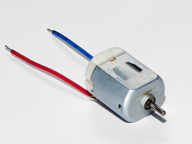
DCToy/Hobby Motor
如果您想从Adafruit商店订购另一台DC Motor,请单击此处!
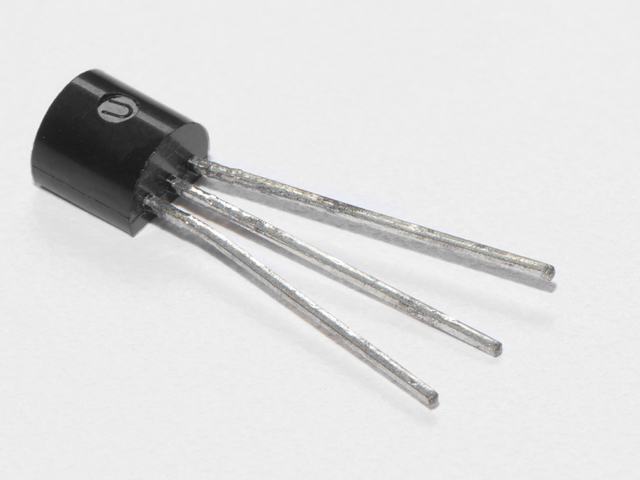
晶体管(PN2222或MPS2222 )
如果您想从Adafruit商店订购额外的NPN晶体管,请单击此处!
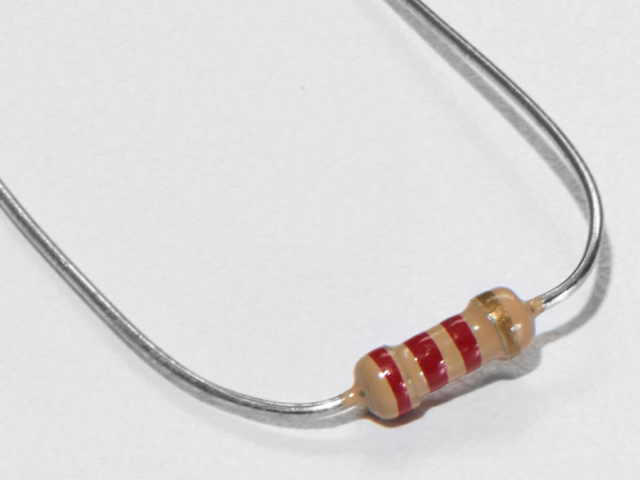
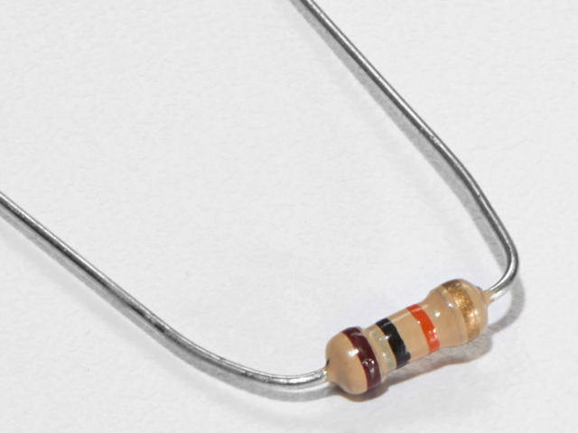
2.2k欧姆电阻
颜色:红色》红色》红色
如果您想从Adafruit商店订购额外的2.2k欧姆电阻,请单击此处!
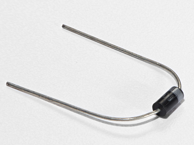
二极管(1N4001 )
如果您想从Adafruit商店订购更多二极管,请单击此处!
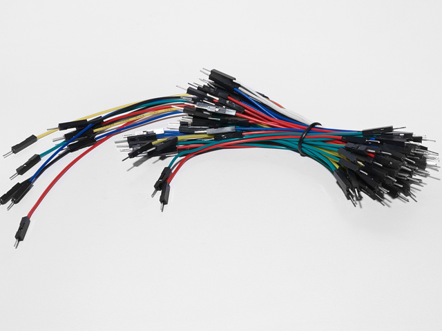
面包板接线束
如果您想从Adafruit商店订购更多电线,请点击此处!
Adafruit Metro(或Metro Express)+面包板+安装板
组装好了,我们有一个方便的指南!
如果您想订购额外的塑料安装板,Adafruit Metro,Adafrui tMetro Express或Adafruit商店的Mini-Breadboard单击此处!
接线
MetroX套件随附的电机的吸力不超过250mA,但是如果您使用其他电机,则很容易吸收1000mA电流,这超出了USB端口的承受能力!如果不确定电机的电流消耗,请通过壁式适配器(而不只是USB)为Metro供电。
之前从CIRC03开始,您应注意以下事项:
晶体管的平侧应面向地铁。
二极管的条纹 侧面应朝向地铁的底部
在此使用的电阻电路不同于过去的两个电路(CIRC01/CIRC02)。确保色带显示为 red》 red》 red 。
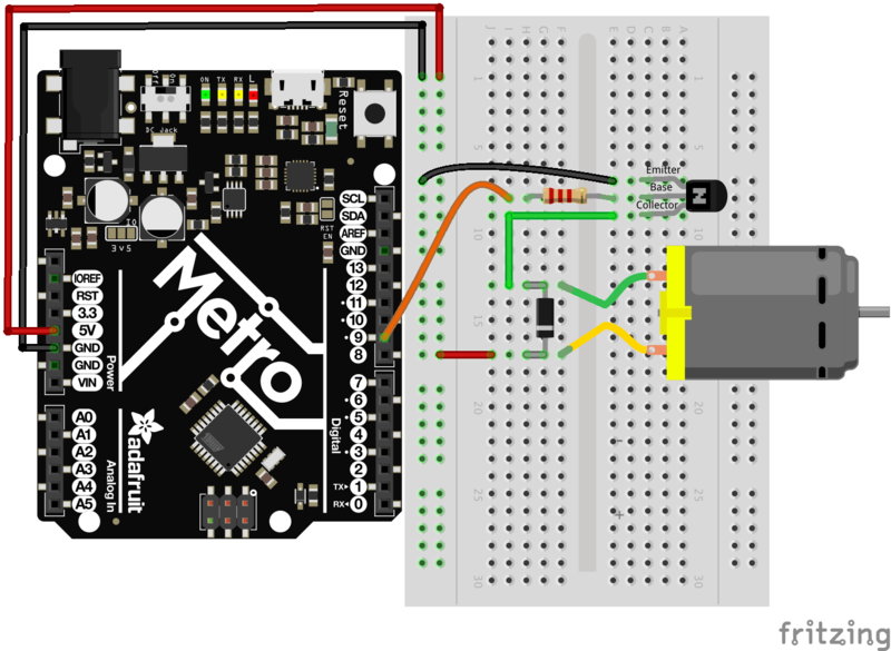
div》 Steps
将Metro上的 GND 和 5V 连接到红色和蓝色电源轨。
确保晶体管的平坦侧面向地铁。将发射器(如上图所示)连接到 GND 导轨。首先将 Base 连接到2.2k Ohm电阻,然后 连接到5V电压轨。暂时离开收集器。
将二极管的条纹引线连接到 5V 干线和非条纹引线
蓝色电动机导线应连接到条纹的电阻器的收集器。
二极管 引线。将红色电动机导线连接到二极管的底部(无条纹)。
重新阅读图表上方的说明,以确保未做任何改动连接组件时出错。 这与现在连接电动机导线的方式无关紧要。
单击此处下载适用于以下情况的可打印面包板布局表: CIRC03
代码
就像在前面的电路中所做的一样,将代码复制并粘贴到新的Arduino草图中。然后编译并将其上传到您的Metro。
Download:Project Zip 或 CIRC03_MOTOR.ino | 在Github上查看
复制代码
/* -----------------------------------------------------------
* | Arduino Experimentation Kit Example Code |
* | CIRC-03 。: Spin Motor Spin :。 (Transistor and Motor) |
* -----------------------------------------------------------
*
* The Arduinos pins are great for driving LEDs however if you hook
* up something that requires more power you will quickly break them.
* To control bigger items we need the help of a transistor.
* Here we will use a transistor to control a small toy motor
*
*
*/
int motorPin = 9; // define the pin the motor is connected to
// (if you use pin 9,10,11 or 3you can also control speed)
/*
* setup() - this function runs once when you turn your Arduino on
* We set the motors pin to be an output (turning the pin high (+5v) or low (ground) (-))
* rather than an input (checking whether a pin is high or low)
*/
void setup()
{
pinMode(motorPin, OUTPUT);
}
/*
* loop() - this function will start after setup finishes and then repeat
* we call a function called motorOnThenOff()
*/
void loop() // run over and over again
{
motorOnThenOff();
//motorOnThenOffWithSpeed();
//motorAcceleration();
}
/*
* motorOnThenOff() - turns motor on then off
* (notice this code is identical to the code we used for
* the blinking LED)
*/
void motorOnThenOff(){
int onTime = 2500; //the number of milliseconds for the motor to turn on for
int offTime = 1000; //the number of milliseconds for the motor to turn off for
digitalWrite(motorPin, HIGH); // turns the motor On
delay(onTime); // waits for onTime milliseconds
digitalWrite(motorPin, LOW); // turns the motor Off
delay(offTime); // waits for offTime milliseconds
}
/*
* motorOnThenOffWithSpeed() - turns motor on then off but uses speed values as well
* (notice this code is identical to the code we used for
* the blinking LED)
*/
void motorOnThenOffWithSpeed(){
int onSpeed = 200; // a number between 0 (stopped) and 255 (full speed)
int onTime = 2500; //the number of milliseconds for the motor to turn on for
int offSpeed = 50; // a number between 0 (stopped) and 255 (full speed)
int offTime = 1000; //the number of milliseconds for the motor to turn off for
analogWrite(motorPin, onSpeed); // turns the motor On
delay(onTime); // waits for onTime milliseconds
analogWrite(motorPin, offSpeed); // turns the motor Off
delay(offTime); // waits for offTime milliseconds
}
/*
* motorAcceleration() - accelerates the motor to full speed then
* back down to zero
*/
void motorAcceleration(){
int delayTime = 50; //milliseconds between each speed step
//Accelerates the motor
for(int i = 0; i 《 256; i++){ //goes through each speed from 0 to 255
analogWrite(motorPin, i); //sets the new speed
delay(delayTime); // waits for delayTime milliseconds
}
//Decelerates the motor
for(int i = 255; i 》= 0; i--){ //goes through each speed from 255 to 0
analogWrite(motorPin, i); //sets the new speed
delay(delayTime); // waits for delayTime milliseconds
}
}
CIRC03遇到问题了吗?
电动机不旋转吗?
如果您采购了自己的晶体管,请仔细检查数据手册以确保其引脚排列与PN2222兼容(许多反向)。
检查电动机
如果您购买了自己的电动机,请仔细检查其是否可以在5伏电压下正常工作消耗太多力量。
仍然有问题吗?
有时Metro板会与计算机断开连接。尝试拔出插头,然后将其重新插入USB端口。
是否尝试了上述步骤?还是不能解决您的问题?
别担心,我们会帮助你!在Adafruit支持论坛中发布,我们将尽快与您联系。
变得更好
控制速度
我们使用Metro的功能来更早地控制LED的亮度。现在,我们将使用相同的功能来控制电动机的速度。
大都会使用称为 Pulse Width Modulation ( PWM 》 )。这取决于METRO能够真正,迅速地运行。 Metro不会直接控制来自引脚的电压,而是会非常快速地打开和关闭引脚。
在计算机世界中,该电压会从0伏到5伏一秒钟,但在人类世界中,我们将其视为电压。例如:如果Metrois PWM在 50%处,我们会看到 50%变暗,因为我们的眼睛不够快,无法看到它闪烁。晶体管具有相同的功能。 (如果您需要对此概念的直观解释,请单击此处)
不相信我吗? 尝试一下!
将下面的代码段复制并粘贴到代码的loop()函数中:
下载:文件
复制代码
// motorOnThenOff();
motorOnThenOffWithSpeed();
// motorAcceleration(); // motorOnThenOff();
motorOnThenOffWithSpeed();
// motorAcceleration();
然后上传程序。
您可以通过将变量onSpeed和offSpeed更改为 0 (停止电动机)和 255 (满功率!)
加速和减速
为什么要以两种速度停止?为什么不对电动机进行加速和减速。
为此,只需将loop()代码更改为:
下载:文件
复制代码
// motorOnThenOff();
// motorOnThenOffWithSpeed();
motorAcceleration(); // motorOnThenOff();
// motorOnThenOffWithSpeed();
motorAcceleration();
然后上传程序并观察电动机缓慢加速到全速然后再次减速。
如果您想更改加速度,请更改变量delayTime(越大,表示加速时间越长)设置为其他值。
CIRC04:单个伺服器
旋转电机很有趣,但是当涉及到需要运动控制的项目时,它们往往会让我们想要更多。
答案是?业余爱好伺服器。它们是批量生产的,可以广泛使用,价格从几美元到几百美元不等。
内部有一个小型变速箱(使机芯更强劲)和一些电子设备(以使其更易于控制)。标准伺服器的位置在0到180度之间。
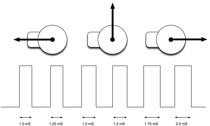
(Simon Monk的Arduino课程14.伺服电机的伺服定位图片)
定位是通过定时脉冲控制的,时间间隔在1.25毫秒(0度)到1.75毫秒(180度)(对于90度为1.5毫秒)。时间因制造商而异。如果每25-50毫秒发送一次脉冲,则伺服将平稳运行。 Adafruit Metro的一大功能是它具有一个软件库,该库可以使用单行代码来控制伺服器
零件
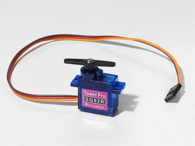
迷你伺服器
如果您想从Adafruit商店订购额外的迷你伺服器,请单击此处!
Adafruit商店中还有许多其他尺寸和类型的伺服器,请查看我们的产品
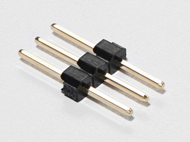
3-Pin标头
如果想要从Adafruit商店订购额外的割台,请单击此处! (这些是40针,但您可以轻松将它们分开)
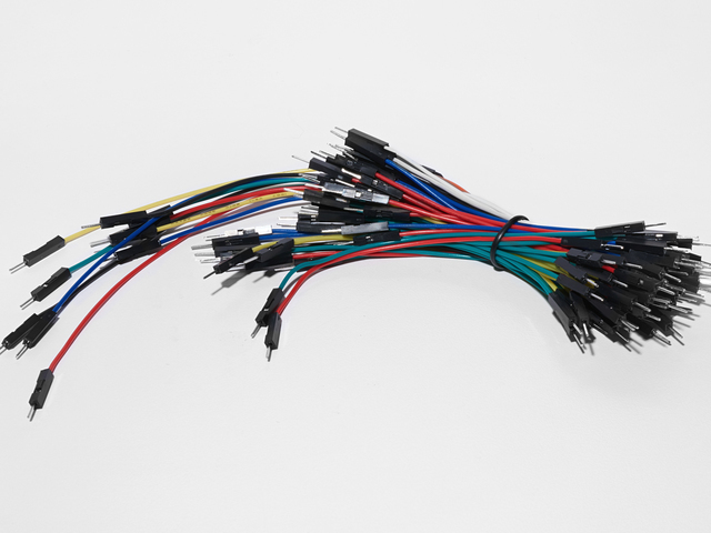
面包板接线束
如果您想从Adafruit商店订购更多电线,请单击此处!
Adafruit Metro(或Metro Express)+面包板+安装板
如果您尚未组装此指南,我们将为您提供方便的指南!
如果您想从Adafruit商店订购额外的塑料安装板,Adafruit Metro,AdafruitMetro Express或Mini-Breadboard,请单击此处!
接线
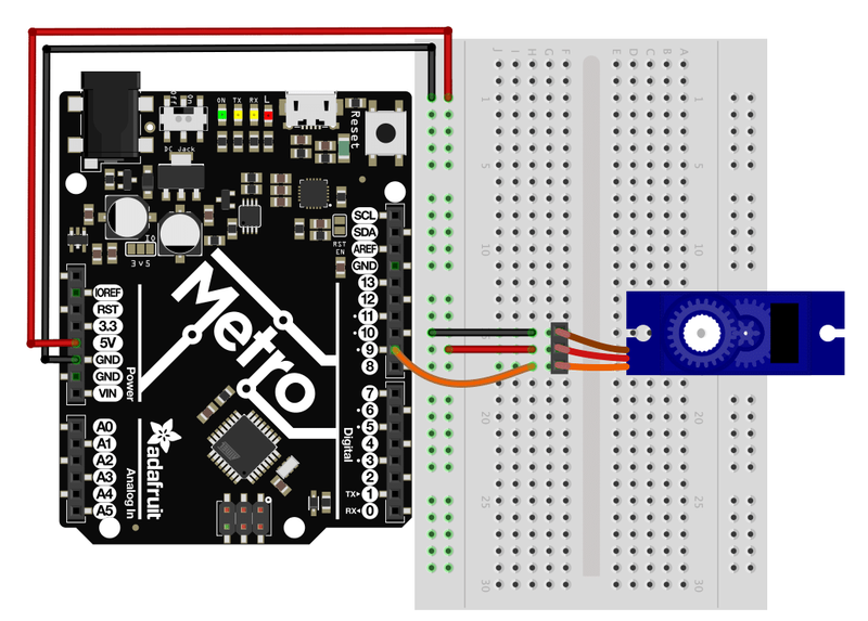
CIRC04的接线比您制作的最后两个电路简单得多。
在地铁上连接 5V 引脚 面包板上的电源轨。
连接Metro上的 GND 引脚 《接地在试验板上的接地轨。
将伺服器的阴端连接到3-Pin接头。
将3-Pin插头插入面包板上的任何行中。
将接地轨连接到棕色伺服线。
将电源轨连接到红色伺服线。
将 Metro针9 连接到橙色伺服导线(信号)。
如果遇到问题,请查看下面的“连接详细信息”以获取接线帮助。
连接详细信息:

面包板伺服
接地导轨黑色/棕色(接地)
电源导轨红色(+ 5V)
Metro Pin 9 橙色(信号)
面包板布局表
单击此处下载适用于CIRC01的可打印面包板布局表
代码
我们要使用的伺服代码包含在Arduino中(就像CIRC001一样),位于:文件》示例》伺服》扫描。
加载草图后,将其编译并上传到您的Metro并查看伺服器的运动!
Sweep
如果您无法从Arduino随附的示例中加载Sweep,则下面是完整的源代码,可以将其复制/粘贴到Arduino编辑器中。
下载:项目Zip 或 CIRC04_SERVO.ino | 在Github上查看
复制代码
/* Sweep
by BARRAGAN
This example code is in the public domain.
modified 8 Nov 2013
by Scott Fitzgerald
http://www.arduino.cc/en/Tutorial/Sweep
*/
#include
Servo myservo; // create servo object to control a servo
// twelve servo objects can be created on most boards
int pos = 0; // variable to store the servo position
void setup() {
myservo.attach(9); // attaches the servo on pin 9 to the servo object
}
void loop() {
for (pos = 0; pos 《= 180; pos += 1) { // goes from 0 degrees to 180 degrees
// in steps of 1 degree
myservo.write(pos); // tell servo to go to position in variable ’pos‘
delay(15); // waits 15ms for the servo to reach the position
}
for (pos = 180; pos 》= 0; pos -= 1) { // goes from 180 degrees to 0 degrees
myservo.write(pos); // tell servo to go to position in variable ’pos‘
delay(15); // waits 15ms for the servo to reach the position
}
}
不起作用?
Servo Not Twisting?
即使使用彩色电线,也仍然很容易将伺服器向后插入。可能是这种情况。如果需要帮助,请检查连接表。
地铁上的引诱和闪烁的LED?
如果伺服器开始运动然后抽动,并且METRO板上有闪烁的指示灯,则说明您使用的电源不足挑战。使用新电池代替USB应该可以解决此问题。
我的伺服器根本没有移动
我们犯了一个或两个错误,就是忘记将电源(红色和棕色的电线)连接到+5伏并接地。再次检查连接是否有故障。
什么都没有,我需要帮助
我们会帮助您!在Adafruit支持论坛中发布,我们将尽快与您联系。
变得更好
电位器控制
我们尚未尝试输入,但是如果您想控制电动机,则电位器是一个不错的选择,而Arduino编辑器提供了一个示例程序。我们将学习CIRC08中的电位计,但是可以通过修改CIRC04来弄湿这种输入。
零件
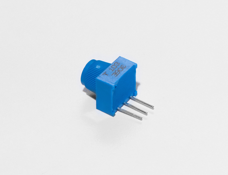
您只需要在此电路中增加一部分:蓝色微调电位器。您可以在框中找到它:
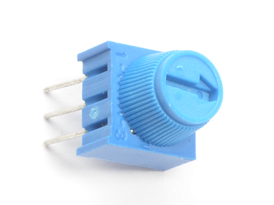
面包板微调电位器-10k
如果您想在Adafruit商店购买一个额外的微调锅,请单击此处!
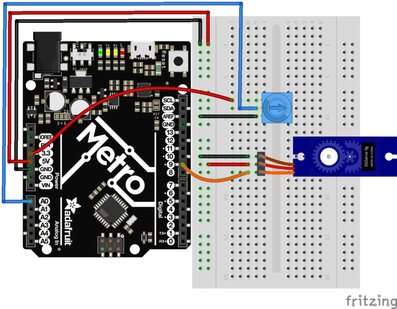
连接电位计
对其进行接线,以使两个最外面的引脚连接到电源和接地导轨。 内部引脚应转到Metro的模拟引脚0。请注意,我们正在使用模拟引脚而不是数字引脚这一次,它们位于地铁左侧的左侧,而不是右侧。
MetroBreadboard图
请小心- Trim电位计连接到3.3 v 输入在Metro上,而不是5V电源线上。
加载示例代码
将电位器控制加载到修订的CIRC04上的代码由Arduino在
文件》伺服》旋钮下提供。草图,编译并将其上传到您的Metro。左右移动电位器,您应该会看到伺服器随之移动。
自定时
尽管使用Metro随附的库很容易控制伺服器,但有时候弄清楚如何自己编写程序还是很有趣的。试试吧!请记住,我们直接控制脉冲,因此您可以使用此方法来控制Metro的20个可用引脚上的伺服器(在执行此操作之前,您需要高度优化此代码)。
其他有趣的伺服创意
Servos可用于进行各种操作东西的。 Adafruit学习系统是查找带有伺服器的有趣项目的绝佳资源。
以下是我们的一些最爱:

动画伺服尾巴:谁能想到没有尾巴?只需一个伺服器和一点点数学,我们就可以实现它!
您曾经想建造一个机器人,但不知道从哪里开始吗?或者。。.您是否正在寻找一个可以割牙的项目?
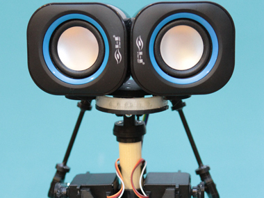
这种伺服控制的动画机器人头使用两个伺服器进行运动,两个扬声器的眼睛和一个LED嘴进行友好的远程控制机器人。
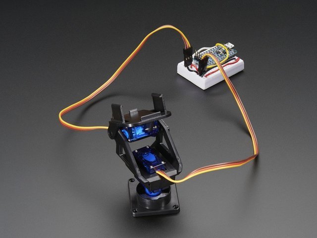
我们组装好的云台套件是使用两个微型伺服器使项目实现全范围运动的理想方法。云台可以左右旋转约180°,并可以上下左右倾斜150°。它还完全组装在一起,包括两个Micro Servos(SG-90或SG-92型)和38mm x 36mm的空间,可安装相机或传感器或任何您喜欢的东西。
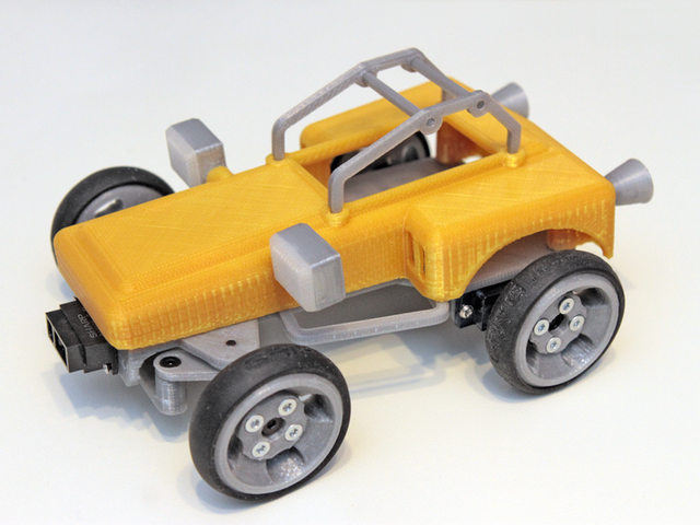
Sandblaster是Blue Buggy的变体Cox International的气动沙地车可以按比例缩小,转换为电动并可以3D打印!
您可以使用它来探索避障,自动导航,无人驾驶车辆设计或辅助远程控制。或者…早上建造,下午比赛!
为您当地的hackerspace/makerspace或全家之夜疯狂!
》
CIRC05:另外8个LED
是时候开始使用它们喜欢的芯片或集成电路了。芯片的外部包装可能非常具有欺骗性。例如,Metroboard上的芯片(微控制器)和我们将在该电路中使用的芯片(移位寄存器)看起来非常相似,但实际上却完全不同。 Metroboard上的Atmel 328p芯片的价格为几美元,而74HC595的价格为几十美分。这是一个很好的介绍性芯片,一旦您习惯了使用它及其数据表,芯片的世界就会变成您的牡蛎。
移位寄存器(也称为a串行到并行转换器),仅使用三个Metropins即可为您提供额外的8个输出(以控制LED等)。它们也可以链接在一起,从而使用相同的四个引脚为您提供几乎无限数量的输出。要使用它,您需要“插入”数据,然后将其锁定(锁存)。
为此,您可以将数据引脚设置为 HIGH 或 LOW ,为时钟脉冲,然后设置再次向数据引脚发送信号并重复时钟脉冲,直到移出8位数据为止。然后,您对锁存器进行脉冲处理,并将8位传输到移位寄存器引脚。听起来很复杂,但是真的很简单。 (单击此处可更深入地了解移位寄存器的工作原理)
零件
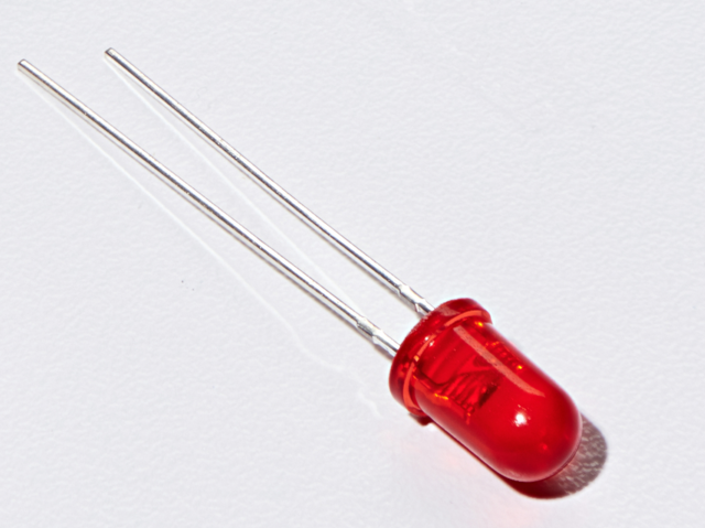
5毫米红色LED
数量:x8
如果您要订购点击此处,更多来自Adafruit商店的红色LED(它们会发出很好的指示灯!)!
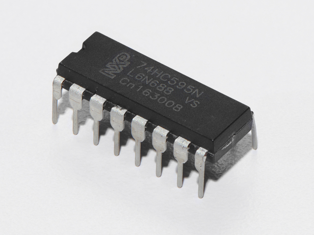
74HC595移位寄存器
如果您要订购更多移位寄存器在Adafruit商店中,请单击此处!
560欧姆电阻器
数量:x8
颜色:绿色》蓝色》棕色
如果您想从Adafruit商店订购更多电阻,请单击此处! (它们的电阻为470欧姆,但可以用)
面包板接线束
如果您想从Adafruit商店订购更多电线,请单击此处!
Adafruit Metro(或Metro Express)+面包板+安装板
如果您尚未组装,我们将为您提供方便的指南!
如果d想从Adafruit商店订购额外的塑料安装板,Adafruit Metro,AdafruitMetro Express或Mini-Breadboard,请点击此处!
接线
CIRC05的接线要比其他电路复杂得多。但是,这并非不可能,只是需要一些时间和耐心。
将此步骤分为三个较大的步骤,依次执行所有步骤,您将获得有趣的LED表演! p》
ChipOrientation
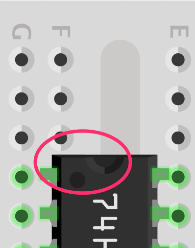
移位寄存器的放置位置应使半月圆圈应面向面包板的顶部。
步骤1:连接电源/GND
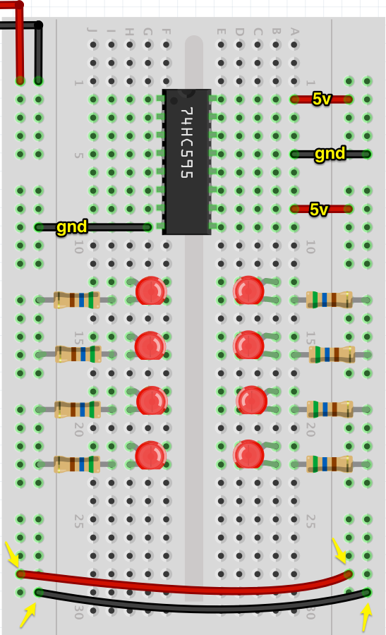
在没有太多电线的情况下,更容易查看该图。首先,我们连接电路上的所有电源和接地点。 注意,我们正在通过将左侧导轨连接到右侧导轨来扩展电源和接地导轨。这是为了便于访问并使所有内容保持整洁。
我们还将插入电阻器。电阻插入LED的阴极(较短端),然后接地。
第2步:将数据引脚连接到Metro
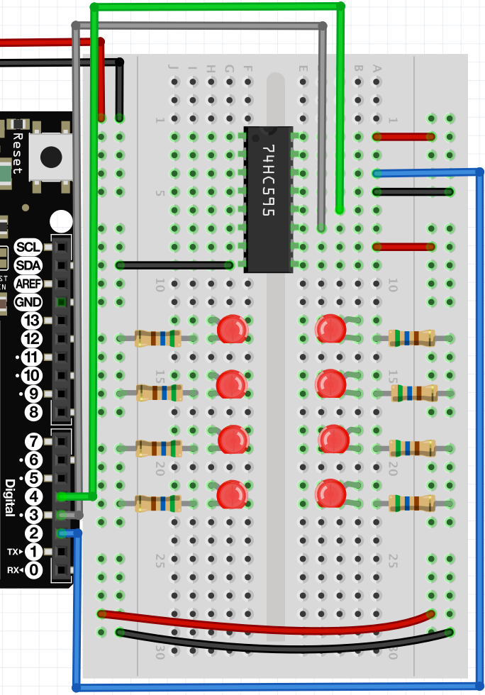
地铁上的插针2、3和4对应于数据(插针14)
上的strong》,锁存(引脚12)和时钟(引脚11)。
第3步:连接LED
下一步是连接LED到移位寄存器。我们在下面提供了一个方便的说明,以及最终的图表。
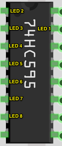
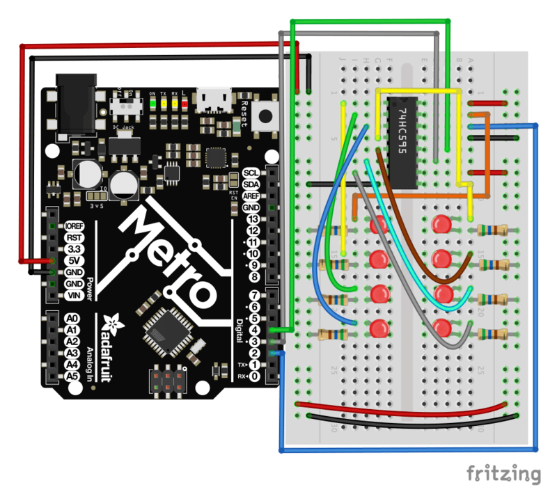
完成LED布线后,请仔细检查全部根据最终图进行接线。之后,转到“代码”部分。
面包板布局表
单击此处下载适用于CIRC05的可打印面包板布局表
代码
将下面的代码复制/粘贴到一个空白的草图中。然后编译并将其上传到您的Metro。
下载:Project Zip 或 CIRC05_SHIFT_REGISTER.ino | 在Github上查看
复制代码
/* ---------------------------------------------------------
* | Arduino Experimentation Kit Example Code |
* | CIRC-05 。: 8 More LEDs :。 (74HC595 Shift Register) |
* ---------------------------------------------------------
*
* We have already controlled 8 LEDs however this does it in a slightly
* different manner. Rather than using 8 pins we will use just three
* and an additional chip.
*
*
*/
//Pin Definitions
//Pin Definitions
//The 74HC595 uses a serial communication
//link which has three pins
int data = 2;
int clock = 3;
int latch = 4;
//Used for single LED manipulation
int ledState = 0;
const int ON = HIGH;
const int OFF = LOW;
/*
* setup() - this function runs once when you turn your Arduino on
* We set the three control pins to outputs
*/
void setup()
{
pinMode(data, OUTPUT);
pinMode(clock, OUTPUT);
pinMode(latch, OUTPUT);
}
/*
* loop() - this function will start after setup finishes and then repeat
* we set which LEDs we want on then call a routine which sends the states to the 74HC595
*/
void loop() // run over and over again
{
int delayTime = 100; //the number of milliseconds to delay between LED updates
for(int i = 0; i 《 256; i++){
updateLEDs(i);
delay(delayTime);
}
}
/*
* updateLEDs() - sends the LED states set in ledStates to the 74HC595
* sequence
*/
void updateLEDs(int value){
digitalWrite(latch, LOW); //Pulls the chips latch low
shiftOut(data, clock, MSBFIRST, value); //Shifts out the 8 bits to the shift register
digitalWrite(latch, HIGH); //Pulls the latch high displaying the data
}
/*
* updateLEDsLong() - sends the LED states set in ledStates to the 74HC595
* sequence. Same as updateLEDs except the shifting out is done in software
* so you can see what is happening.
*/
void updateLEDsLong(int value){
digitalWrite(latch, LOW); //Pulls the chips latch low
for(int i = 0; i 《 8; i++){ //Will repeat 8 times (once for each bit)
int bit = value & B10000000; //We use a “bitmask” to select only the eighth
//bit in our number (the one we are addressing this time through
value = value 《《 1; //we move our number up one bit value so next time bit 7 will be
//bit 8 and we will do our math on it
if(bit == 128){digitalWrite(data, HIGH);} //if bit 8 is set then set our data pin high
else{digitalWrite(data, LOW);} //if bit 8 is unset then set the data pin low
digitalWrite(clock, HIGH); //the next three lines pulse the clock pin
delay(1);
digitalWrite(clock, LOW);
}
digitalWrite(latch, HIGH); //pulls the latch high shifting our data into being displayed
}
//These are used in the bitwise math that we use to change individual LEDs
//For more details http://en.wikipedia.org/wiki/Bitwise_operation
int bits[] = {B00000001, B00000010, B00000100, B00001000, B00010000, B00100000, B01000000, B10000000};
int masks[] = {B11111110, B11111101, B11111011, B11110111, B11101111, B11011111, B10111111, B01111111};
/*
* changeLED(int led, int state) - changes an individual LED
* LEDs are 0 to 7 and state is either 0 - OFF or 1 - ON
*/
void changeLED(int led, int state){
ledState = ledState & masks[led]; //clears ledState of the bit we are addressing
if(state == ON){ledState = ledState | bits[led];} //if the bit is on we will add it to ledState
updateLEDs(ledState); //send the new LED state to the shift register
}
不起作用?
Metro的电源LED熄灭
芯片向后插入。关闭Metro的电源,然后旋转芯片,使芯片上的半月形切口朝向面包板的顶部。
仍然无效?
对不起,听起来像是破唱片,但请务必确保您的接线是正确的。如果您不确定:取出所有东西,然后重新开始。
是否感到沮丧?
此电路既简单又复杂,请让我们知道您对它的失望,以便我们在以后的版本中解决该问题。
变得更好
艰难的方式
地铁使复杂的动作非常简单。一个完美的例子是数据的转移和处理。但是,Metro的优点之一就是您可以调整要实现的难度。
在loop()中,将updateLEDs(i);切换为updateLEDsLong(i);
您这次运行时是否注意到任何不同?
您不应该拥有的!代码执行的动作没有什么不同。通过使用串行外围设备接口,将代码更改为一次与LED通讯。
控制单个LED
就像CIRC02一样,您可以单独控制面包板上的LED。八个LED的当前状态以一个8位值存储(有关此主题的更多信息,我们有关于Binary和Hex的Collin’s Lab很棒的视频)。提供的代码已经处理了位操作。
要控制单个LED,我们将loop()中的代码替换为以下内容:
下载:文件
复制代码
int delayTime = 100; // # of ms to delay btween LED updates
for(int i=0; i《8; i++){
changeLED(i, ON);
delay(delayTime);
}
for(int i=0;i《8;i++){
changeLED(i,OFF);
delay(delayTime);
}
int delayTime = 100; // # of ms to delay btween LED updates
for(int i=0; i《8; i++){
changeLED(i, ON);
delay(delayTime);
}
for(int i=0;i《8;i++){
changeLED(i,OFF);
delay(delayTime);
}
然后,将其编译并上传到Metro。该代码将导致LED依次点亮,然后熄灭。通读代码和链接以更好地了解其工作原理。
更多动画
如果您执行的是CIRC02,则“做得更好”部分中有一部分涉及添加其他动画。在此电路中更改LED的格式将相似。
CIRC02可让您使用
digitalWrite(LED, state)
CIRC05使用changeLED()例程执行相同的操作:
changeLED(LED, state)
您可以通过以下方式重新使用CIRC02的其他动画中的代码: CIRC02进入此草图,然后将所有digitalWrite()例程更改为changeLED()。您还需要更改其他一些内容,只需遵循编译器错误即可解决。
CIRC06:压电音乐
至此,我们已经控制了光,运动和电子。接下来让我们解决声音。但是声音是一种 analog 现象,我们的 digital Metro将如何应对?我们将再次依靠其令人难以置信的速度来模拟模拟行为。
我们将在Metro的数字引脚之一上附加一个压电元件。压电元件每次在受到电流脉冲时都会发出喀哒声。如果我们以适当的频率(例如每秒440次使音符 A变成音符)对其进行脉动,则这些点击会同时产生音符。
让我们开始实验并让您的Metro播放“ Twinkle Twinkle Little Star”!
零件
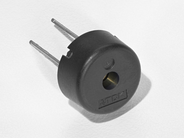
Piezo 蜂鸣器
如果您想从Adafruit商店订购另一个Pizeo蜂鸣器,请单击此处!
面包板接线束
如果您想从Adafruit商店订购更多电线,请单击此处!
Adafruit Metro(或Metro Express)+面包板+安装板
如果您尚未组装此手册,我们将为您提供方便的指南!
如果您愿意或在Adafruit商店中购买额外的塑料安装板,Adafruit Metro,AdafruitMetro Express或Mini-Breadboard,请单击此处!
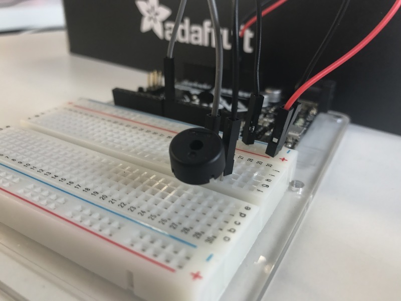
接线
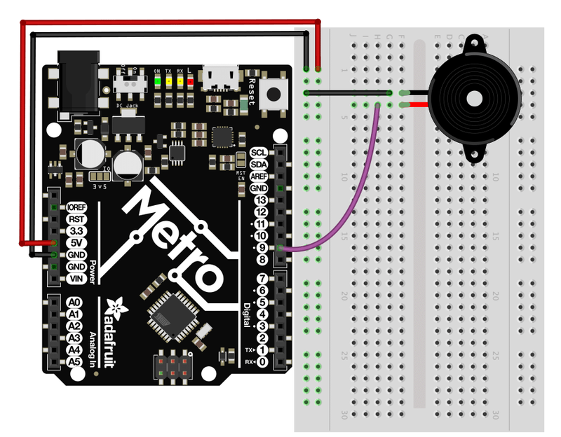
比CIRC05接线容易得多:
连接GND和5V电压轨。
将压电的一侧连接到 GND
将压电的另一端连接到Metro的数字引脚9
面包板布局表
单击此处下载适用于CIRC06的可打印面包板布局表
代码
将下面的代码复制/粘贴到一个空白的草图中。然后编译并将其上传到您的Metro。
下载:Project Zip 或 CIRC06_PIEZO.ino | 在Github上查看
复制代码
// CIRC06 - Music with Piezo
int speakerPin = 9;
int length = 15; // the number of notes
char notes[] = “ccggaagffeeddc ”; // a space represents a rest
int beats[] = { 1, 1, 1, 1, 1, 1, 2, 1, 1, 1, 1, 1, 1, 2, 4 };
int tempo = 300;
void playNote(char note, int duration) {
char names[] = { ‘c’, ‘d’, ‘e’, ‘f’, ‘g’, ‘a’, ‘b’, ‘C’ };
int tones[] = { 1915, 1700, 1519, 1432, 1275, 1136, 1014, 956 };
// play the tone corresponding to the note name
for (int i = 0; i 《 8; i++) {
if (names[i] == note) {
tone(speakerPin, tones[i], duration);
}
}
}
void setup() {
pinMode(speakerPin, OUTPUT);
}
void loop() {
for (int i = 0; i 《 length; i++) {
if (notes[i] == ‘ ’) {
delay(beats[i] * tempo); // rest
} else {
playNote(notes[i], beats[i] * tempo);
}
// pause between notes
delay(tempo / 2);
}
}
不起作用?
扬声器没有声音
给出尺寸压电元件的形状和形状很容易错过面包板上的正确孔。尝试仔细检查其位置。
在播放旋律时无法思考吗?
只是因为想起压电元件,上传程序,然后重新插入。
对一闪一闪的小星星感到厌倦了吗?
代码已编写,因此您可以轻松添加自己的歌曲,请查看“使之更好”部分,以获取有关修改代码的更多信息。
变得更好
每个音符的时机是根据变量计算的,因此我们可以调整每个音符的声音或时机。要更改旋律的速度,我们只需要更改一行:
int tempo = 300; -》 int tempo = (new #);
将new #更改为更大的数字可以降低音乐的速度,或者将其更改为较小的数字可以提高音乐的速度!
调整音符
如果您担心音符有点过时,也可以解决此问题。注释是根据程序顶部注释块中的公式计算得出的。但是要调整单个音符,只需向上或向下调整它们在tones []数组中的值,直到听起来正确为止。每个音符在名称[]数组中均与其名称匹配。
例如:如果我们希望 c(c = 1915)具有更高的音高,则需要找到它的初始值:
char names[] = { ‘c’, ‘d’, ‘e’, ‘f’, ‘g’, ‘a’, ‘b’, ‘C’ };
int tones[] = { 1915, 1700, 1519, 1432, 1275, 1136, 1014, 956 };
,然后将tones []中的数字更改为更大的数字,让我们开始吧 1975 :
char names[] = { ‘c’, ‘d’, ‘e’, ‘f’, ‘g’, ‘a’, ‘b’, ‘C’ };
int tones[] = { 1975, 1700, 1519, 1432, 1275, 1136, 1014, 956 };
组成自己的旋律:
程序已预设为播放“ Twinkle Twinkle Little”
一首歌曲采用一个整数(int length)和两个数组(char notes[]和int beats[] )。
int length-定义音符数量
char notes[]-定义每个音符
int beat[]-定义每个音符将播放多长时间
Twinkle Twinkle Little Star
下载:文件
复制代码
int length = 15;
char notes[] = {“ccggaagffeeddc”};
int beats[] = { 1, 1, 1, 1, 1, 1, 2, 1, 1, 1, 1, 1, 1, 2, 4 }; int length = 15;
char notes[] = {“ccggaagffeeddc”};
int beats[] = { 1, 1, 1, 1, 1, 1, 2, 1, 1, 1, 1, 1, 1, 2, 4 };
生日快乐(第一行)
下载:文件
复制代码
int length = 13;
char notes[] = {“ccdcfeccdcgf”};
int beats[] = {1,1,1,1,1,2,1,1,1,1,1,2,4}; int length = 13;
char notes[] = {“ccdcfeccdcgf”};
int beats[] = {1,1,1,1,1,2,1,1,1,1,1,2,4};
要熟悉代码的工作方式,始终最好看一下示例。以上是两首歌。运行它们,然后修改它们以组成您自己的旋律。
CIRC07:按下按钮
到目前为止,我们完全专注于产出。现在是让我们的Metroto聆听,观看和感受的时候了。我们将从一个简单的按钮开始。
连接按钮很简单。上拉电阻只有一个组件,可能看起来不合适。之所以会包含此内容,是因为Metro不会以与我们相同的方式进行感知(即:按钮按下,按钮未按下)。相反,它查看引脚上的电压并确定它是 HIGH 还是 LOW 。按下该按钮时,将其设置为将Metro的引脚 LOW 拉低,但是,如果未按下该按钮,则引脚的电压将浮动(导致偶然的错误)。为了使Metroto在未按下按钮时可靠地将引脚读取为HIGH,我们在电路中添加了上拉电阻。
零件
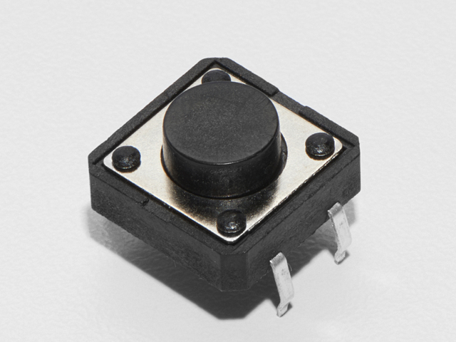
按钮 数量:x2
如果您想订购更多按钮在Adafruit商店中,请单击此处!

5毫米红色LED
如果您想从Adafruit订购更多红色LED(它们可以很好地显示指示灯!)商店,请点击此处!
10K欧姆电阻
颜色:棕色》黑色》橙色
数量:x2
如果您想从Adafruit商店订购更多的10k欧姆上拉电阻,请单击此处!
560欧姆电阻
颜色:绿色》蓝色》棕色
如果您想从Adafruit商店订购更多电阻,请单击此处! (它们的电阻为470欧姆,但可以用)
面包板接线束
如果您想从Adafruit商店订购更多电线,请单击此处!
Adafruit Metro(或Metro Express)+面包板+安装板
如果您尚未组装,我们将为您提供方便的指南!
如果d想从Adafruit商店订购额外的塑料安装板,Adafruit Metro,AdafruitMetro Express或Mini-Breadboard,请点击此处!
接线
CIRC07的接线很简单-电线连接到Metrosit上的开关端子和电阻之间的数字引脚。
专业提示:将按钮推入面包板时,注意不要将腿向外弯曲太多,否则不会与面包板接触。就位在面包板的空隙中。
面包板布局表
单击此处下载适用于CIRC07的可打印面包板布局表
代码
此代码在Arduino编辑器中为您提供:文件》示例》 2.数字》按钮。将其加载到Arduino编辑器,然后编译并将其上传到您的Metro。
代码:
下载:Project Zip 或 CIRC07_BUTTON.ino | 在Github上查看
复制代码
/*
Button
Turns on and off a light emitting diode(LED) connected to digital pin 13,
when pressing a pushbutton attached to pin 2.
The circuit:
- LED attached from pin 13 to ground
- pushbutton attached to pin 2 from +5V
- 10K resistor attached to pin 2 from ground
- Note: on most Arduinos there is already an LED on the board
attached to pin 13.
created 2005
by DojoDave
modified 30 Aug 2011
by Tom Igoe
This example code is in the public domain.
http://www.arduino.cc/en/Tutorial/Button
*/
// constants won‘t change. They’re used here to set pin numbers:
const int buttonPin = 2; // the number of the pushbutton pin
const int ledPin = 13; // the number of the LED pin
// variables will change:
int buttonState = 0; // variable for reading the pushbutton status
void setup() {
// initialize the LED pin as an output:
pinMode(ledPin, OUTPUT);
// initialize the pushbutton pin as an input:
pinMode(buttonPin, INPUT);
}
void loop() {
// read the state of the pushbutton value:
buttonState = digitalRead(buttonPin);
// check if the pushbutton is pressed. If it is, the buttonState is HIGH:
if (buttonState == HIGH) {
// turn LED on:
digitalWrite(ledPin, HIGH);
} else {
// turn LED off:
digitalWrite(ledPin, LOW);
}
}
无效?
灯不亮
按钮正方形,因此很容易以错误的方式放置它。将其旋转90度,看看它是否开始工作。
灯光不褪色
我们经常犯一些愚蠢的错误,当您从简单打开关闭到褪色时,请记住将LED电线从插针13移到引脚9。
感觉不知所措?
不用担心,这些电路都被超级精简地简化了组件的制作很容易,但是一旦将它们放在一起,便是极限。
变得更好
电灯开关
有点让人不知所措(“我不需要地铁就能完成 this !”),让我们使用地铁来做一些更复杂的事情。我们将做一个电灯开关。面包板上的一个按钮将打开灯,另一个按钮将其关闭!
这非常简单,我们只需要更改几行代码即可:
下载:文件
复制代码
int ledPin = 13; // choose the pin for the LED
int buttonPin1 = 3; // button 1
int buttonPin2 = 2; // button 2
void setup() {
pinMode(ledPin, OUTPUT); // declare LED as output
pinMode(buttonPin1, INPUT); // make button 1 an input
pinMode(buttonPin1, INPUT); // make button 2 an input
}
void loop() {
if (digitalRead(buttonPin1) == LOW) {
digitalWrite(ledPin, LOW); // turn LED OFF
}
else if (digitalRead(buttonPin2) == LOW) {
digitalWrite(ledPin, HIGH); // turn LED ON
}
} int ledPin = 13; // choose the pin for the LED
int buttonPin1 = 3; // button 1
int buttonPin2 = 2; // button 2
void setup() {
pinMode(ledPin, OUTPUT); // declare LED as output
pinMode(buttonPin1, INPUT); // make button 1 an input
pinMode(buttonPin1, INPUT); // make button 2 an input
}
void loop() {
if (digitalRead(buttonPin1) == LOW) {
digitalWrite(ledPin, LOW); // turn LED OFF
}
else if (digitalRead(buttonPin2) == LOW) {
digitalWrite(ledPin, HIGH); // turn LED ON
}
}
将代码复制并粘贴到空白草图中,将其上传到电路板上,然后开始打开和关闭LED。
褪色
让我们使用按钮来控制模拟信号。为此,您需要将连接LED的电线从9中的 Pi n 13 更改为 P
在代码中,更改:
int ledPin = 13; -》 int ledPin = 9;
下一步,更改 loop()读取的代码:
下载:文件
复制代码
int value = 0;
void loop() {
if(digitalRead(buttonPin1) == LOW){
value--;
}
else if(digitalRead(buttonPin2) == LOW){
value++;
}
value = constrain(value, 0, 255);
analogWrite(ledPin, value);
delay(10);
} int value = 0;
void loop() {
if(digitalRead(buttonPin1) == LOW){
value--;
}
else if(digitalRead(buttonPin2) == LOW){
value++;
}
value = constrain(value, 0, 255);
analogWrite(ledPin, value);
delay(10);
}
更改淡入淡出速度
如果您希望LED淡入或淡出,则只需更改一行代码:
delay(10); -》 delay(new #);
要淡化更快:将数字减小。
要使变慢淡入淡出:请增大数字。
CIRC08:扭曲
除了数字引脚外,Metro还具有6个可用于模拟输入的引脚。
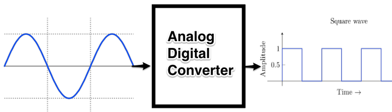
这些输入采用电压(从0到5伏)并将其转换为数字在0(0伏特)和1023(5伏特)(10位分辨率)之间。
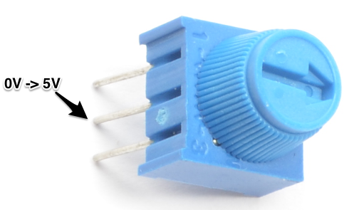
利用这些输入的非常有用的设备是电位计(也称为可变电阻器)。当它的外部引脚上连接有5伏电压时,中间引脚将读取0到5伏之间的某个值,具体取决于其旋转角度(即,中间2.5伏)。然后,我们可以将返回的值用作程序中的变量。
零件
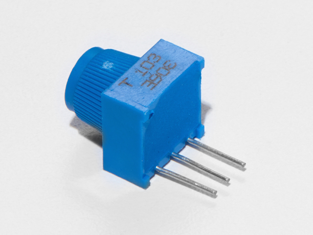
面包板微调电位器-10k
如果您想从Adafruit商店购买一个额外的修剪锅,请单击此处!

5mm红色LED
如果您想从Adafruit商店订购更多的红色LED(它们使指示灯很好!),请单击此处!
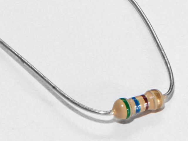
560欧姆电阻
颜色:绿色》蓝色》棕色
如果您想从Adafruit商店请点击这里! (它们的电阻为470欧姆,但可以用)
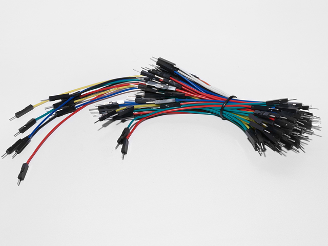
面包板接线束
如果您想从Adafruit商店订购更多电线,请单击此处!
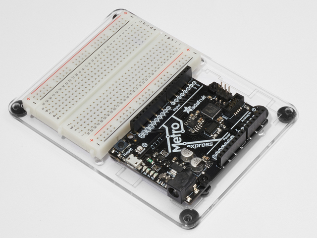
Adafruit Metro(或Metro Express)+面包板+安装板
如果您尚未组装,我们将为您提供方便的指南!
如果d想从Adafruit商店订购额外的塑料安装板,Adafruit Metro,AdafruitMetro Express或Mini-Breadboard,请点击此处!
接线
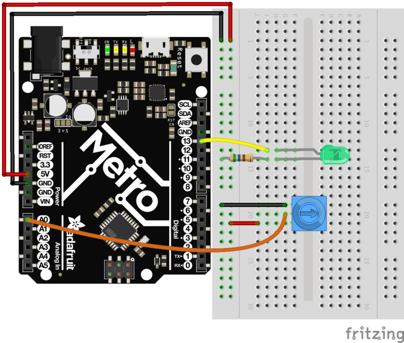
CIRC08可以快速接线:
LED的长端连接到560欧姆的电阻,该电阻接地。
较短的(阴极)端连接到地铁的数字引脚13
电位器的中间引脚连接到模拟引脚0
电位计连接到 5V 和 GND 电源轨。
可打印的面包板图纸
点击此处下载适用于CIRC08的可打印的面包板布局图纸
Metro Express的接线
如果您使用的是Adafruit Metro Express,则应使用以下接线。如果您不确定自己拥有什么板,请检查此页面。
面包板上的电源轨应连接到Metro Express上的3.3V引脚
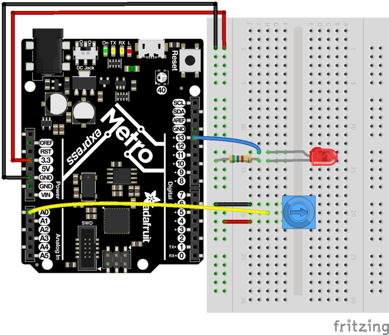
代码
Arduino包含此示例,在以下位置找到它:文件》示例》 3.Analog》模拟输入
然后编译并将其上传到您的Metro。调整电位计以更改LED的亮度。
如果找不到或加载示例,代码如下:
下载:Project Zip 或 CIRC08_POTENTIOMETER。 ino | 在Github上查看
复制代码
/*
Analog Input
Demonstrates analog input by reading an analog sensor on analog pin 0 and
turning on and off a light emitting diode(LED) connected to digital pin 13.
The amount of time the LED will be on and off depends on
the value obtained by analogRead()。
The circuit:
* Potentiometer attached to analog input 0
* center pin of the potentiometer to the analog pin
* one side pin (either one) to ground
* the other side pin to +5V
* LED anode (long leg) attached to digital output 13
* LED cathode (short leg) attached to ground
* Note: because most Arduinos have a built-in LED attached
to pin 13 on the board, the LED is optional.
Created by David Cuartielles
modified 30 Aug 2011
By Tom Igoe
This example code is in the public domain.
http://www.arduino.cc/en/Tutorial/AnalogInput
*/
int sensorPin = A0; // select the input pin for the potentiometer
int ledPin = 13; // select the pin for the LED
int sensorValue = 0; // variable to store the value coming from the sensor
void setup() {
// declare the ledPin as an OUTPUT:
pinMode(ledPin, OUTPUT);
}
void loop() {
// read the value from the sensor:
sensorValue = analogRead(sensorPin);
// turn the ledPin on
digitalWrite(ledPin, HIGH);
// stop the program for milliseconds:
delay(sensorValue);
// turn the ledPin off:
digitalWrite(ledPin, LOW);
// stop the program for for milliseconds:
delay(sensorValue);
}
不起作用?
偶尔工作
这很可能是由于与电位器的引脚。通常可以通过向下点击电位器来解决此问题。
不起作用?
确保您没有将电位计的抽头意外连接到数字引脚0而不是模拟引脚0(电源引脚下方的引脚行)。
是否仍然向后?
您可以尝试颠倒操作电路。有时这会有所帮助。
使用Arduino串行绘图仪
我们将开始绘制。。.值! Arduino带有一个很酷的工具,称为串行绘图仪。它可以实时显示变量。这对于可视化数据,对代码进行故障排除以及将变量可视化为波形非常有用。
我们首先需要修改CIRC08的代码。将以下代码复制并粘贴到Arduino编辑器中。然后编译并上传。
下载:文件
复制代码
/*
Analog Input, but with Serial Plotter!
Demonstrates analog input by reading an analog sensor on analog pin 0 and
turning on and off a light emitting diode(LED) connected to digital pin 13.
The amount of time the LED will be on and off depends on
the value obtained by analogRead()。
The circuit:
* Potentiometer attached to analog input 0
* center pin of the potentiometer to the analog pin
* one side pin (either one) to ground
* the other side pin to +5V
* LED anode (long leg) attached to digital output 13
* LED cathode (short leg) attached to ground
* Note: because most Arduinos have a built-in LED attached
to pin 13 on the board, the LED is optional.
Created by David Cuartielles
modified 30 Aug 2011
By Tom Igoe
This example code is in the public domain.
http://www.arduino.cc/en/Tutorial/AnalogInput
*/
int sensorPin = A0; // select the input pin for the potentiometer
int ledPin = 13; // select the pin for the LED
int sensorValue = 0; // variable to store the value coming from the sensor
void setup() {
// declare the ledPin as an OUTPUT:
pinMode(ledPin, OUTPUT);
// begin the serial monitor @ 9600 baud
Serial.begin(9600);
}
void loop() {
// read the value from the sensor:
sensorValue = analogRead(sensorPin);
Serial.println(sensorValue);
Serial.print(“ ”);
delay(20);
} /*
Analog Input, but with Serial Plotter!
Demonstrates analog input by reading an analog sensor on analog pin 0 and
turning on and off a light emitting diode(LED) connected to digital pin 13.
The amount of time the LED will be on and off depends on
the value obtained by analogRead()。
The circuit:
* Potentiometer attached to analog input 0
* center pin of the potentiometer to the analog pin
* one side pin (either one) to ground
* the other side pin to +5V
* LED anode (long leg) attached to digital output 13
* LED cathode (short leg) attached to ground
* Note: because most Arduinos have a built-in LED attached
to pin 13 on the board, the LED is optional.
Created by David Cuartielles
modified 30 Aug 2011
By Tom Igoe
This example code is in the public domain.
http://www.arduino.cc/en/Tutorial/AnalogInput
*/
int sensorPin = A0; // select the input pin for the potentiometer
int ledPin = 13; // select the pin for the LED
int sensorValue = 0; // variable to store the value coming from the sensor
void setup() {
// declare the ledPin as an OUTPUT:
pinMode(ledPin, OUTPUT);
// begin the serial monitor @ 9600 baud
Serial.begin(9600);
}
void loop() {
// read the value from the sensor:
sensorValue = analogRead(sensorPin);
Serial.println(sensorValue);
Serial.print(“ ”);
delay(20);
}
调用Serial.println(value)时,串行绘图仪会将该变量放在绘图上。绘图的Y轴会自动调整大小。
如果要 绘图 多个变量,您将每个变量都需要一个Serial.println(value)调用,用Serial.print(“ ”)或Serial.print(“ ”)分隔:
Serial.print(variable1);
Serial.print(“ ”);
Serial.println(variable2);
让我们尝试使用上面的新代码。编译并上传上述程序,然后导航至工具》串行绘图仪。该代码使用9600的波特率,请确保在串行监视器中也将其设置为9600。
左右旋转微调电位器时,应该会看到类似以下内容:
变得更好
阈值切换
有时,当值超过某个阈值时,您将希望切换输出。
要使用电位计来实现此目的,请更改loop()代码至:
下载:文件
复制代码
void loop() {
int threshold = 512;
if(analogRead(sensorPin) 》 threshold) {
digitalWrite(ledPin, HIGH);
}
else {
digitalWrite(ledPin, LOW);
}
}
void loop() {
int threshold = 512;
if(analogRead(sensorPin) 》 threshold) {
digitalWrite(ledPin, HIGH);
}
else {
digitalWrite(ledPin, LOW);
}
}
当值大于512(电位器刻度盘的一半)时,这将使LED点亮,您可以通过更改阈值。
渐变
让我们直接从电位计控制LED的亮度。为此,我们需要首先更改LED所连接的引脚。
将导线从 Pin 13 移至 Pin 9 ,然后更改以下内容代码行:
int ledPin = 13; -》 int ledPin = 9;
然后,将循环代码更改为:
下载:文件
复制代码
void loop() {
int value = analogRead(potPin) / 4;
analogWrite(ledPin, value);
} void loop() {
int value = analogRead(potPin) / 4;
analogWrite(ledPin, value);
}
上传代码并观看您的LED相对于电位计旋转的衰减。 ( Note :之所以将其除以4是因为AnalogRead()函数返回的值是0到1023(10位),而analogWrite()的值是0到255(8位) ))
控制伺服器
这是一个非常简洁的示例,它带来了几个改变阈值的电路。像在CIRC-04中一样连接伺服器:
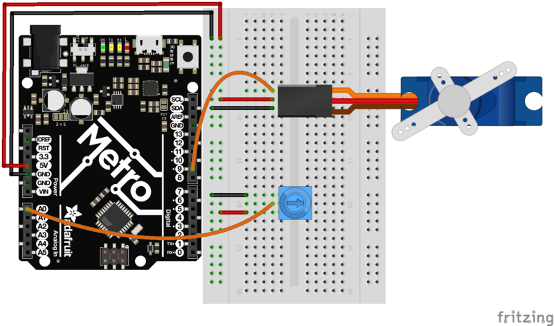
然后打开示例程序旋钮(文件》示例》伺服》旋钮)。上传到您的麦德龙(METRO),然后在转动电位计时观察伺服轴的转动。
CIRC09:浅色
尽管从电位计获取输入对于人体控制实验很有用,但是当我们要进行环境控制实验时我们应该使用什么呢?
我们使用完全相同的原理,但没有使用电位计(基于扭力的电阻),使用光敏电阻(基于光的电阻)。 Metrocan无法直接感应电阻(感应电压),因此我们设置了一个分压器。感测引脚上的确切电压是可以计算的,但出于我们的目的(仅感测相对光),我们可以尝试使用这些值并查看对我们有用的值。当传感器光线充足,而在黑暗中则会产生较高的值。
零件
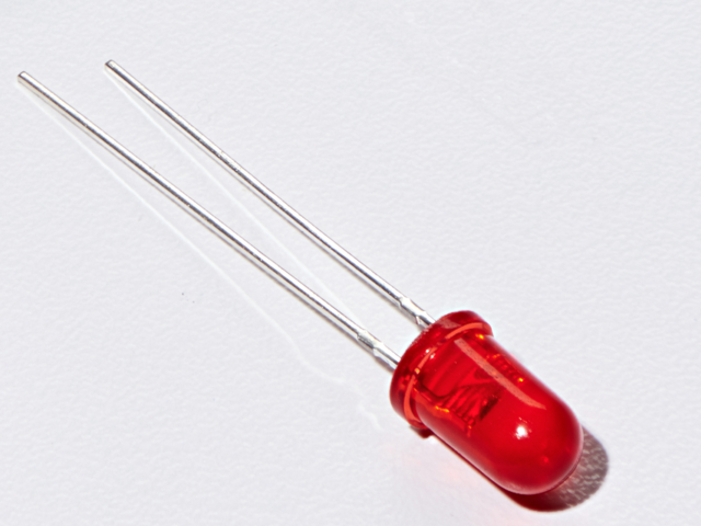
5毫米红色LED
如果您想从Adafruit商店订购更多红色LED(它们可以很好地显示指示灯!),请点击此处!
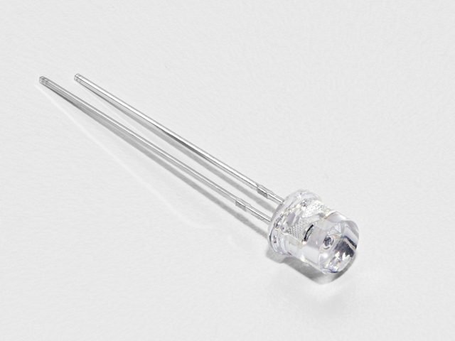
照片传感器
如果您想从Adafruit商店订购其他光敏电阻,请单击此处!
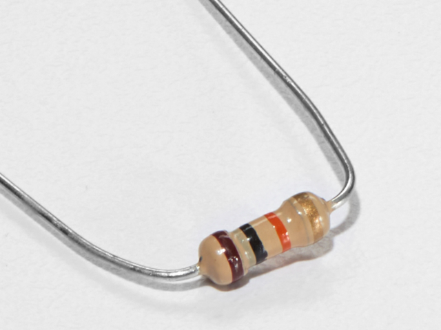
10K欧姆电阻
颜色:棕色》黑色》橙色
如果您想从Adafr订购更多的10k欧姆上拉电阻uit shop,请点击这里!
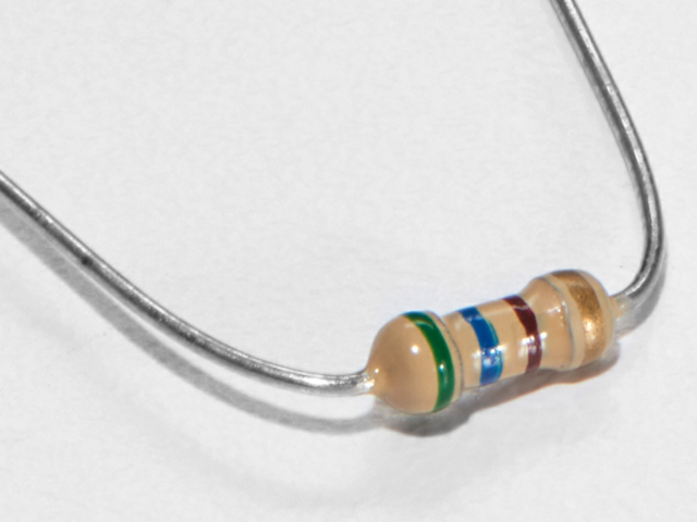
560欧姆电阻
颜色: 绿色》蓝色》棕色
如果您想在Adafruit商店订购更多电阻,请单击此处! (它们的电阻为470欧姆,但可以用)
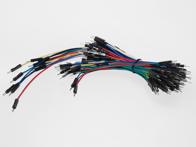
面包板接线束
如果您想从Adafruit商店订购更多电线,请单击此处!
Adafruit Metro(或Metro Express)+面包板+安装板
如果您尚未组装,我们将为您提供方便的指南!
如果d想从Adafruit商店订购额外的塑料安装板,Adafruit Metro,AdafruitMetro Express或Mini-Breadboard,请点击此处!
接线
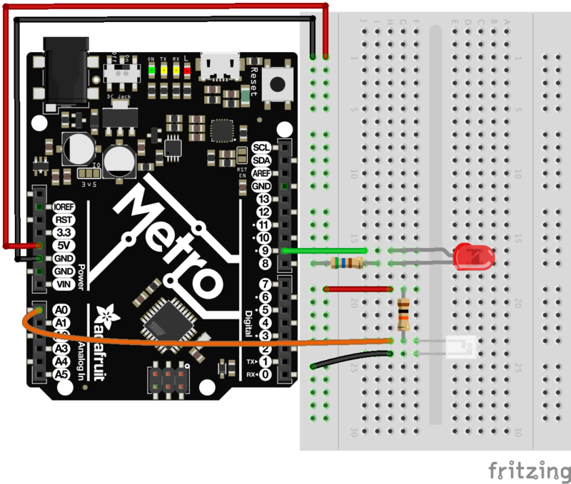
将LED:阳极连接到引脚9 。阴极连接到560欧姆电阻,然后接地。
连接光敏电阻。将10k欧姆电阻的一端连接到电源轨。将其另一端连接到A0,然后将其连接到光敏电阻的一端。电阻的另一端应接地。
可打印的面包板布局表
单击此处下载适用于CIRC09的可打印的面包板布局表
Metro Express的接线
如果您使用的是Adafruit Metro Express,则应使用以下接线。如果您不确定自己拥有什么板,请检查此页面。
面包板上的电源轨应连接到Metro Express上的3.3V引脚
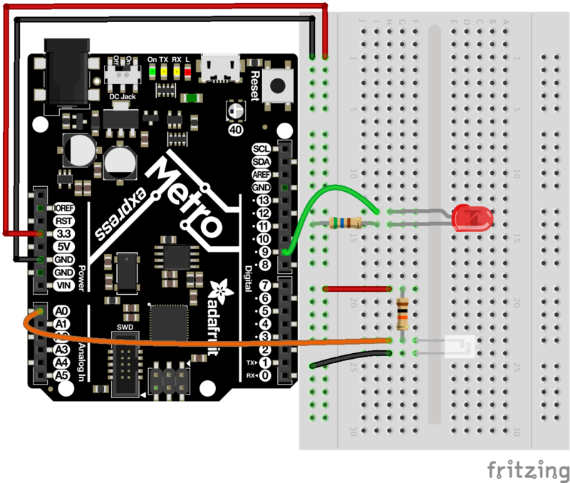
代码
将以下代码复制并粘贴到新的Arduino草图中。然后,编译并将其上传到您的Metro。
下载:Project Zip 或CIRC09_LIGHT.ino | 在Github上查看
复制代码
// CIRC09 - Light
int lightPin = A0;
int ledPin = 9;
void setup()
{
pinMode(ledPin, OUTPUT);
}
void loop()
{
int lightLevel = analogRead(lightPin);
lightLevel = map(lightLevel, 0, 700, 0, 255);
analogWrite(ledPin, lightLevel);
}
// CIRC09 - Light
int lightPin = A0;
int ledPin = 9;
void setup()
{
pinMode(ledPin, OUTPUT);
}
void loop()
{
int lightLevel = analogRead(lightPin);
lightLevel = map(lightLevel, 0, 700, 0, 255);
analogWrite(ledPin, lightLevel);
}
不起作用?
如果光电传感器出现问题:将其翻转,方向可能是
LED保持黑暗
这是一个错误,如果他们只能制造出可以双向工作的LED,我们就会不断地犯错。
它不响应光照变化。
鉴于光敏电阻上导线的间距不是标准的,因此很容易放错位置。仔细检查其正确位置。
仍然不能正常工作吗?
您所在的房间可能太亮或太暗。尝试打开或关闭灯,看看是否有帮助。或者,如果您附近有手电筒,请尝试一下。
变得更好
反转响应
也许您想要相反的响应。不用担心,只要更改即可,我们就可以轻松逆转此响应:
analogWrite(ledPin, lightLevel);-》 analogWrite(ledPin, 255 - lightLevel);
上传修改后的草图并观察响应的变化。
与其控制LED响应光线的亮度,不如根据阈值打开或关闭它。使用以下命令更改 loop()代码:
下载:文件
复制代码
void loop(){
int threshold = 300;
if(analogRead(lightPin) 》 threshold){
digitalWrite(ledPin, HIGH);
}
else{
digitalWrite(ledPin, LOW);
}
} void loop(){
int threshold = 300;
if(analogRead(lightPin) 》 threshold){
digitalWrite(ledPin, HIGH);
}
else{
digitalWrite(ledPin, LOW);
}
}
光控伺服器
此电路使用Metro和Metro Express使用相同的布线。确保将电源轨插入3V而不是5V。
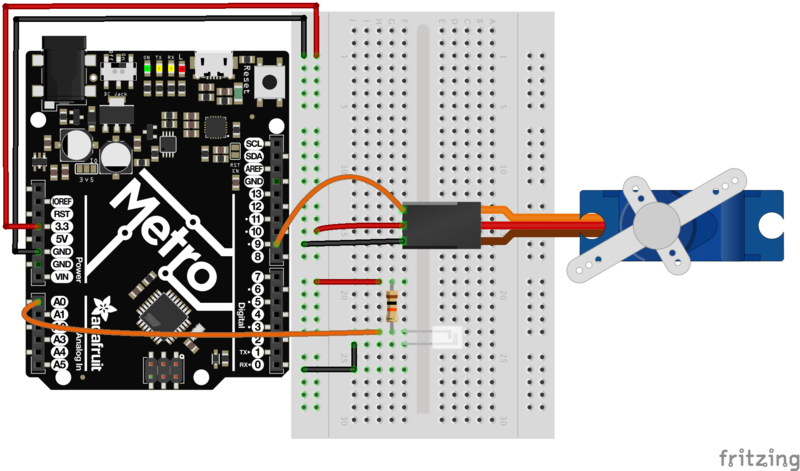
让我们使用我们新发现的光感应技能来控制伺服器(同时进行一些Arduino代码黑客攻击)。连接连接到引脚9的伺服器(如在CIRC-04中)。然后打开旋钮示例程序(与我们在CIRC-08中使用的程序相同)文件》示例》 Library-Servo》旋钮。将代码上传到您的电路板上,并观察其未修改的工作原理。
使用伺服的全部范围
您会注意到,伺服将仅在其范围的有限范围内运行。这是因为在分压电路中,我们使用模拟引脚0上的电压范围不是0至5伏,而是介于两个较小的值之间(这些值将根据您的设置而变化)。要解决此问题,请使用以下行:val = map(val, 0, 1023, 0, 179);(有关操作的提示,请单击此处)
了解更多!
如果您想了解光电传感器背后的魔力,我们有一个学习指南,详细说明该主题
CIRC10:温度
我们将用Metro衡量的下一个现象是什么? 温度。
为此,我们将使用隐藏在与P2N2222AG晶体管 TMP36 相同的封装中的相当复杂的IC(集成电路) 。它具有三个引脚,接地,信号和电源。并且易于使用。
它在信号引脚上每摄氏度输出10毫伏(为了测量冰点以下的温度,偏移量为500 mV,例如25摄氏度= 750 mV,0摄氏度= 500mV)。要将其从数字值转换为度,我们将使用Arduino的一些数学功能。然后要显示它,我们将使用IDE的功能之一,即调试窗口。我们将通过串行连接输出该值以在屏幕上显示。让我们开始吧。
另外一点,该电路使用Arduino IDE的串行监视器。要打开它,首先上传程序,然后单击看起来像带有天线的正方形的按钮。
零件
模拟温度传感器看起来很像NPN晶体管,确保上面显示“ TMP36”!
我是使用NPN 晶体管还是TMP36 温度传感器?
Adafruit Metro(或Metro Express)+面包板+安装板
如果您尚未组装,我们将为您提供方便指南!
如果您想从Adafruit商店订购额外的塑料安装板,Adafruit Metro,AdafruitMetro Express或Mini-Breadboard,请点击此处!
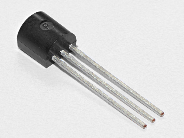
模拟温度传感器
如果您想要一个额外的温度传感器,可以从Adafruit商店购买一个,请点击此处
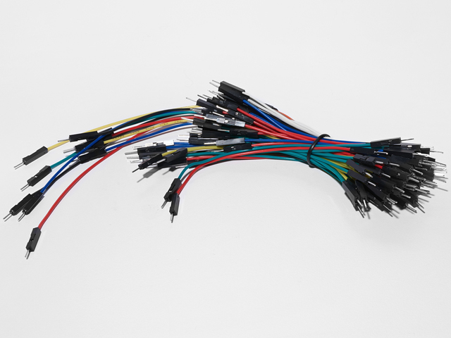
面包板接线束
I如果您想从Adafruit商店订购更多电线,请点击此处!
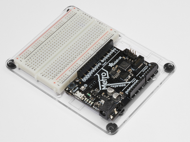
接线
请注意温度传感器的引脚排列。接线错误会迅速加热。
i》
连接
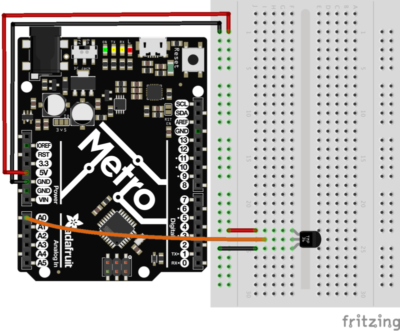
可打印的面包板表
单击此处下载适用于CIRC10的可打印的面包板布局表
Metro Express的接线
如果您使用的是Adafruit Metro Express,则应使用以下接线。如果您不确定自己拥有什么板,请检查此页面。
面包板上的电源轨应连接到Metro Express上的3.3V引脚
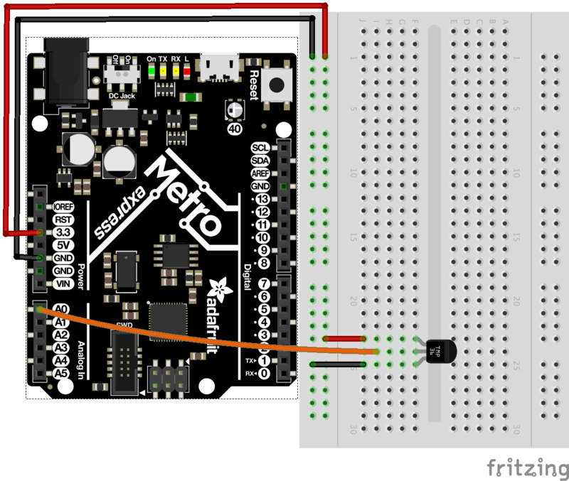
代码
复制/粘贴以下代码。
然后编译并将其上传到您的Metro。
下载:Project Zip 或 CIRC10_TEMPERATURE.ino | 在Github上查看
复制代码
/*
* CIRC10: Temperature
* for use with both the Metro and Metro Express
*
* by Brent Rubell for Adafruit Industries. Support Open Source, buy Adafruit!
*/
#define ANALOGREFVOLTAGE 5.555
//TMP36 Pin
int temperaturePin = A0;
void setup() {
// Start the Serial connection
Serial.begin(9600);
}
void loop() {
float temperature = 0;
temperature = getVoltage(temperaturePin);
Serial.println(temperature);
// Convert to degrees C
temperature = (temperature - .5) * 100;
Serial.println(temperature);
delay(1000);
}
float getVoltage(int pin) {
return(float(analogRead(pin))* float(ANALOGREFVOLTAGE/1023.000));
}
使用Arduino串行监视器
单击Arduino IDE工具栏上的放大镜图标。您应该会看到串行监视器弹出并开始打印数字。
不起作用?
似乎没有发生
此程序没有向外的指示,表明它正在运行。要查看结果,您必须打开Arduino IDE的串行监视器。
显示乱码
之所以会发生这种情况,是因为串行监视器以不同于预期的速度接收数据。要解决此问题,请单击显示为“ *** baud”的下拉框,并将其更改为“ 9600 baud”。
温度值不变
尝试用手指捏住传感器以加热它或按一袋在上面放冰以使其冷却。
变得更好
输出电压
这是更改一个行的简单问题。我们的传感器每摄氏度输出10mv,因此要获取电压,我们只需显示getVoltage()的结果。删除该行:
temperature = (temperature - .5) * 100;
输出华氏度
同样,这是一个简单的更改,仅需数学即可。要达到摄氏度C -》 F,我们使用公式:
(F = C * 1.8)+ 32)
添加以下行:
temperature = (((temperature - .5) * 100)*1.8) + 32; 在Serial.println(temperature);
更多信息输出
让我们在串行输出中添加一条消息,使内容变为出现在“串行监视器”中的信息更丰富。
为此,请更改以下行:
Serial.println(temperature);
至:
Serial.print(temperature);
然后,我们在另一行上添加另一行包含有关温度的信息的文本:
Serial.println(“ degrees centigrade”);
更改为第一行意味着下次输出时,它会显示在同一行上。
更改串行速度
如果您希望在串行线路时间内输出大量数据,本质。目前,我们以9600波特的速度传输信号,但可能会有更快的传输速度。
要更改此更改,请更改线路:
Serial.begin(9600);
到:
Serial.begin(115200);
上传草图,请打开串行监视器,然后在下拉菜单中将速度从9600波特更改为115200波特。现在,您的数据传输速度快了12倍。
CIRC10.5:温度警报
CIRC10 仅在连接到串行监视器时起作用。让我们将电路板从电线上解放出来,制作一个独立式电路!
这是一个 bonus 电路!
使用9V电池运行Metro Express
,我们将制作一个独立的警报来警告我们。
9V电池夹是实验工具包中随附的零件之一。
如果您有9V电池,请将其卡入电池夹中,然后将其插入电池盒的插孔中。地铁:
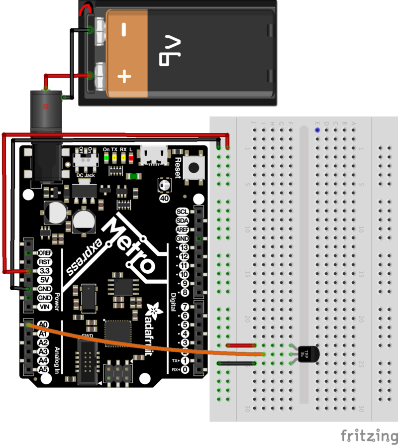
我们的温度传感器现在用9V电池供电。这太棒了,但是我们仍然没有办法警告温度太高/太冷。
添加压电!
Piezo元素是在CIRC06中首次引入的。您将其发送为数字输出,并且蜂鸣。下一步是当压电超过一定温度时会发出嗡嗡声。只需对电路进行最少的修改,即可将压电体用作警报器:
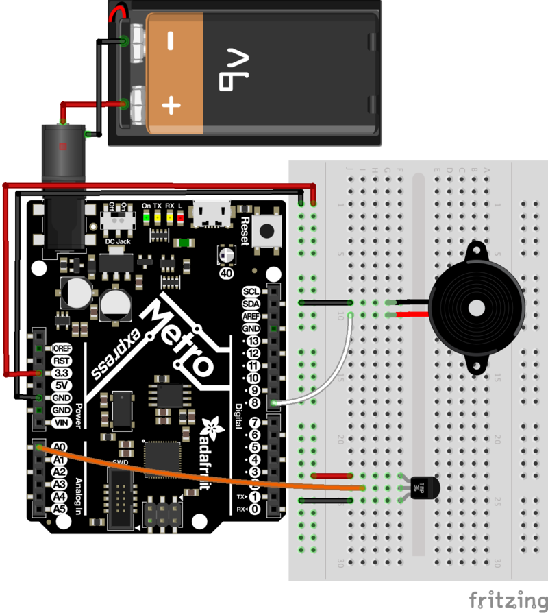
温度警报的代码如下(将其复制并粘贴到空白的Arduino草图中),编译并将其上传到您的Metro:
下载:Project Zip 或 CIRC10_5_TEMP_ALARM.ino | 在Github上查看
复制代码
/* CIRC10.5: Temperature Alarm
* (a bonus circuit for MetroX)
*
* by Brent Rubell for Adafruit Industries
*/
#define ANALOGREFVOLTAGE 5.555
// TMP36 Pin
int temperaturePin = A0;
// Piezo Pin
int piezoPin = 8;
// Freezing
float freezeTemp = 0;
// Boiling
float boilTemp = 26;
void setup()
{
// Start the Serial connection
Serial.begin(9600);
}
void loop()
{
float temperature = 0;
temperature = getVoltage(temperaturePin);
// Convert to degrees C
temperature = (temperature - .5) * 100;
Serial.println(temperature);
if(temperature 《 freezeTemp) {
tone(piezoPin, 1100, 1000);
}
else if(temperature 》 boilTemp) {
tone(piezoPin, 1100, 1000);
}
delay(1000);
}
float getVoltage(int pin) {
return(float(analogRead(pin))* float(ANALOGREFVOLTAGE/1023.000));
}
更改变量
我们在摄氏温度中预定义了冻结和沸腾变量,但是如果您要使用华氏度(或kelvinjust,请将下面的变量更改为其他值:
float freezeTemp = 0;
float boilTemp = 26;
CIRC11:继电器的负载更大
下一个电路有点挑战。我们结合了在CIRC03中使用晶体管来控制继电器的知识。
继电器是一种电控机械开关。小塑料盒内有一个电磁体,当通电时,该电磁体会使开关跳闸(通常会发出非常令人满意的咔嗒声)。您可以购买大小不等的继电器,该继电器的大小从套件中的四分之一到冰箱一样大,每个继电器都可以切换一定量的电流。它们非常有趣,因为它们具有某种物理元素。
虽然到目前为止我们玩过的所有芯片有时都很有趣,但是您可能只想连接一百个开关来控制宏伟的东西。继电器使您能够幻想它,然后使用Arduino控制它。现在,运用当今的技术来控制过去。 (1N4001二极管用作反激二极管,请单击此处以获取有关反激二极管的更多信息)
零件
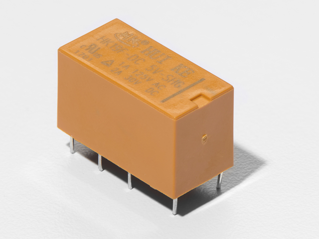
DPDT中继
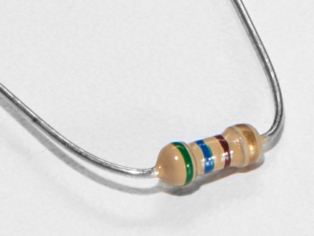
560欧姆电阻
QTY:x2
颜色:绿色》蓝色》棕色
如果您想从Adafruit商店订购更多电阻,请单击此处! (它们的电阻为470欧姆,但可以用)
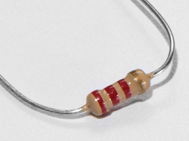
2.2k欧姆电阻
颜色:红色》红色》红色
如果您想从Adafruit商店订购额外的2.2k Ohm电阻器,请单击此处!
此电路使用NPN晶体管,而不是TMP36传感器。
我是使用NPN 晶体管还是TMP36 温度传感器?
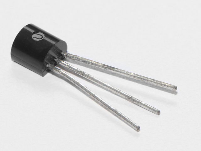
晶体管(PN2222或MPS2222)
如果您想从Adafruit商店订购额外的NPN晶体管,请单击此处!
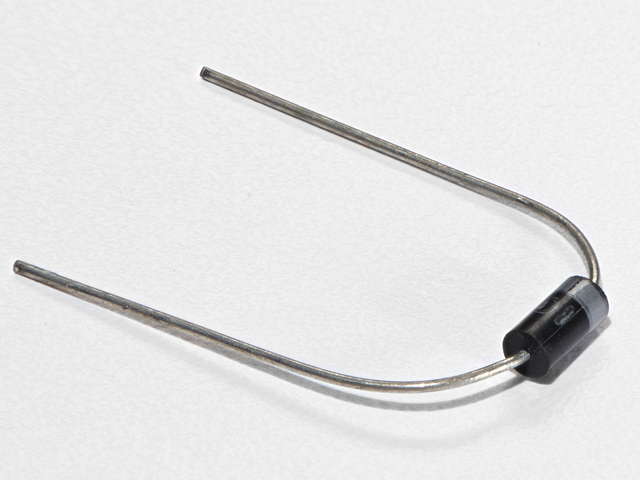
二极管(1N4001)
如果您想在Adafruit商店订购更多二极管,请单击此处!
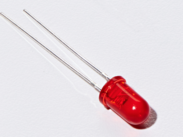
5mm红色LED
如果您愿意从Adafruit商店订购更多的红色LED(它们使指示灯很好!),请单击此处!
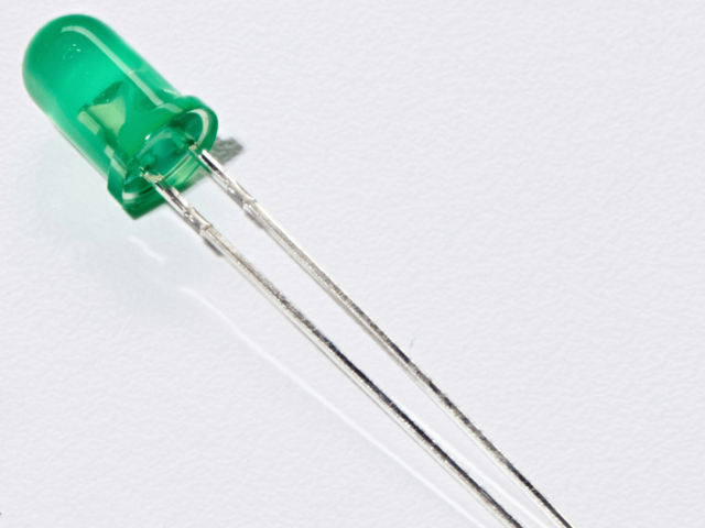
5mm绿色LED
如果您要订购额外的绿色Adafruit的LED商店,请点击此处!
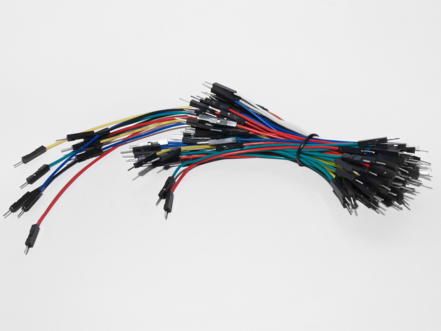
面包板接线束
如果您想从Adafruit商店订购更多电线,请单击此处!
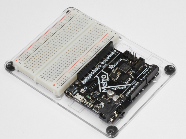
Adafruit Metro(或Metro Express)+面包板+安装板
如果您尚未组装此板,我们将为您提供方便的指南!
如果您要订购额外的塑料安装板,Adafruit Metro,AdafruitMetro Express或Adafruit Shop的迷你面包板请单击此处!
接线
接线:
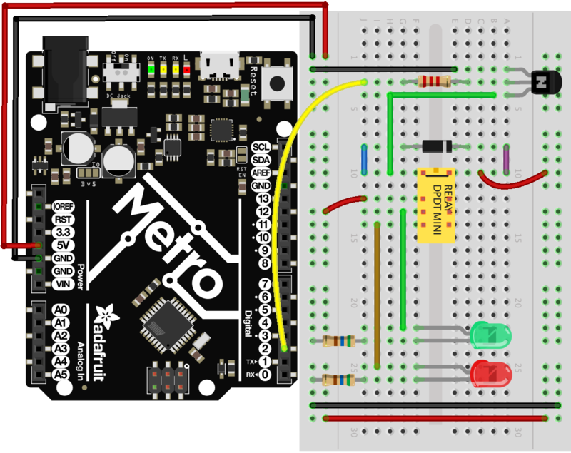
确保晶体管的平坦面朝向地铁。
继电器接线的特写
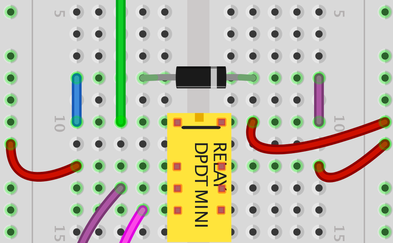
确保 DPDT中继面顶部的小方块面包板的顶部。另外,请确保DPDT继电器的二极管面 右侧上的条纹。
可打印面包板布局表
点击此处下载适用于CIRC11的可打印面包板布局表
代码
将下面的代码复制并粘贴到空白的Arduino草图中。然后编译并将其上传到您的Metro。
下载:Project Zip 或 CIRC11_RELAY.ino | 在Github上查看
复制代码
// CIRC11 - Relay
int relayPin = 2;
void setup() {
pinMode(relayPin, OUTPUT);
}
void loop() {
digitalWrite(relayPin, HIGH);
delay(1000);
digitalWrite(relayPin, LOW);
delay(1000);
}
// CIRC11 - Relay
int relayPin = 2;
void setup() {
pinMode(relayPin, OUTPUT);
}
void loop() {
digitalWrite(relayPin, HIGH);
delay(1000);
digitalWrite(relayPin, LOW);
delay(1000);
}
不起作用?
什么都没发生
示例代码使用了第13针,我们将继电器连接到引脚2。请确保您在代码中做了以下更改:
LED_BUILTIN -》 2
没有点击声音
电路的晶体管或线圈部分无法正常工作。检查晶体管是否正确插入。
效果不佳或无法正常工作
随附的继电器设计为焊接而不是在面包板上使用。因此,您可能需要按入以确保其正常工作(并且有时会弹出)。
变得更好
反电动势脉冲
用LED替换二极管。您会看到它每次“吸收”线圈电压尖峰时都会闪烁。关闭。
控制电机
在CIRC-03中,我们使用晶体管控制了电动机。但是,如果要控制更大的电动机,则继电器是一个不错的选择。为此,只需卸下红色LED并将电动机连接到位即可。
控制电动机方向
需要完成一些复杂的改进。为了控制直流电动机的旋转方向,我们必须能够使流过直流电动机的电流方向反向。要手动执行此操作,我们需要反转引线。要进行电操作,我们需要一种称为h桥的东西。这可以通过使用DPDT继电器来控制电动机的方向来完成,并连接以下电路。它看起来很复杂,但仅需使用几根额外的导线即可完成。尝试一下。
示意图布局
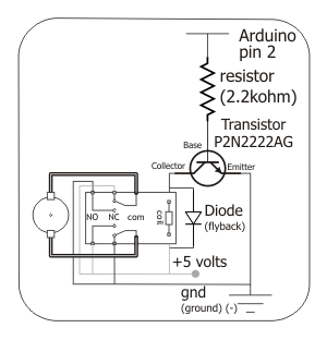
面包板布局
CIRC12:七彩光芒
我们使一个LED闪烁并按顺序控制8个。现在该控制颜色了。使用RGB LED(单个外壳中实际上有3个LED),我们可以产生我们内心想要的任何颜色。
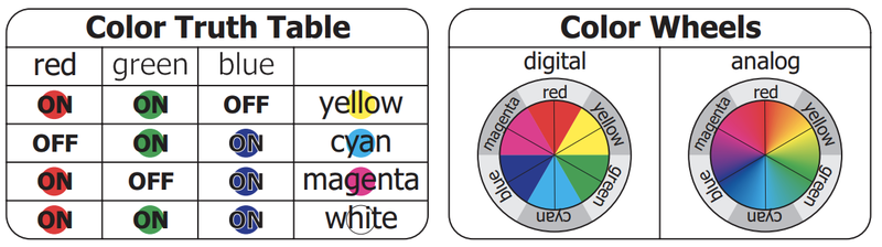
我们通过颜色混合来做到这一点,需要的是深入研究使用彩色玻璃纸以产生不同颜色的基础艺术时代(如果您不记得很久了,请不要担心,这里有一个色轮可以帮助您)。
零件
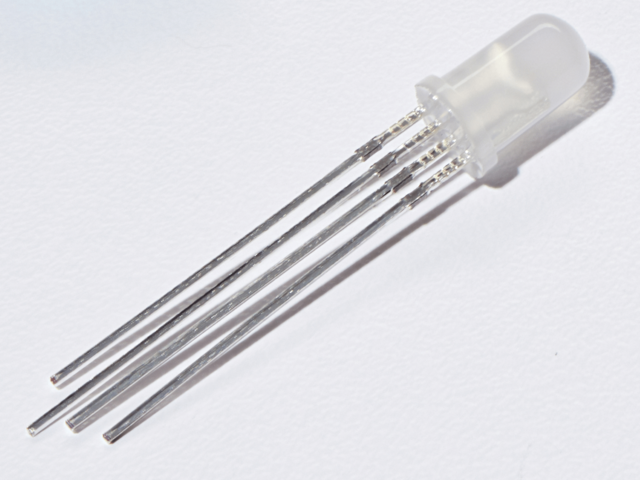
RGB LED
如果您想从Adafruit商店购买另一个RGB LED,请单击此处。
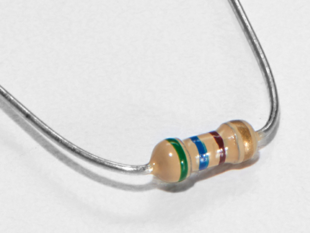
560欧姆电阻 》
数量:x3
颜色: 绿色》蓝色》棕色
如果您想从Adafruit商店订购更多电阻,请点击此处! (它们的电阻为470欧姆,但可以用)
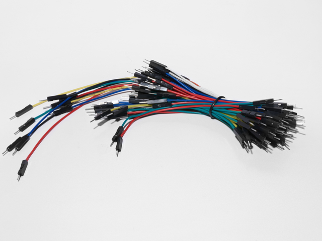
面包板接线束
如果您想从Adafruit商店订购更多电线,请单击此处!

Adafruit Metro(或Metro Express)+面包板+安装板
如果您尚未组装,我们将为您提供方便的指南!
如果d想从Adafruit商店订购额外的塑料安装板,Adafruit Metro,AdafruitMetro Express或Mini-Breadboard,请点击此处!
接线
下方:
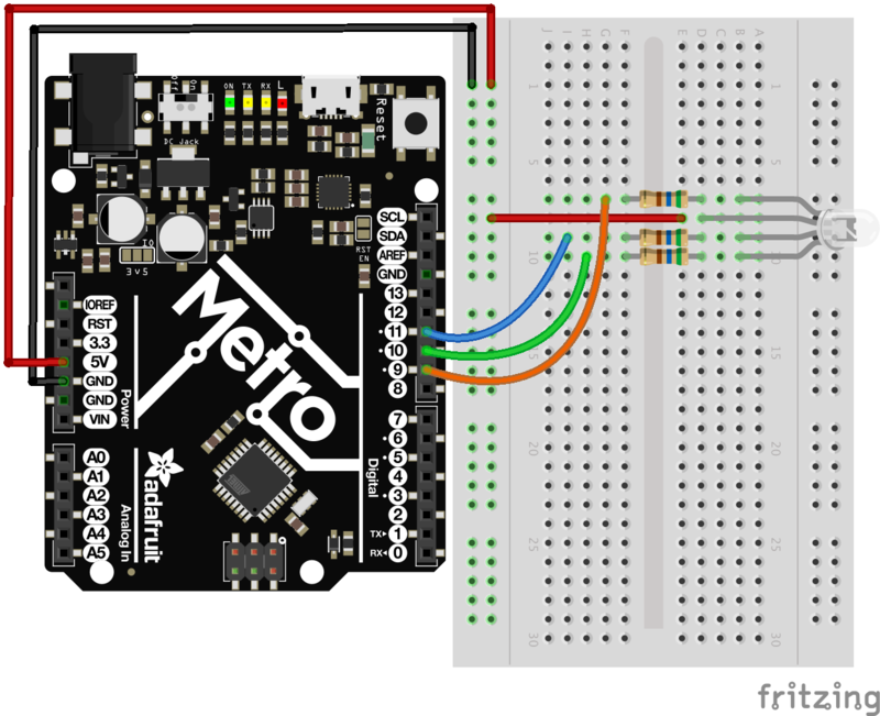
将第一个RGB LED支路连接到560欧姆电阻,然后引脚9
将第二个RGB LED支路连接到560欧姆电阻,然后引脚10
将第一个RGB LED支路连接到560欧姆电阻,然后引脚11
请注意, RGB LED的strong》最长的脚连接到电源轨5V。
可打印的面包板布局表
单击此处下载用于CIRC12的可打印的面包板布局表
Metro Express的接线
如果您使用的是Adafruit Metro Express,则应使用以下接线。如果您不确定自己拥有什么板,请检查此页面。
面包板上的电源轨应连接到Metro Express上的3.3V引脚
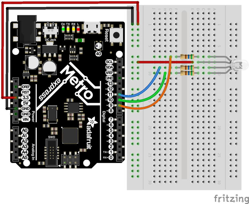
代码
将下面的代码复制并粘贴到空白的Arduino草图中。然后编译并将其上传到您的Metro。
下载:Project Zip 或 CIRC12_RGB_LED.ino | 在Github上查看
复制代码
// CIRC12 - RGB LED
// RGB LED PINS
// three pins:
// 9 = RED
// 10 = GREEN
// 11 = BLUE
int ledDigitalOne[] = {9, 10, 11};
// define on as low
// (because you use a common anode RGB LED)
const boolean ON = LOW;
// define off as high
const boolean OFF = HIGH;
// Predefined Colors
const boolean RED[] = {ON, OFF, OFF};
const boolean GREEN[] = {OFF, ON, OFF};
const boolean BLUE[] = {OFF, OFF, ON};
const boolean YELLOW[] = {ON, ON, OFF};
const boolean CYAN[] = {OFF, ON, ON};
const boolean MAGENTA[] = {ON, OFF, ON};
const boolean WHITE[] = {ON, ON, ON};
const boolean BLACK[] = {OFF, OFF, OFF};
//An Array that stores the predefined colors
const boolean* COLORS[] =
{RED, GREEN, BLUE,YELLOW, CYAN, MAGENTA,
WHITE, BLACK};
void setup() {
for(int i = 0; i 《 3; i++){
// set the 3 pins as outputs
pinMode(ledDigitalOne[i], OUTPUT);
}
}
void loop() {
// set the color of the LED
setColor(ledDigitalOne, CYAN);
// randomize it
// randomColor();
}
void randomColor(){
// get random number within range of colors
int rand = random(0, sizeof(COLORS) / 2);
setColor(ledDigitalOne, COLORS[rand]);
delay(1000);
}
void setColor(int* led, const boolean* color) {
for(int i = 0; i 《 3; i++){
digitalWrite(led[i], color[i]);
}
}
有问题吗?
LED保持暗或显示不正确的颜色
使用四个插针LED如此紧密地结合在一起,有时很容易将其放错位置。尝试仔细检查每个插针的位置。
绿色和蓝色似乎相反
某些RGB LED交换了绿色和蓝色,更改您的代码,以便交换引脚并重新上传!
看到红色
红色RGB LED中的二极管可能比其他两个二极管亮一些。要使颜色更平衡,请尝试使用较高的电阻器(或两个串联的电阻器)。
正在寻找更多内容?
如果您想做更多的事情,为什么不检查一下可从中获得的所有可爱的额外内容和鲍勃Adafruit商店。
变得更好
更多颜色
我想在您之前,您对蓝绿色发光的LED印象不那么深刻。要显示其他颜色,请将代码中的颜色更改为其他颜色之一:
setColor(ledDigitalOne, CYAN);-》 setColor(ledDigitalOne, newColor)
》
显示随机颜色
当然我们除了显示恒定的颜色外,还可以做更多的事情。若要查看如何在随机颜色之间循环,请将loop()代码更改为:
下载:文件
复制代码
void loop() {
//setColor(ledDigitalOne, CYAN);
randomColor();
} void loop() {
//setColor(ledDigitalOne, CYAN);
randomColor();
}
模拟色彩控制
虽然在颜色之间进行切换很有趣,但当将RGB LED与模拟控制。使用PWM(脉冲宽度调制),几乎可以产生任何颜色并在它们之间褪色。遗憾的是,对于上面的部分,此代码太长了,因此请单击下面的代码以查看该代码:
模拟色彩控制代码
CIRC13:压缩
力敏电阻(FSR)是使您能够检测施加在其上的压力的传感器。它们类似于电位计(例如在CIRC08中),除了通过扭力来改变电阻外,FSR的电阻会随着压力而变化。
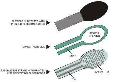
FSR由2个由隔离层分隔的层组成。按下的次数越多,有源元件上与半导体接触的点就越多,这会使电阻降低。它们不适用于检测精确的重量,但对检测挤压,推挤和戳戳非常有用。如果您想更深入地研究FSR的工作原理,ladyada有很好的学习指南,其中涵盖了更多的技术细节。
零件
5毫米绿色LED
如果您要订购更多的绿色LED,请从Adafruit商店,请单击此处!
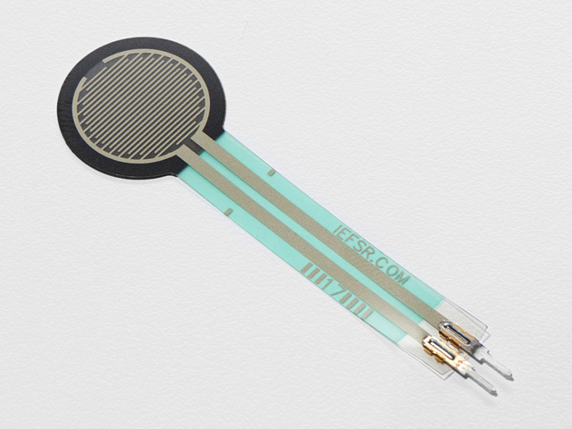
力敏感电阻器
如果要从Adafruit商店订购力敏感电阻器,请单击此处!
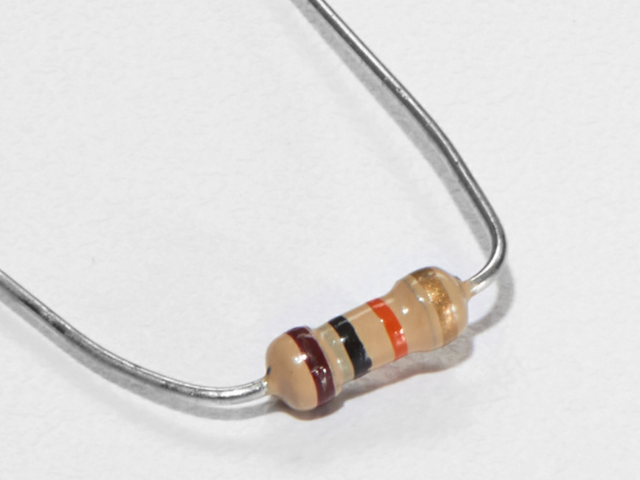
10K欧姆电阻
颜色:棕色》黑色》橙色
如果您要订购更多的10k ohm上拉电阻Adafruit商店的电阻器,请单击此处!
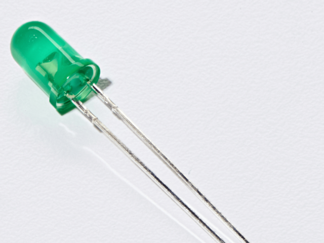
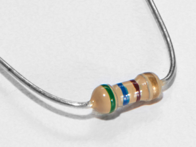
560欧姆电阻
颜色: 绿色》蓝色》棕色
如果您想从Adafruit商店订购更多电阻器,请单击此处! (它们的电阻为470欧姆,但可以用)
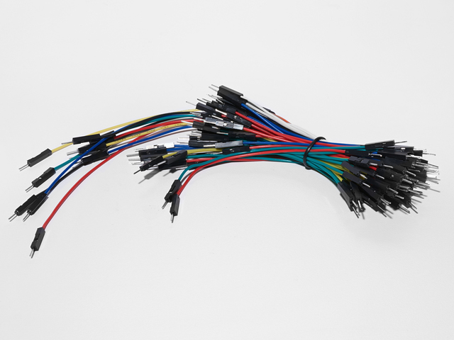
面包板接线束
如果您想从Adafruit商店订购更多电线,请单击此处!
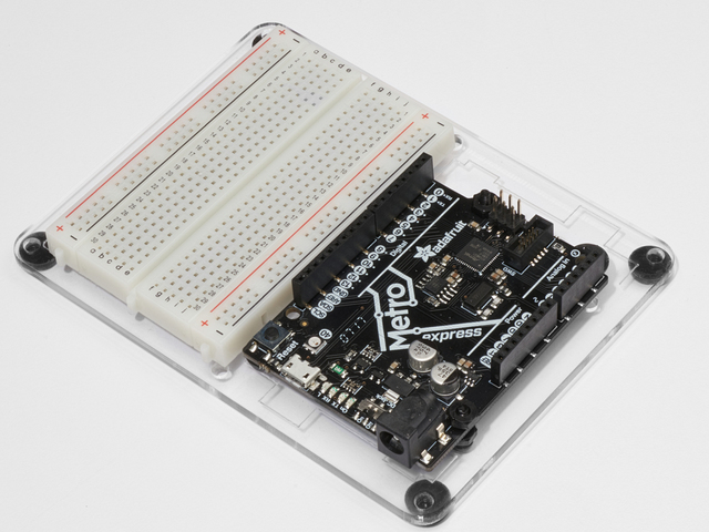
Adafruit Metro(或Metro Express)+面包板+安装板
如果您尚未组装,我们将为您提供方便的指南!
如果d想从Adafruit商店订购额外的塑料安装板,Adafruit Metro,AdafruitMetro Express或Mini-Breadboard,请点击此处!
布线
该电路的布线对于地铁和地铁快递。请注意,电源轨连接到3V而不是5V。
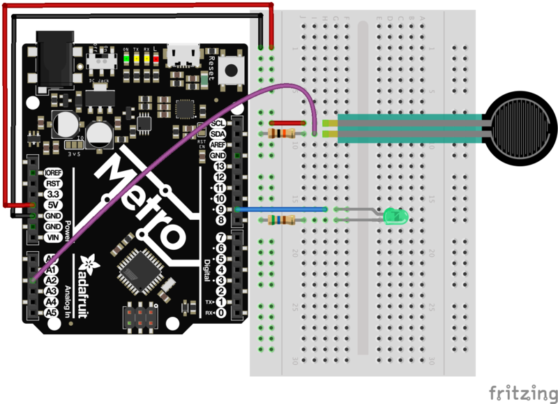
最后一个电路易于构建,但使用起来确实很有趣:
力敏电阻的一端( FSR)连接到电源轨。
FSR的另一端连接到模拟引脚2 和一个10k欧姆上拉电阻。
连接一个红色的LED指示灯连接到引脚9 和一个560欧姆的限流电阻。
可打印的面包板布局表
点击此处下载适用于CIRC13的可打印的面包板布局表
代码
将下面的代码复制并粘贴到空白的Arduino草图中。然后编译并将其上传到您的Metro。
下载:Project Zip 或 CIRC13_FSR.ino | 在Github上查看
复制代码
/*
* Force Sensitive Resistor Test Code
*
* The intensity of the LED will vary with the amount of pressure on the sensor
*/
int sensePin = 2; // the pin the FSR is attached to
int ledPin = 9; // the pin the LED is attached to (use one capable of PWM)
void setup() {
Serial.begin(9600);
pinMode(ledPin, OUTPUT); // declare the ledPin as an OUTPUT
}
void loop() {
int value = analogRead(sensePin) / 4; //the voltage on the pin divded by 4 (to
//scale from 10 bits (0-1024) to 8 (0-255)
analogWrite(ledPin, value); //sets the LEDs intensity proportional to
//the pressure on the sensor
Serial.println(value); //print the value to the debug window
}
不起作用?
LED指示灯不亮?
LED只能在一个中工作方向。尝试将其取出并扭曲180度。 (不必担心,向后安装它不会造成永久损害)。
渐变为快/慢
这是FSR对压力的响应不是线性的结果。但是不要担心可以在代码中对其进行更改(请查看“使它变得更好”部分中的详细信息)
正在寻找更多内容?
您很幸运-本指南中有额外的 CIRC 界面和包括了几个 PROJ 项目!查看左侧的侧边栏以获取完整列表。
变得更好
校准范围
虽然光线正在逐渐消失,但其响应可能并不十分完美。要调整响应,我们需要在代码中再增加一行:
map(value, fromLow, fromHigh, toLow, toHigh)
要校准传感器,我们可以像使用CIRC- 11。打开串行监视器,然后在完全按下传感器时将fromLow值替换为值显示。
然后,将fromHigh值替换为未按下的值。
最后,填写范围toLow = 0和toHigh = 255
结果将如下所示:
下载:文件
复制代码
int value = analogRead(sensePin);
map(value, 125, 854, 0, 255);
analogWrite(ledPin, value); int value = analogRead(sensePin);
map(value, 125, 854, 0, 255);
analogWrite(ledPin, value);
RGB Strongperson测试
步骤马上通过Adafruit Metro High Striker Game来测试自己的力量!只有最强的人才能成功!让我们使用RGB LED快速修改电路以指示强度级别,并修改代码以显示有人按下力敏电阻的力度。
图:RGB +力电阻器
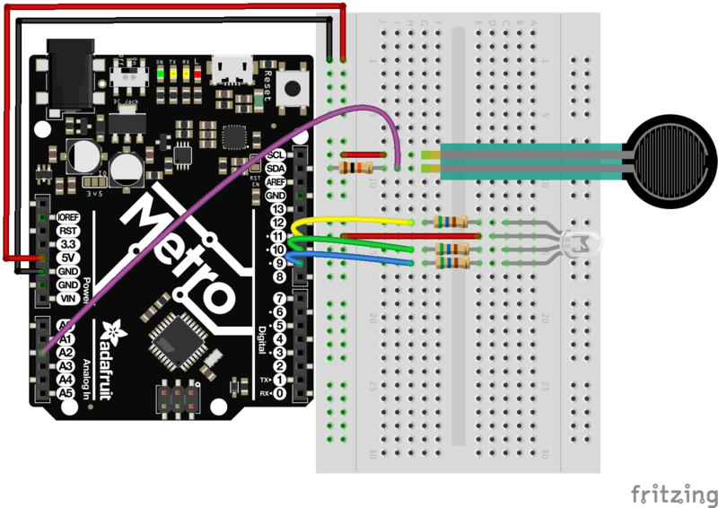
下面的代码将需要首先运行,然后进行修改。运行它后,打开串行监视器,并尽可能用力按力敏电阻。印刷的值是有人可以在电路上按下FSR的maxForce。将maxForce设置为串行监视器中的值:
// set maxForce
int maxForce = FORCEVALUE;
设置了maxForce之后,祝您好运!我们提供了一个串行打印输出,以显示您压下FSR的程度。
下载:file
复制代码
/*
FSR Strongperson Test for Metro (and Metro Express)
Utilizes a FSR and a RGB LED to test how strong you are.
Created 7 July 2017
By Brent Rubell for Adafruit Industries
Support Open Source ~ buy Adafruit
*/
// fsr pin
int sensePin = A2;
// rgb led pins
int rgbLED[] = {9, 10, 11};
// common cathode rgbleds
const boolean ON = LOW;
const boolean OFF = HIGH;
// predefined colors
const boolean BLUE[] = {ON, OFF, OFF};
const boolean RED[] = {OFF, OFF, ON};
const boolean GREEN[] = {OFF, ON, OFF};
void setup() {
Serial.begin(9600);
// set all rgb pins as outputs
for(int i = 0; i《3; i++){
pinMode(rgbLED[i], OUTPUT);
}
}
void loop() {
// scale voltage down to 255 from 1023
int force = analogRead(sensePin) / 4;
// check maximum force by squeezing the FSR
Serial.println(force);
// set maxForce
int maxForce = 160;
// calculate regions
int lowForce = maxForce / 3;
int medForce = (maxForce / 3) * 2;
// check force regions
if(force 《 lowForce) {
Serial.println(“easy”);
setColor(rgbLED, RED);
}
else if (force 》 lowForce && force 《 medForce) {
Serial.println(“medium”);
setColor(rgbLED, BLUE);
}
else {
Serial.println(“hard”);
setColor(rgbLED, GREEN);
}
}
// rgb color mixing
void setColor(int* led, const boolean* color) {
for(int i = 0; i 《 3; i++){
digitalWrite(led[i], color[i]);
}
} /*
FSR Strongperson Test for Metro (and Metro Express)
Utilizes a FSR and a RGB LED to test how strong you are.
Created 7 July 2017
By Brent Rubell for Adafruit Industries
Support Open Source ~ buy Adafruit
*/
// fsr pin
int sensePin = A2;
// rgb led pins
int rgbLED[] = {9, 10, 11};
// common cathode rgbleds
const boolean ON = LOW;
const boolean OFF = HIGH;
// predefined colors
const boolean BLUE[] = {ON, OFF, OFF};
const boolean RED[] = {OFF, OFF, ON};
const boolean GREEN[] = {OFF, ON, OFF};
void setup() {
Serial.begin(9600);
// set all rgb pins as outputs
for(int i = 0; i《3; i++){
pinMode(rgbLED[i], OUTPUT);
}
}
void loop() {
// scale voltage down to 255 from 1023
int force = analogRead(sensePin) / 4;
// check maximum force by squeezing the FSR
Serial.println(force);
// set maxForce
int maxForce = 160;
// calculate regions
int lowForce = maxForce / 3;
int medForce = (maxForce / 3) * 2;
// check force regions
if(force 《 lowForce) {
Serial.println(“easy”);
setColor(rgbLED, RED);
}
else if (force 》 lowForce && force 《 medForce) {
Serial.println(“medium”);
setColor(rgbLED, BLUE);
}
else {
Serial.println(“hard”);
setColor(rgbLED, GREEN);
}
}
// rgb color mixing
void setColor(int* led, const boolean* color) {
for(int i = 0; i 《 3; i++){
digitalWrite(led[i], color[i]);
}
}
其他应用程序
有了传感器,真正的乐趣就在于如何以整洁而出乎意料的方式使用它们。因此,请思考一下感测力如何以及在何处可以改善您的生活(或其他人的生活)。
CIRC14:字符LCD
我们在Adafruit商店中提供了许多不同类型的字符LCD。实验者工具包提供了一种,但如果您还没有,则在实验者指南中使用16x2变体。
字符LCD对于显示文本,数据,可变信息或提供交互界面。您已经在先前的学习指南中使用了串行监视器。虽然从Metro显示数据很有用,但需要通过USB将其绑定到计算机。字符LCD使您可以自由放置任何想要打印的显示-文本,数据甚至小图标(5像素x 7像素)
零件
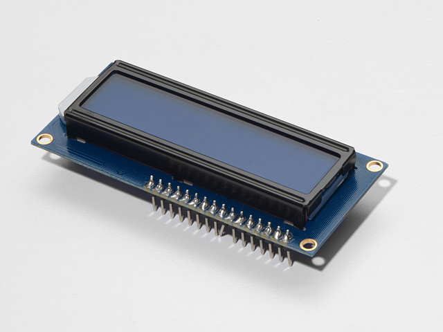
16x2字符LCD
如果您想从Adafruit商店购买蓝白色的16x2字符LCD,请单击此处!
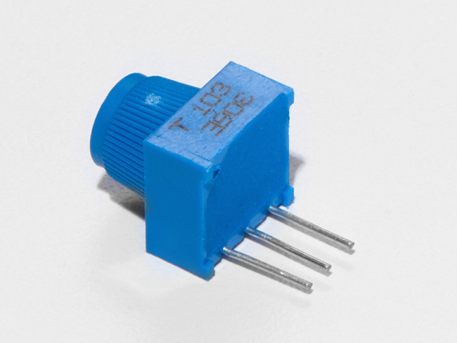
面包板微调电位器-10k
如果您想从Adafruit商店购买一个额外的微调锅,请单击此处!
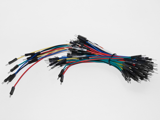
面包板接线束
如果您想从Adafruit商店订购更多电线,请点击此处!
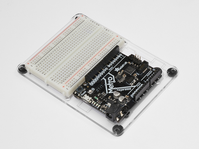
Adafruit Metro(或Metro Express)+面包板+安装板
如果您尚未组装,我们将为您提供方便的指南!
如果您想订购额外的塑料安装板,Adafruit Metro,AdafruitMetro Express或Mini -Adafruit商店的面包板请单击此处!
接线
此页面上的说明和接线基于ladyada出色的字符LCD接线指南,但已针对弗里辛特进行了更新。
组装LCD
某些16x2 LCD可能已经组装好了,这意味着接头已经焊接到了:
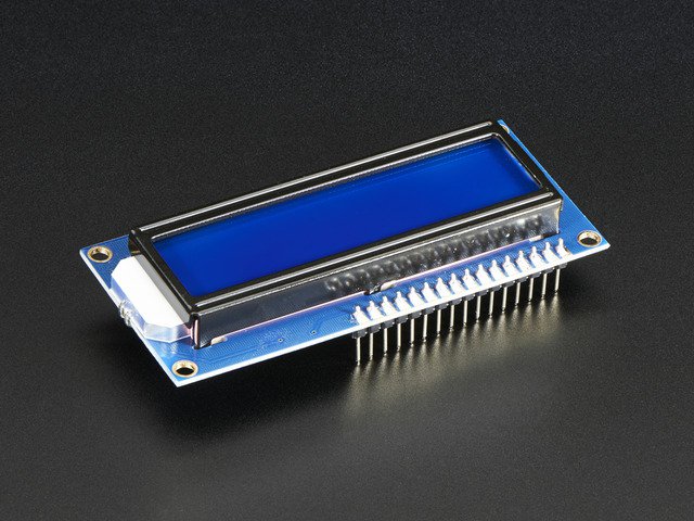
组装好的标准LCD 16x2 +附加功能-蓝底白字
产品ID:1447
标准的HD44780 LCD对于创建独立项目非常有用。此产品类似于我们的标准LCD 16x2显示屏。。.
$ 10.95
入库存
添加到购物车
我们还有一些未组装的带有未焊接头的产品:
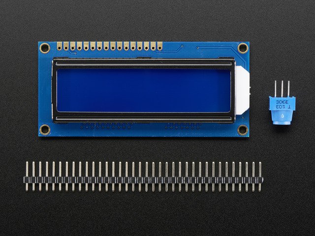
标准LCD 16x2 +其他功能
产品ID:181
标准HD44780 LCD适用于创建独立的项目。16个字符,2行,蓝色背景上的白色文本连接端口为0.1“ 。。.
$ 9.95
库存div》
添加到购物车
如果已组装液晶显示器,则可以跳过以下后续步骤,直接进行操作
div》焊接LCD
焊接在电子领域是一项非常有用的技能。这是将两种金属结合在一起的过程,使用另一种金属(也包括它们之间)。如果您以前从未做过此事,比尔·厄尔(Bill Earl)撰写了一篇很棒的视觉指南,名为《 Adafruit卓越焊接指南》 ,它将使您快速入门。如果您希望观看视频,Collin的实验室也涵盖了焊接工作:
16x2 LCD并不难焊接,但是它确实有很多别针。我们有一些建议像专业人士那样焊接:
首先将16x2 LCD和插头插入面包板。
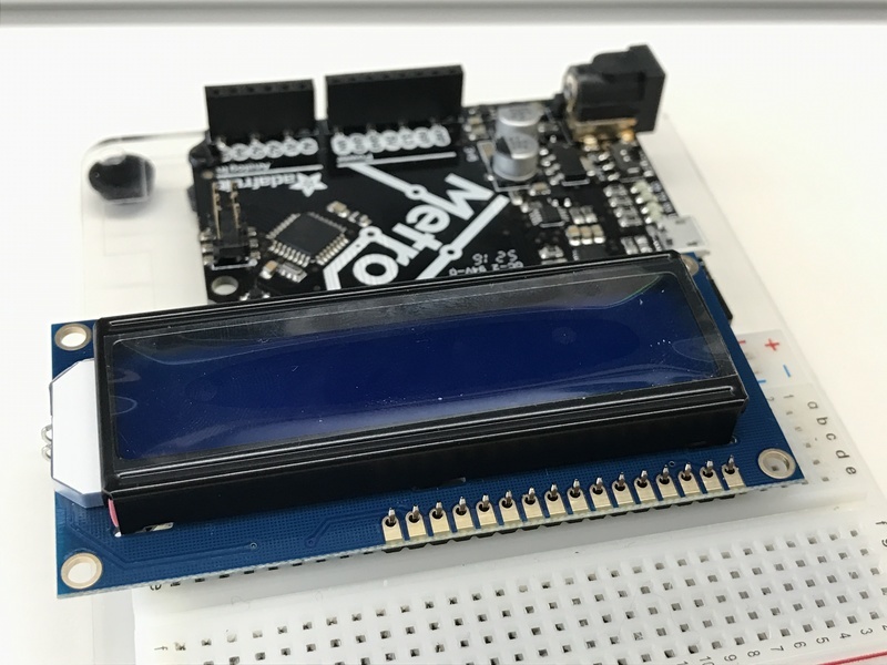
然后,(具有中等热量,不要使熨斗过热!)开始将 Pin 1 焊接到割台。下一个焊锡引脚16。这会将焊锡头“固定”到LCD上,从而焊接其余的引脚焊锡。
现在,将所有焊锡焊接起来其他针脚!
没事吗?您的标头有问题吗?焊接很容易修复。这只需要时间。在继续操作之前,请检查本指南中的错误,并进行更正。
接线和背光
如果这些照片太小,您可以右键单击它们-》“复制图像地址”,然后将该地址粘贴到浏览器的URL栏中以获取完整分辨率的屏幕截图。
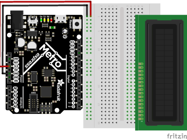
首先,将LCD插入面包板。然后,将 + 5V Pin 连接到电源轨,将 GND Pin 连接到接地轨。
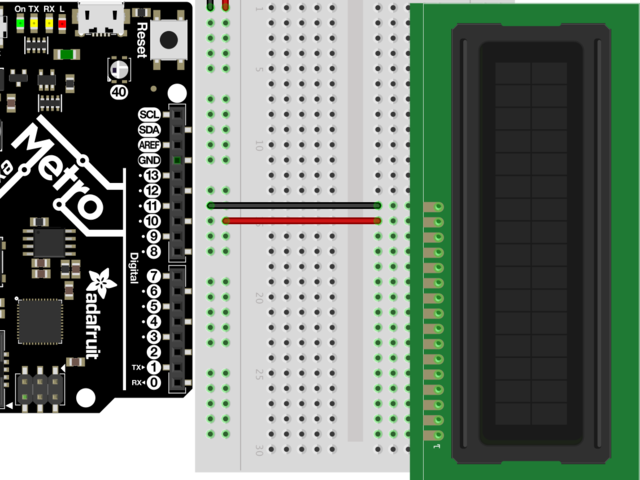
下一步,连接将LCD引脚16 连接到GND导轨,将 LCD引脚15 连接到电源导轨。
在执行电源检查之前不要继续
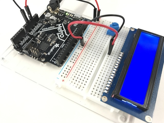
让我们检查一下它的功能。将Metro或Metro Express连接到电源。您应该看到LCD亮起。一些低成本的LCD不带背光。
如果您的LCD带有背光,并且如果您没有看到背光,请返回并检查接线。
布线对比电路
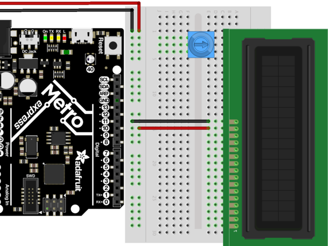
下一步,让我们将对比度电位计放在LCD引脚16的左侧。您可以将其放在面包板上的任何位置一样,但下一个CIRC放置在 LCD Pin 16
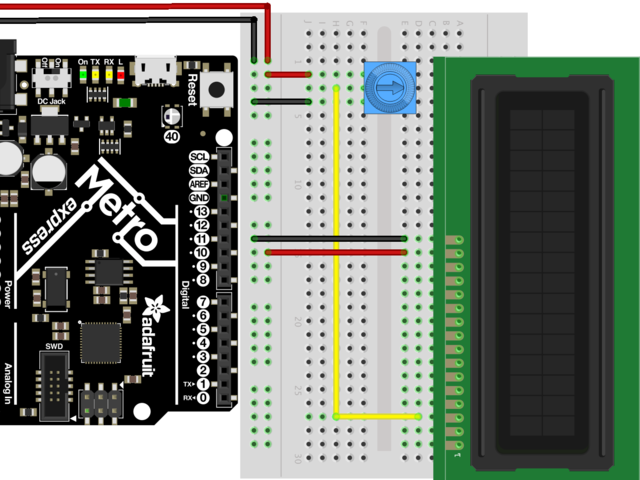
将电位计的外部引脚之一连接到电源导轨。将另一个外部引脚连接到接地导轨。不管走到哪里,只要一个引脚上电并且一个引脚接地,其他引脚就可以互换。
电位器(抽头)的中间连接到 LCD引脚3
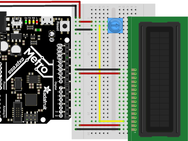
LCD引脚1 连接到接地轨。 LCD引脚2 连接到电源轨。这些引脚是LCD的逻辑。
在通电后看到矩形并且电位计已扭曲之前不要继续移动。
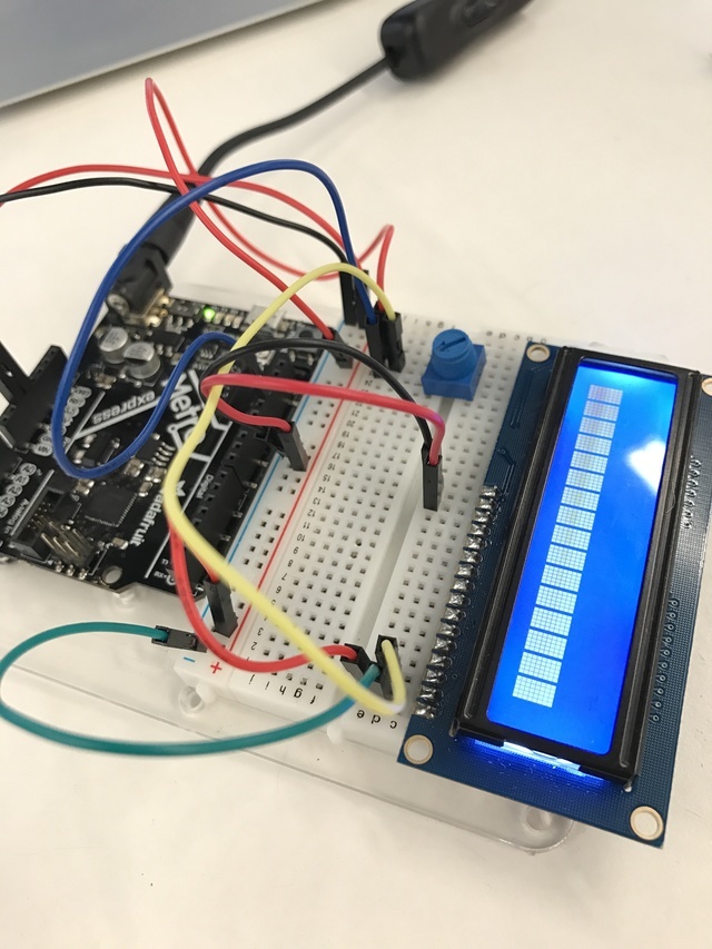
在继续之前,我们将进行一次小测试以确保接线正确。插入Metro或Metro Express并扭转电位计。您应该看到LCD第一行上出现黑色矩形。 如果看不到,请在继续操作之前检查接线。
接线数据总线
接下来,我们将连接 RS引脚。我们使用蓝线将 LCD Pin 4 连接到 Metro Digital Pin 7
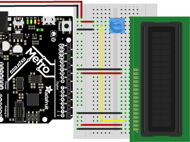
本指南不需要 RW 引脚,因为我们只是在写到显示器。将 LCD引脚5 连接到接地导轨。
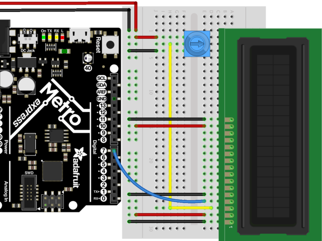
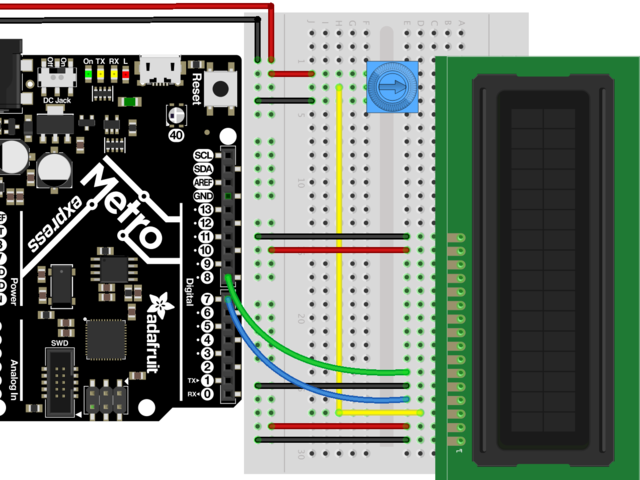
下一步是 EN针。我们使用绿线将 LCD Pin 6 连接到 Metro Digital Pin 8
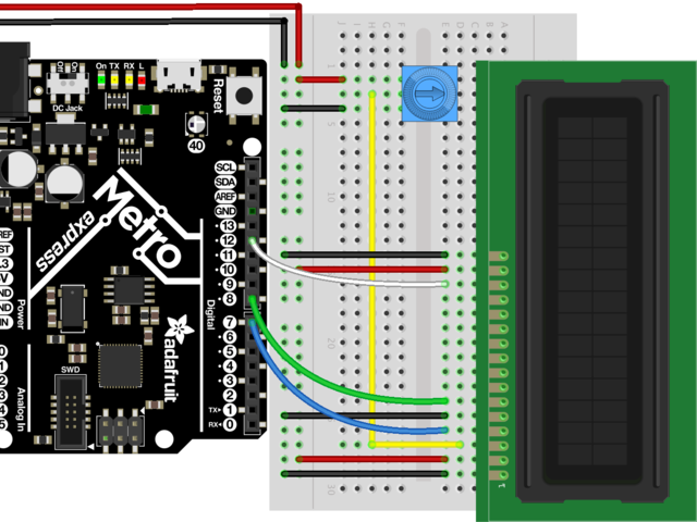
接下来是第一个数据引脚DB7。我们使用白线将 LCD Pin 14 连接到 Metro Digital Pin 12
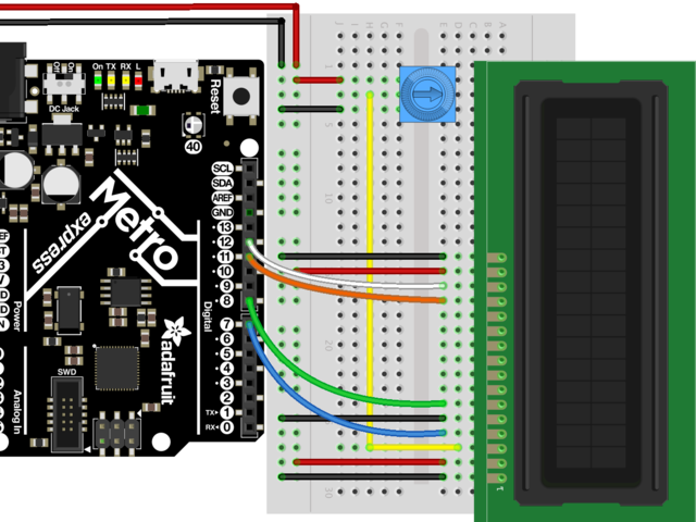
DB6 接下来是。我们使用橙色线将 LCD Pin 13 连接到 Metro Digital Pin 11

从 LCD引脚12连接 DB5 (我们使用紫线)到 Metro DigitalPin 10。
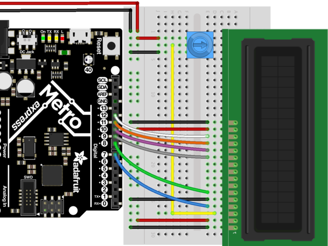
最后,我们用一条灰线将 DB4 连接到 LCD Pin 11 到 Metro DigitalPin 9
检查您是否拥有数据引脚之间的4线间隙是这样的:
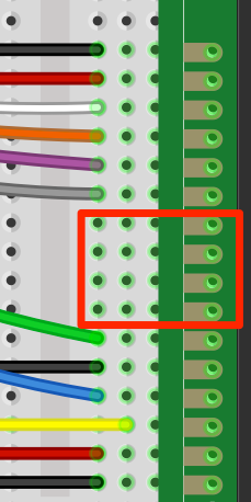
这是您应该在办公桌上看到的内容,请转到代码部分af ter仔细检查一下接线:
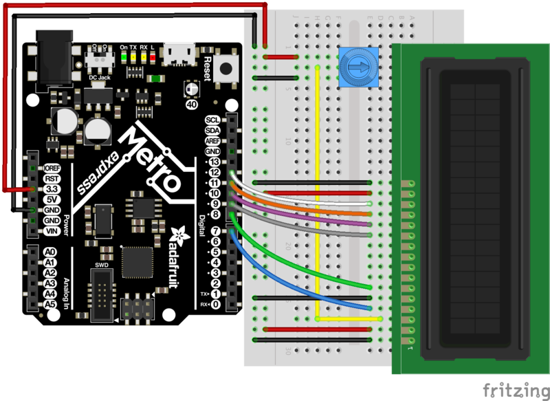
代码
将以下代码复制并粘贴到新的Arduino草图中。然后,将其编译并上传到Metro或Metro Express。
请勿这个CIRC尚未分开。。. CIRC15使用LCD,并且您不想再次连接它。
下载:Project Zip 或 CIRC14_CHAR_LCD.ino | 在Github上查看
复制代码
/*
LiquidCrystal Library - Hello World
Demonstrates the use a 16x2 LCD display. The LiquidCrystal
library works with all LCD displays that are compatible with the
Hitachi HD44780 driver. There are many of them out there, and you
can usually tell them by the 16-pin interface.
This sketch prints “Hello World!” to the LCD
and shows the time.
The circuit:
* LCD RS pin to digital pin 12
* LCD Enable pin to digital pin 11
* LCD D4 pin to digital pin 5
* LCD D5 pin to digital pin 4
* LCD D6 pin to digital pin 3
* LCD D7 pin to digital pin 2
* LCD R/W pin to ground
* LCD VSS pin to ground
* LCD VCC pin to 5V
* 10K resistor:
* ends to +5V and ground
* wiper to LCD VO pin (pin 3)
Library originally added 18 Apr 2008
by David A. Mellis
library modified 5 Jul 2009
by Limor Fried (http://www.ladyada.net)
example added 9 Jul 2009
by Tom Igoe
modified 22 Nov 2010
by Tom Igoe
This example code is in the public domain.
http://www.arduino.cc/en/Tutorial/LiquidCrystal
*/
// include the library code:
#include
// initialize the library with the numbers of the interface pins
// modified for Metro Explorers Guide
LiquidCrystal lcd(7, 8, 9, 10, 11, 12);
void setup() {
// set up the LCD‘s number of columns and rows:
lcd.begin(16, 2);
// Print a message to the LCD.
lcd.print(“hello, world!”);
}
void loop() {
}
/*
LiquidCrystal Library - Hello World
Demonstrates the use a 16x2 LCD display. The LiquidCrystal
library works with all LCD displays that are compatible with the
Hitachi HD44780 driver. There are many of them out there, and you
can usually tell them by the 16-pin interface.
This sketch prints “Hello World!” to the LCD
and shows the time.
The circuit:
* LCD RS pin to digital pin 12
* LCD Enable pin to digital pin 11
* LCD D4 pin to digital pin 5
* LCD D5 pin to digital pin 4
* LCD D6 pin to digital pin 3
* LCD D7 pin to digital pin 2
* LCD R/W pin to ground
* LCD VSS pin to ground
* LCD VCC pin to 5V
* 10K resistor:
* ends to +5V and ground
* wiper to LCD VO pin (pin 3)
Library originally added 18 Apr 2008
by David A. Mellis
library modified 5 Jul 2009
by Limor Fried (http://www.ladyada.net)
example added 9 Jul 2009
by Tom Igoe
modified 22 Nov 2010
by Tom Igoe
This example code is in the public domain.
http://www.arduino.cc/en/Tutorial/LiquidCrystal
*/
// include the library code:
#include
// initialize the library with the numbers of the interface pins
// modified for Metro Explorers Guide
LiquidCrystal lcd(7, 8, 9, 10, 11, 12);
void setup() {
// set up the LCD’s number of columns and rows:
lcd.begin(16, 2);
// Print a message to the LCD.
lcd.print(“hello, world!”);
}
void loop() {
}
不起作用?
我的字符LCD没有点亮。
仔细检查您与字符LCD的电源和背光引脚的接线连接是否正确。检查您的焊点,也许是有问题的。
还要检查您使用的是 5v Pin 而不是 3.3V Pin。
我只在液晶显示屏上看到黑色块
尝试扭曲电位计。您的数据总线也可能未正确连接。
我什么都没看到
重新接线LCD是消除任何问题的好方法,虽然要花费很多时间,但要确保一切正常正确。如果其他所有方法都失败,请在Adafruit支持论坛中发布,我们将尽快与您联系。
变得更好
第二行
如果要写入第二行,可以使用lcd.setCursor(COLUMN, LINE),以使列为0,行为1:
lcd.setCursor(0,1);
下载:文件
复制代码
void loop() {
// set the cursor to column 0, line 1
// (note: line 1 is the second row, since counting begins with 0):
lcd.setCursor(0, 1);
// print the number of seconds since reset:
lcd.print(millis() / 1000);
} void loop() {
// set the cursor to column 0, line 1
// (note: line 1 is the second row, since counting begins with 0):
lcd.setCursor(0, 1);
// print the number of seconds since reset:
lcd.print(millis() / 1000);
}
请勿分解CIRC尚未使用,CIRC15使用LCD,并且您不想再次连接它。
将光传感器写入LCD
让我们尝试将光传感器的输出写入字符LCD。
这将需要额外的一部分:
照片传感器
如果您想从Adafruit商店订购另一个光敏电阻,请单击此处!
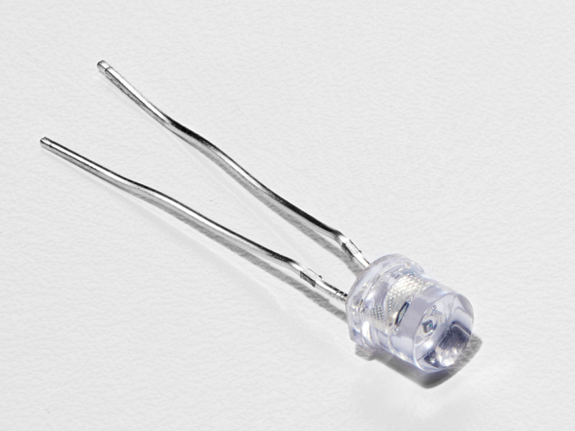
接线
Metro和Metro Express的“使它变得更好”的接线是相同的。确保导轨连接到5V。
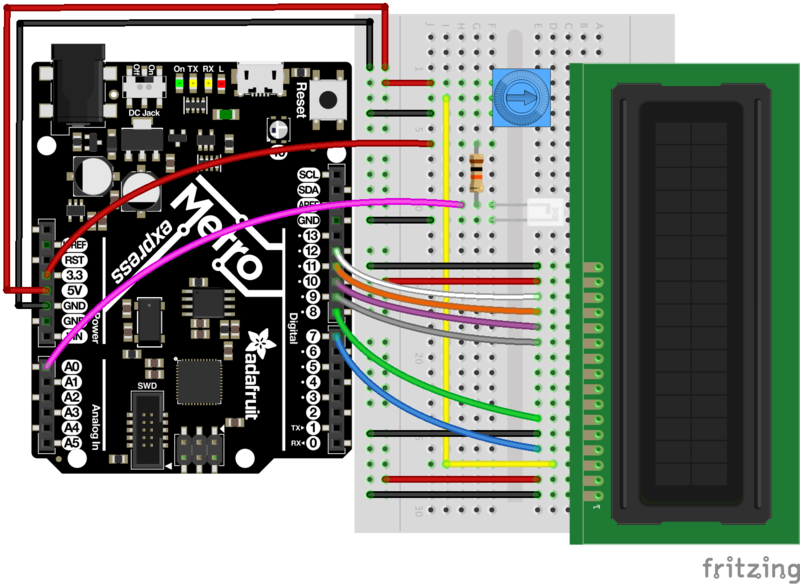
注意:当导轨连接到5V时,光传感器连接到3V。
代码
复制并粘贴下面的代码进入Arduino编辑器。然后,编译并将其上传到您的电路板上。
下载:文件
复制代码
/* CIRC14 - Make It Better
* Character LCD + TMP36
*
* by Brent Rubell for Adafruit Industries. Support Open Source, buy Adafruit!
*/
// include the library code:
#include
// modified wiring for Metro Explorers Guide
LiquidCrystal lcd(7, 8, 9, 10, 11, 12);
// photo light sensor
int lightPin = A0;
void setup() {
// set up the LCD‘s number of columns and rows:
lcd.begin(16, 2);
// print to the first line of the LCD
lcd.print(“Light Value:”);
}
void loop() {
// read the light level
int lightLevel = analogRead(lightPin);
// map and constrain the light sensor values
lightLevel = map(lightLevel, 0, 900, 0, 255);
lightLevel = constrain(lightLevel, 0, 255);
// set the cursor to column 0, line 1
lcd.setCursor(0, 1);
// write lightLevel to the LCD
lcd.print(lightLevel);
}
/* CIRC14 - Make It Better
* Character LCD + TMP36
*
* by Brent Rubell for Adafruit Industries. Support Open Source, buy Adafruit!
*/
// include the library code:
#include
// modified wiring for Metro Explorers Guide
LiquidCrystal lcd(7, 8, 9, 10, 11, 12);
// photo light sensor
int lightPin = A0;
void setup() {
// set up the LCD’s number of columns and rows:
lcd.begin(16, 2);
// print to the first line of the LCD
lcd.print(“Light Value:”);
}
void loop() {
// read the light level
int lightLevel = analogRead(lightPin);
// map and constrain the light sensor values
lightLevel = map(lightLevel, 0, 900, 0, 255);
lightLevel = constrain(lightLevel, 0, 255);
// set the cursor to column 0, line 1
lcd.setCursor(0, 1);
// write lightLevel to the LCD
lcd.print(lightLevel);
}
下一步是什么?
温度计(CIRC15)进入字符LCD的实质。您将学习如何显示自定义字符,完整的文本字符串以及多行数据输出!
CIRC15:温度计
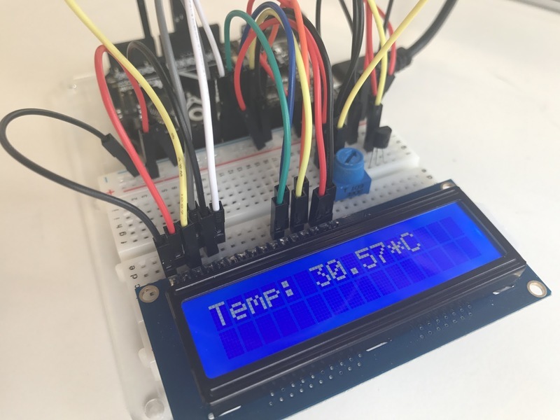
如果您想显示更多的输出而不是一堆LED可以处理的怎么办?当然,您可以设置一堆LED来显示数字。但是,如果还有另一种方法呢……
字符LCD超级坚固并且非常适合输出。当您放入 LiquidCrystal 库时,您可以在代码中输出任何到16(行)乘2(行)屏幕上的代码,这些代码可以让我们您将在电路中添加新功能。
我们将重新创建CIRC10。但是,我们将打印到外部字符LCD,而不是打印到串行监视器。
零件
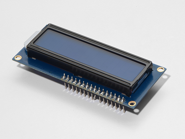
16x2字符LCD
如果您想从Adafruit商店购买蓝白色的16x2字符LCD,请单击此处!
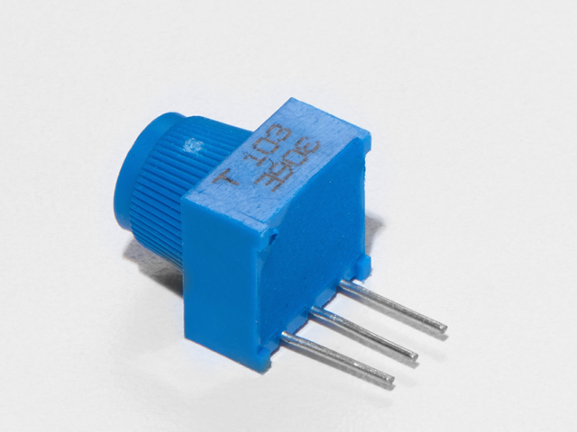
面包板微调电位器-10k
如果您想从Adafruit商店购买一个额外的微调锅,请单击此处!
此电路使用的是TMP36,而不是NPN晶体管。
我是使用 TMP36温度传感器或 NPN晶体管
《台式s =“ build-table”》
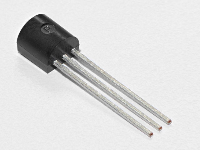
模拟温度传感器
如果您想要一个额外的温度传感器,可以从Adafruit商店购买一个,单击此处
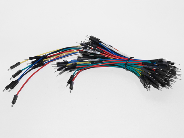
面包板接线束
如果您想从Adafruit商店订购更多电线,请点击此处!
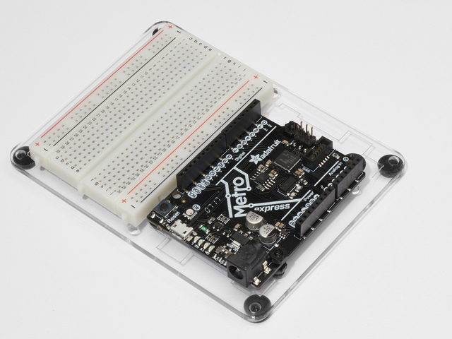
Adafruit Metro(或Metro Express)+面包板+安装板
如果尚未组装此产品,我们有一个方便的指南!
如果您想订购额外的塑料安装座或点击Adafruit Shop中的Adafruit Metro,AdafruitMetro Express或Mini-Breadboard,请点击此处!
接线
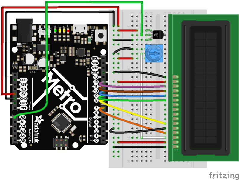
字符LCD的接线可能很棘手。有一个学习指南,贯穿每条电线。如果要使用它,请确保将LCD放在面包板的右侧,以确保您也可以将电位计和TMP36传感器安装在面包板上。
代码
CIRC15使用的代码适用于 Metro和Metro Express。两者都需要。 对其进行修改,以使其能够与您拥有的Metro一起使用。(如果不确定您所拥有的板,请单击此处!)。
如果您正在使用Metro Express,请将#define ANALOGREFVOLTAGE更改为#define ANALOGREFVOLTAGE 3.333
代码:
下载:Project Zip 或 CIRC15_THERMOMETER.ino | 在Github上查看
复制代码
/*
* CIRC15: Digital Thermometer
* Experimenter‘s Guide for Metro (and Metro Express!)
* by Brent Rubell for Adafruit Industries ~ Support Open Source, buy adafruit!
*/
// If you’re using a METRO EXPRESS, change this value to 3.333
#define ANALOGREFVOLTAGE 5.000
// include the lcd library code:
#include
// initialize the library with the numbers of the interface pins
LiquidCrystal lcd(7, 8, 9, 10, 11, 12);
// TMP36 Pin
int temperaturePin = 0;
void setup() {
Serial.begin(9600);
// set up the LCD‘s number of columns and rows:
lcd.begin(16, 2);
}
void loop() {
float temperature = 0;
temperature = getVoltage(temperaturePin);
/* Output: Degrees C */
temperature = (temperature - .5) * 100;
/* Output: Degrees F */
// temperature = (((temperature - .5) * 100)*1.8) + 32;
/* Output: Voltage */
// temperature = (temperature - .5) * 100; d
// Write temperature to the LCD
lcd.print(“Temp: ”);
lcd.setCursor(6,0);
lcd.print(temperature);
lcd.setCursor(11,0);
lcd.print(“*C”);
// Wait 1s
delay(1000);
// Refresh the LCD
lcd.clear();
}
float getVoltage(int pin) {
return(float(analogRead(pin))* float(ANALOGREFVOLTAGE/1023.000));
}
/*
* CIRC15: Digital Thermometer
* Experimenter’s Guide for Metro (and Metro Express!)
* by Brent Rubell for Adafruit Industries ~ Support Open Source, buy adafruit!
*/
// If you‘re using a METRO EXPRESS, change this value to 3.333
#define ANALOGREFVOLTAGE 5.000
// include the lcd library code:
#include
// initialize the library with the numbers of the interface pins
LiquidCrystal lcd(7, 8, 9, 10, 11, 12);
// TMP36 Pin
int temperaturePin = 0;
void setup() {
Serial.begin(9600);
// set up the LCD’s number of columns and rows:
lcd.begin(16, 2);
}
void loop() {
float temperature = 0;
temperature = getVoltage(temperaturePin);
/* Output: Degrees C */
temperature = (temperature - .5) * 100;
/* Output: Degrees F */
// temperature = (((temperature - .5) * 100)*1.8) + 32;
/* Output: Voltage */
// temperature = (temperature - .5) * 100; d
// Write temperature to the LCD
lcd.print(“Temp: ”);
lcd.setCursor(6,0);
lcd.print(temperature);
lcd.setCursor(11,0);
lcd.print(“*C”);
// Wait 1s
delay(1000);
// Refresh the LCD
lcd.clear();
}
float getVoltage(int pin) {
return(float(analogRead(pin))* float(ANALOGREFVOLTAGE/1023.000));
}
上传此代码后,请确保背光灯亮起并扭转电位计,直到您可以清楚地看到文本/数字。
有问题吗?
我在LCD上看不到任何东西
尝试扭曲电位计。如果那不起作用,请重新检查您的接线。
LCD上的文本是奇怪的字符或乱码
确保LCD的引脚与面包板齐平。如果不起作用,请从Arduino重新上传草图。
LCD上的数字不可能,太高/太低
所包含的代码中有一行使用串行监视器。弹出打开串行监视器,并根据您认为的当前温度检查其中的编号。如果数字似乎不正确,请仔细检查与模拟引脚A0的接线。
我仍然遇到麻烦,我认为图中太复杂了。
字符LCD上有一个 lot
变得更好
使用华氏温度
我们将把示例代码显示的度数转换为摄氏度,以华氏度为单位。在loop()中,更改以下行:
下载:文件
复制代码
// Degrees C
//temperature = (temperature - .5) * 100;
// Degrees F
temperature = (((temperature - .5) * 100)*1.8) + 32;
// Degrees C
//temperature = (temperature - .5) * 100;
// Degrees F
temperature = (((temperature - .5) * 100)*1.8) + 32;
然后,将草图编译并上传到Metro并观察编号变化。
在LCD上打印新文本
注意到即使编号更改了, * C 仍被打印到您的显示器上吗?这是因为* C被硬编码到显示器中。
要将* C更改为* F,请更改以下行:
lcd.print(“*C”); - 》 lcd.print(“*F”);
然后编译并上传到Metro。您的温度应显示华氏单位和温度符号。
打印到SecondRow
简介中提到此LCD为16x2。您可以打印两行行,但我们仅使用其中一行。让我们将 * F 符号打印到第二行的同一位置。为此,请在您的loop()中修改以下代码:
下载:文件
复制代码
lcd.setCursor(11,1); // instead of (11,0), we are printing to (11,1), the 2nd row
lcd.print(“*F”); lcd.setCursor(11,1); // instead of (11,0), we are printing to (11,1), the 2nd row
lcd.print(“*F”);
使用自定义字符
LiquidCrystal库包含一个名为createchar() 的命令,该命令可以为以下命令创建自定义字符(字形!)打印到液晶显示屏。我们的代码使用星号代替度数符号。让我们完成恒温器并使用 real 度符号。
为此,请在您的 setup()循环上方添加以下代码:
下载:文件
复制代码
// Custom Degree Symbol
byte degree[8] = {
0x7,
0x5,
0x7,
0x0,
0x0,
0x0,
0x0,
}; // Custom Degree Symbol
byte degree[8] = {
0x7,
0x5,
0x7,
0x0,
0x0,
0x0,
0x0,
};
在setup()循环中,添加以下行:
lcd.createChar(0,degree);
最后,在 loop()中修改以下行:
下载:文件
复制代码
lcd.setCursor(11,1);
lcd.write(byte(0)); // custom degrees character
lcd.setCursor(12,1);
lcd.print(“F”); lcd.setCursor(11,1);
lcd.write(byte(0)); // custom degrees character
lcd.setCursor(12,1);
lcd.print(“F”);
编译并上传后,您应该在F旁边看到度数符号。
制作自己的自定义字符
如果您想添加更多或其他自定义字符,我们会提供一个很棒的在线生成器。您可以根据需要添加自己的图标。让我们学习如何执行此操作:
首先,访问HD44780图形生成器站点。然后,将字符大小更改为 5 x 8
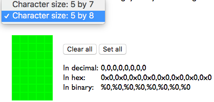
单击框设置像素。设置像素后,它将从绿色变为黑色。您可以通过单击黑色像素(打开)以使其变为绿色(关闭)来取消设置像素。
自定义字符后,复制“ In Hex”中的值并将其作为字节数组粘贴到Arduino草图中:
下载:文件
复制代码
// smiley face
byte smile[8] = {
0x0,
0x0,
0x8,
0x0,
0x0,
0x0,
0x0,
}; // smiley face
byte smile[8] = {
0x0,
0x0,
0x8,
0x0,
0x0,
0x0,
0x0,
};
在setup()循环中,添加以下行:
lcd.createChar(0,smile);
然后,在loop()中添加以下内容以将您的自定义字符写入LCD:
lcd.write(byte(0)); // custom degrees character
CIRC16:红外传感器
红外接收器传感器经过光电调节,可以接收红外频率。人眼看不到红外频率,但可以通过网络摄像头或手机拾取。
尝试按Mini Remote Control或电视/DVD播放器遥控器上的按钮,然后将其照在您的网络摄像头上。您看到的由遥控器发出的光是红外光。。这些红外信号是带有脉冲(标记)和间隔(空格)的32位PWM信号。
《实验者指南》使用IRLib,这是一个易于理解的Arduino库,可消除红外光接收器的神秘感。在代码部分,我们将遍历安装该库并将其用于此电路。
零件
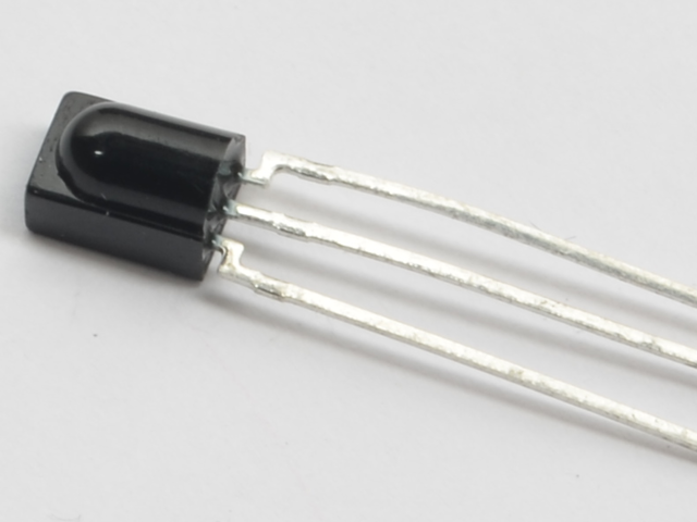
IR(红外)接收器传感器
如果您想在Adafruit商店订购额外的IR接收器传感器,请单击此处!

小型遥控器
我们建议将此遥控器与CIRC15一起使用,但您可以使用任何遥控器
如果您想从Adafruit商店订购额外的迷你遥控器,请单击此处!
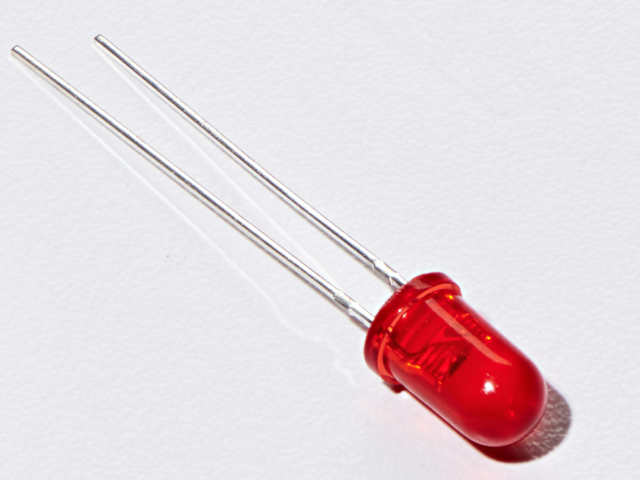
5mm红色LED
如果您想从A处订购更多红色LED(它们使指示灯亮!)。 dafruit商店,请单击此处!
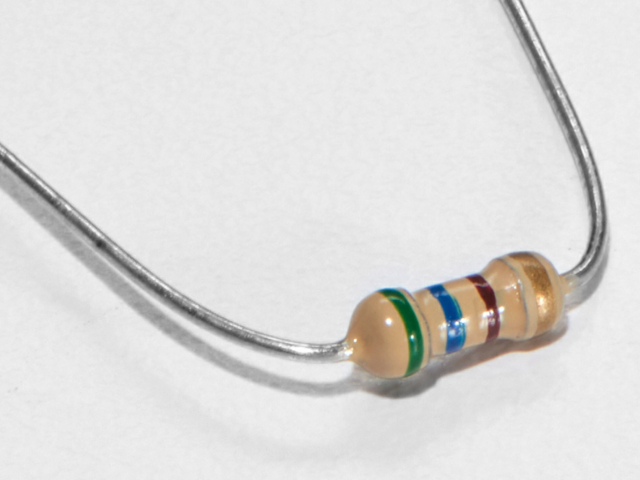
560欧姆电阻
颜色:绿色》蓝色》棕色
如果想从Adafruit商店订购更多电阻,请点击这里! (它们的电阻为470欧姆,但可以用)
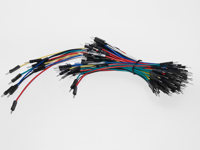
面包板接线束
如果您想从Adafruit商店订购更多电线,请单击此处!
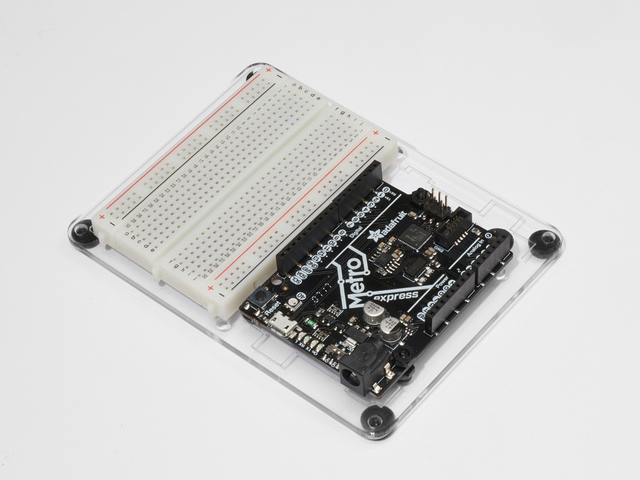
Adafruit Metro(或Metro Express)+面包板+安装板
如果您尚未组装,我们将为您提供方便的指南!
如果d想从Adafruit商店订购额外的塑料安装板,Adafruit Metro,AdafruitMetro Express或Mini-Breadboard,请点击此处!
接线
请勿将数字引脚6以外的其他任何数字引脚用于
此电路的接线与Metro和Metro Express的相同相同。
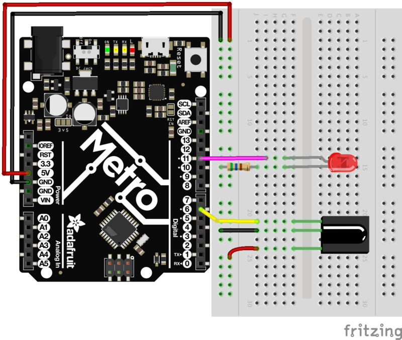
安装IR库
库
《实验者指南》使用 IRLib2 ,这是一个易于理解的Arduino库,可消除红外光接收器的神秘感。它使编写红外接收器和红外LED的代码变得更加容易。
安装IR库
下载最新的红外库
要安装IR库,请执行以下操作:
单击上面的按钮下载IR库,或直接从Github的IRLib 2.x库下载它。
下载完成后解压缩ZIP文件。
检查未压缩的文件夹是否包含五个单独的文件夹。 IRLib 2.x包含多个可协同工作的库。
将所有五个复制到您的Arduino Library文件夹根目录中。该路径通常位于(主页)/Documents/Arduino/Libraries 中。如果没有看到/Libraries/文件夹,则可能需要自己创建一个。
重新启动Arduino IDE。
代码
确保您已遵循安装IR库页面。复制下面的代码并将其粘贴到空白的Arduino Sketch中。然后,编译代码并将其上传到您的Metro。
按下按钮1,LED将会亮起。任何其他按钮都将关闭LED。
Download:Project Zip 或 CIRC16_IR.ino | 在Github上查看
复制代码
/*
* Metro Explorers Guide
* CIRC16: IR Sensor
*
* Desc: Turns on and off a 5mm Red LED with Mini Remote (NEC)
* by Brent Rubell for Adafruit Industries. Support Open Source, buy Adafruit!
*
* Note: this sketch requires IRLIB2.x
*/
// include all IRLib 2.x libraries
#include
// These values are for the Adafruit Mini Remote (using the NEC Protocol)
#define MY_PROTOCOL NEC
// Handles NEC repeat codes
uint32_t Previous;
// button(s)
#define BUTTON_0 0xfd30cf
#define BUTTON_1 0xfd08f7
#define BUTTON_2 0xfd8877
#define BUTTON_3 0xfd48b7
#define BUTTON_4 0xfd28d7
#define BUTTON_5 0xfda857
#define BUTTON_6 0xfd6897
#define BUTTON_7 0xfd18e7
#define BUTTON_8 0xfd9867
#define BUTTON_9 0xfd58a7
// pin for the reciever
IRrecv myReceiver(6);
// decoder class
IRdecode myDecoder;
// LED PIN
int ledPin = 13;
void setup() {
// set the ledPin as an output
pinMode(ledPin, OUTPUT);
// enable the receiver
myReceiver.enableIRIn();
}
void loop() {
// if the receiver gets a signal
if(myReceiver.getResults()) {
// decode the signal
myDecoder.decode();
// set the decoder‘s protocol to the set protocol
if(myDecoder.protocolNum == MY_PROTOCOL) {
// if there
if(myDecoder.value == 0xFFFFFFFF) {
// keep the led set to the last button value
myDecoder.value = Previous;
}
// based on myDecoder.value, switch between button codes
switch(myDecoder.value) {
// Turn on the LED
case BUTTON_1:
digitalWrite(ledPin, HIGH);
break;
// otherwise, turn off the LED
default:
digitalWrite(ledPin, LOW);
break;
}
// keep the LED set to the last button value
Previous = myDecoder.value;
}
// enable the IR receiver
myReceiver.enableIRIn();
}
}
// sets the color of the RGB LED
void setColor(int* led, const boolean* color) {
for(int i = 0; i 《 3; i++) {
digitalWrite(led[i], color[i]);
}
}
/*
* Metro Explorers Guide
* CIRC16: IR Sensor
*
* Desc: Turns on and off a 5mm Red LED with Mini Remote (NEC)
* by Brent Rubell for Adafruit Industries. Support Open Source, buy Adafruit!
*
* Note: this sketch requires IRLIB2.x
*/
// include all IRLib 2.x libraries
#include
// These values are for the Adafruit Mini Remote (using the NEC Protocol)
#define MY_PROTOCOL NEC
// Handles NEC repeat codes
uint32_t Previous;
// button(s)
#define BUTTON_0 0xfd30cf
#define BUTTON_1 0xfd08f7
#define BUTTON_2 0xfd8877
#define BUTTON_3 0xfd48b7
#define BUTTON_4 0xfd28d7
#define BUTTON_5 0xfda857
#define BUTTON_6 0xfd6897
#define BUTTON_7 0xfd18e7
#define BUTTON_8 0xfd9867
#define BUTTON_9 0xfd58a7
// pin for the reciever
IRrecv myReceiver(6);
// decoder class
IRdecode myDecoder;
// LED PIN
int ledPin = 13;
void setup() {
// set the ledPin as an output
pinMode(ledPin, OUTPUT);
// enable the receiver
myReceiver.enableIRIn();
}
void loop() {
// if the receiver gets a signal
if(myReceiver.getResults()) {
// decode the signal
myDecoder.decode();
// set the decoder’s protocol to the set protocol
if(myDecoder.protocolNum == MY_PROTOCOL) {
// if there
if(myDecoder.value == 0xFFFFFFFF) {
// keep the led set to the last button value
myDecoder.value = Previous;
}
// based on myDecoder.value, switch between button codes
switch(myDecoder.value) {
// Turn on the LED
case BUTTON_1:
digitalWrite(ledPin, HIGH);
break;
// otherwise, turn off the LED
default:
digitalWrite(ledPin, LOW);
break;
}
// keep the LED set to the last button value
Previous = myDecoder.value;
}
// enable the IR receiver
myReceiver.enableIRIn();
}
}
// sets the color of the RGB LED
void setColor(int* led, const boolean* color) {
for(int i = 0; i 《 3; i++) {
digitalWrite(led[i], color[i]);
}
}
不起作用?
我看不到颜色变化
是你的吗? RGB LED是否正确接线?您使用的遥控器与MetroX或MetroX Express Kit中包含的遥控器不同吗?如果是这样,请查看CIRC17中使用不同红外源的示例。
i》
致命错误:IRLibAll.h:没有这样的文件或目录#include
IRLib 2.x库安装不正确。返回步骤并确保已安装。
我仍然看不到任何东西
断路不好玩,请在Adafruit支持论坛中发布,我们会尽快与您联系。
CIRC17:IR重播
我们将构建一个IR重播电路。该电路使用两者红外LED和红外传感器(您在CIRC15中使用了它)来构建一个电路,该电路可以记录和播放来自任何遥控器的红外信号。
Adafruit TV-B-Gone套件是此软件的一个很棒的应用程序,并且是一个非常有趣的应用程序,它可以关闭酒吧,商店或医生办公室中那些讨厌的电视。
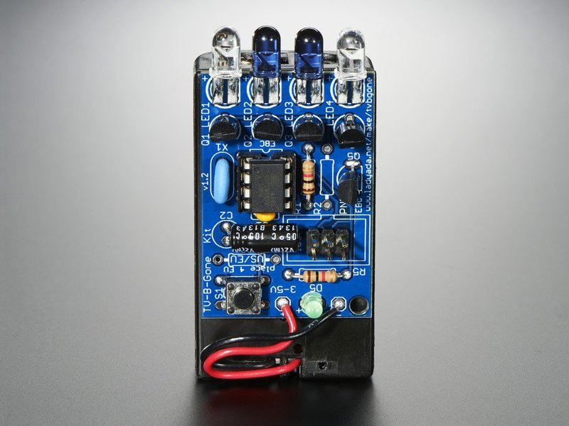
重放红外信号的概念在其他领域也非常有用。当收到特定的红外信号时,Somegarage开门器会打开车库。做一些探索,找出您拥有的设备受到红外信号的控制,并对其进行控制。
另一个应用程序是构建辅助设备,该设备可以帮助没有能够执行日常活动。您可以通过组合此电路和FSR来创建出色的辅助设备,从而对IR操作的任何物体进行踏板/按动操作的遥控器。
您甚至可以组合此电路和继电器用于CIRC11中,从附近的遥控器接收信号并控制继电器以切换直流供电设备(例如风扇或电灯)的电源。
零件
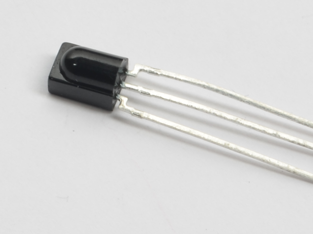
IR(红外)接收器传感器
如果您想在Adafruit商店订购额外的IR接收器传感器,请单击此处!
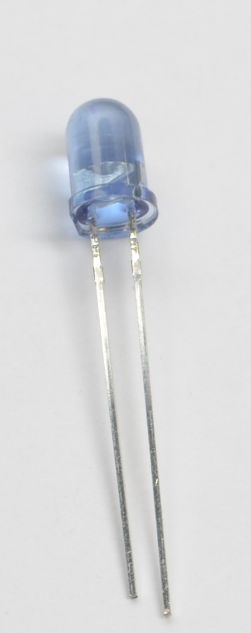
超高亮度5mm红外LED
如果您要要从Adafruit商店订购额外的5mm红外LED,请单击此处
此CIRC使用NPN晶体管,而不是TMP36。
《我使用的是 NPN晶体管或 TMP36 温度传感器
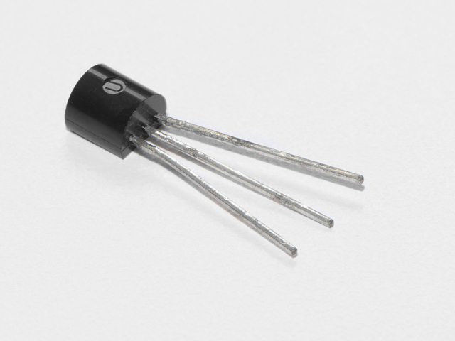
晶体管(PN2222或MPS2222)
如果您想从Adafruit商店订购额外的NPN晶体管,请点击此处!
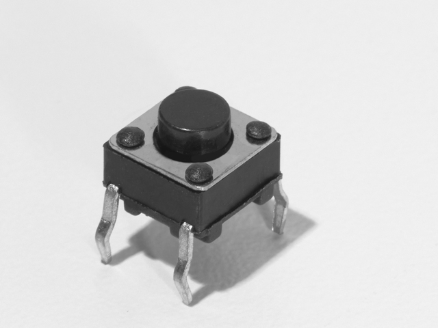
按钮 数量:x2
如果您想从Adafruit商店订购更多按钮,请单击此处!
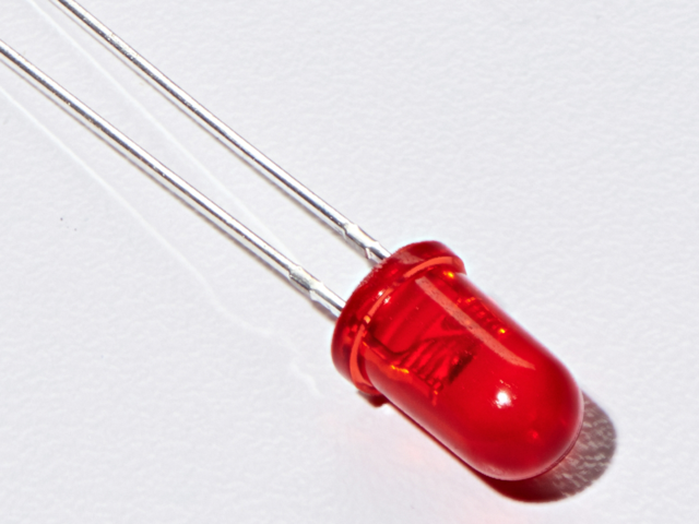
5mm红色LED
如果您要订购更多红色Adafruit商店的LED(它们使指示灯亮!),请点击此处!
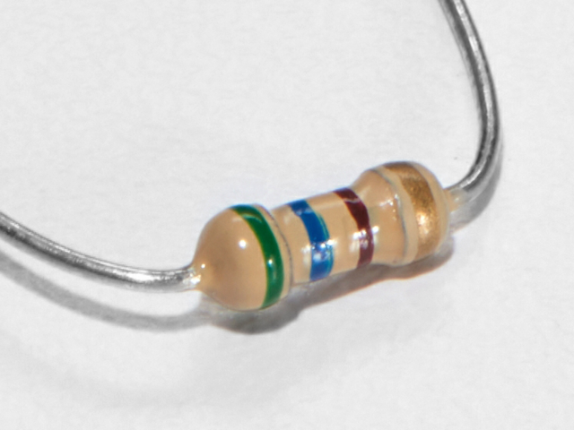
560欧姆电阻
颜色:绿色》蓝色》棕色
数量:x2
如果您想从Adafruit商店订购更多电阻,请单击此处! (它们的电阻为470欧姆,但可以用)
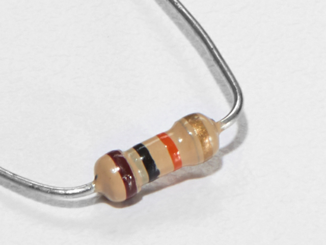
10K欧姆电阻
颜色:棕色》黑色》橙色
数量: x2
如果您想从Adafruit商店订购更多的10k欧姆上拉电阻,请单击此处!
小型遥控器(可选) )
您可以在该电路中使用任何遥控器。
如果您想从Adafruit商店订购额外的迷你遥控器,请单击此处!
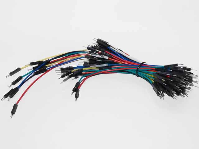
面包板接线束
如果您想从Adafruit商店订购更多电线,请点击此处!
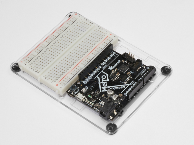
Adafruit Metro +面包板+安装板
如果您尚未组装,我们将为您提供方便的指南!
如果您想从以下位置订购额外的塑料安装板,Adafruit Metro或Mini-Breadboard: Adafruit Shop单击此处!
接线
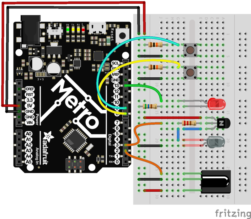
我们将许多组件隔开,以免它们在面包板上重叠。接线 NPN 晶体管时要小心-它必须具有特定的方向。
代码
您需要安装IRLIB2.x库才能使用CIRC17。如果需要安装,请单击此处!
将下面的代码复制并粘贴到Arduino编辑器中,然后进行编译并将其上传到您的开发板上。 p》
下载:文件
复制代码
/* CIRC17 - IR Replay
* Requires: IRLib 2.x Library
*
* record.ino by Chris Young
* modified by Brent Rubell for Adafruit Industries for the for the Metro (and Metro Express) Experimenters Guide. Support Open Source, buy Adafruit!
*/
/* IRLib */
#include //We need both the coding and
#include // sending base classes
#include //Lowest numbered protocol 1st
#include // Include only protocols you want
#include
#include
#include
#include
#include //We need this for IRsendRaw
#include // After all protocols, include this
// All of the above automatically creates a universal decoder
// class called “IRdecode” and a universal sender class “IRsend”
// containing only the protocols you want.
// Now declare instances of the decoder and the sender.
IRdecode myDecoder;
IRsend mySender;
// Include a receiver either this or IRLibRecvPCI or IRLibRecvLoop
#include
IRrecv myReceiver(2); //pin number for the receiver
// Storage for the recorded code
uint8_t codeProtocol; // The type of code
uint32_t codeValue; // The data bits if type is not raw
uint8_t codeBits; // The length of the code in bits
//These flags keep track of whether we received the first code
//and if we have have received a new different code from a previous one.
bool gotOne, gotNew;
/* Buttons */
// button -》 pin number
const int playBtn = 8;
const int recBtn = 9;
// hold the button states
int playBtnState = 0;
int recBtnState = 0;
// status LED
const int ledPin = 13;
void setup() {
gotOne=false; gotNew=false;
codeProtocol=UNKNOWN;
codeValue=0;
/* BTNS AND LED */
pinMode(ledPin, OUTPUT);
digitalWrite(ledPin, LOW);
pinMode(playBtn, INPUT);
pinMode(recBtn, INPUT);
Serial.begin(9600);
Serial.println(F(“Send a code from your remote and we will record it.”));
Serial.println(F(“Type any character and press enter. We will send the recorded code.”));
Serial.println(F(“Type ‘r’ special repeat sequence.”));
myReceiver.enableIRIn(); // Start the receiver
}
// Stores the code for later playback
void storeCode(void) {
gotNew=true; gotOne=true;
codeProtocol = myDecoder.protocolNum;
Serial.print(F(“Received ”));
Serial.print(Pnames(codeProtocol));
if (codeProtocol==UNKNOWN) {
Serial.println(F(“ saving raw data.”));
myDecoder.dumpResults();
codeValue = myDecoder.value;
}
else {
if (myDecoder.value == REPEAT_CODE) {
// Don‘t record a NEC repeat value as that’s useless.
Serial.println(F(“repeat; ignoring.”));
} else {
codeValue = myDecoder.value;
codeBits = myDecoder.bits;
}
Serial.print(F(“ Value:0x”));
Serial.println(codeValue, HEX);
}
}
void sendCode(void) {
if( !gotNew ) {//We‘ve already sent this so handle toggle bits
if (codeProtocol == RC5) {
codeValue ^= 0x0800;
}
else if (codeProtocol == RC6) {
switch(codeBits) {
case 20: codeValue ^= 0x10000; break;
case 24: codeValue ^= 0x100000; break;
case 28: codeValue ^= 0x1000000; break;
case 32: codeValue ^= 0x8000; break;
}
}
}
gotNew=false;
if(codeProtocol== UNKNOWN) {
//The raw time values start in decodeBuffer[1] because
//the [0] entry is the gap between frames. The address
//is passed to the raw send routine.
codeValue=(uint32_t)&(recvGlobal.decodeBuffer[1]);
//This isn’t really number of bits. It‘s the number of entries
//in the buffer.
codeBits=recvGlobal.decodeLength-1;
Serial.println(F(“Sent raw”));
}
mySender.send(codeProtocol,codeValue,codeBits);
if(codeProtocol==UNKNOWN) return;
Serial.print(F(“Sent ”));
Serial.print(Pnames(codeProtocol));
Serial.print(F(“ Value:0x”));
Serial.println(codeValue, HEX);
}
void loop() {
recBtnState = digitalRead(recBtn);
playBtnState = digitalRead(playBtn);
if(recBtnState == HIGH ) {
digitalWrite(ledPin, LOW);
myDecoder.decode();
// Re-enable receiver
myReceiver.enableIRIn();
digitalWrite(ledPin, HIGH);
}
if(playBtnState == HIGH) {
// check for stored signal
if(gotOne) {
// send the IR Code
sendCode();
// re-enable receiver
myReceiver.enableIRIn();
digitalWrite(ledPin, LOW);
}
}
}
/* CIRC17 - IR Replay
* Requires: IRLib 2.x Library
*
* record.ino by Chris Young
* modified by Brent Rubell for Adafruit Industries for the for the Metro (and Metro Express) Experimenters Guide. Support Open Source, buy Adafruit!
*/
/* IRLib */
#include //We need both the coding and
#include // sending base classes
#include //Lowest numbered protocol 1st
#include // Include only protocols you want
#include
#include
#include
#include
#include //We need this for IRsendRaw
#include // After all protocols, include this
// All of the above automatically creates a universal decoder
// class called “IRdecode” and a universal sender class “IRsend”
// containing only the protocols you want.
// Now declare instances of the decoder and the sender.
IRdecode myDecoder;
IRsend mySender;
// Include a receiver either this or IRLibRecvPCI or IRLibRecvLoop
#include
IRrecv myReceiver(2); //pin number for the receiver
// Storage for the recorded code
uint8_t codeProtocol; // The type of code
uint32_t codeValue; // The data bits if type is not raw
uint8_t codeBits; // The length of the code in bits
//These flags keep track of whether we received the first code
//and if we have have received a new different code from a previous one.
bool gotOne, gotNew;
/* Buttons */
// button -》 pin number
const int playBtn = 8;
const int recBtn = 9;
// hold the button states
int playBtnState = 0;
int recBtnState = 0;
// status LED
const int ledPin = 13;
void setup() {
gotOne=false; gotNew=false;
codeProtocol=UNKNOWN;
codeValue=0;
/* BTNS AND LED */
pinMode(ledPin, OUTPUT);
digitalWrite(ledPin, LOW);
pinMode(playBtn, INPUT);
pinMode(recBtn, INPUT);
Serial.begin(9600);
Serial.println(F(“Send a code from your remote and we will record it.”));
Serial.println(F(“Type any character and press enter. We will send the recorded code.”));
Serial.println(F(“Type ’r‘ special repeat sequence.”));
myReceiver.enableIRIn(); // Start the receiver
}
// Stores the code for later playback
void storeCode(void) {
gotNew=true; gotOne=true;
codeProtocol = myDecoder.protocolNum;
Serial.print(F(“Received ”));
Serial.print(Pnames(codeProtocol));
if (codeProtocol==UNKNOWN) {
Serial.println(F(“ saving raw data.”));
myDecoder.dumpResults();
codeValue = myDecoder.value;
}
else {
if (myDecoder.value == REPEAT_CODE) {
// Don’t record a NEC repeat value as that‘s useless.
Serial.println(F(“repeat; ignoring.”));
} else {
codeValue = myDecoder.value;
codeBits = myDecoder.bits;
}
Serial.print(F(“ Value:0x”));
Serial.println(codeValue, HEX);
}
}
void sendCode(void) {
if( !gotNew ) {//We’ve already sent this so handle toggle bits
if (codeProtocol == RC5) {
codeValue ^= 0x0800;
}
else if (codeProtocol == RC6) {
switch(codeBits) {
case 20: codeValue ^= 0x10000; break;
case 24: codeValue ^= 0x100000; break;
case 28: codeValue ^= 0x1000000; break;
case 32: codeValue ^= 0x8000; break;
}
}
}
gotNew=false;
if(codeProtocol== UNKNOWN) {
//The raw time values start in decodeBuffer[1] because
//the [0] entry is the gap between frames. The address
//is passed to the raw send routine.
codeValue=(uint32_t)&(recvGlobal.decodeBuffer[1]);
//This isn‘t really number of bits. It’s the number of entries
//in the buffer.
codeBits=recvGlobal.decodeLength-1;
Serial.println(F(“Sent raw”));
}
mySender.send(codeProtocol,codeValue,codeBits);
if(codeProtocol==UNKNOWN) return;
Serial.print(F(“Sent ”));
Serial.print(Pnames(codeProtocol));
Serial.print(F(“ Value:0x”));
Serial.println(codeValue, HEX);
}
void loop() {
recBtnState = digitalRead(recBtn);
playBtnState = digitalRead(playBtn);
if(recBtnState == HIGH ) {
digitalWrite(ledPin, LOW);
myDecoder.decode();
// Re-enable receiver
myReceiver.enableIRIn();
digitalWrite(ledPin, HIGH);
}
if(playBtnState == HIGH) {
// check for stored signal
if(gotOne) {
// send the IR Code
sendCode();
// re-enable receiver
myReceiver.enableIRIn();
digitalWrite(ledPin, LOW);
}
}
}
不起作用?
我没看到LED亮起
尝试打开Arduino串行监视器。这段代码中有Serial.print() 条语句可以帮助您调试。
我可以接收但不能发送IR信号
确保您的 NPN晶体管已正确连接,这是该电路所必需的。
我对此电路实在感到沮丧,调试后看不到任何输出
此电路特别棘手,因为红外传感器和接收器有点挑剔,张贴在Adafruit支持论坛上我们会尽快与您联系。
零件
此电路仅适用于Metro EXPRESS,而不适用于Metro Classic

Adafruit Metro Express +面包板+安装板
如果您尚未组装,我们将为您提供方便的指南!
需要Adafruit商店提供的额外的塑料安装板,Adafruit MetroExpress或Mini-Breadboard吗?
为Metro Express布线
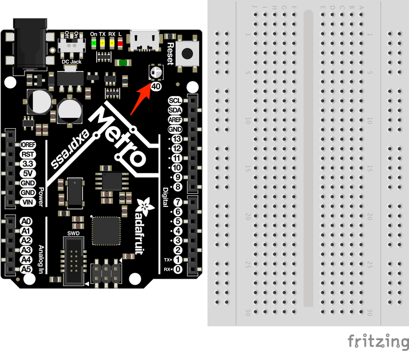
没有什么菜板! Metro Express具有板上所需的所有电路(包括NeoPixel!)。 NeoPixel已分配给Metro Express上的数字引脚40
代码
安装NeoPixel库
在复制和粘贴代码之前,您需要安装NeoPixel库。这比安装IR库要容易得多-您可以直接从IDE安装NeoPixel库!
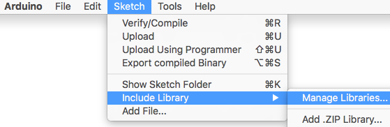
在Arduino中,转到 Sketch》 Include Library》 Manage Libraries。
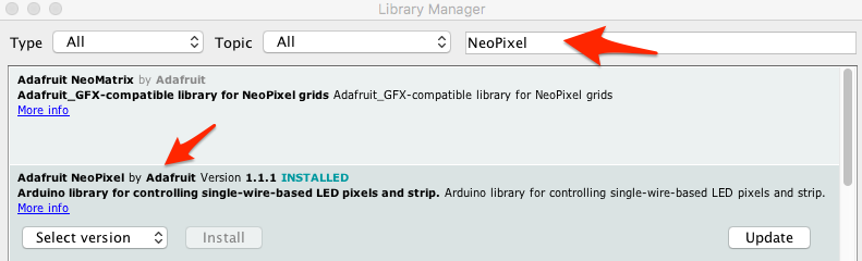
在库管理器中,搜索 NeoPixel 。
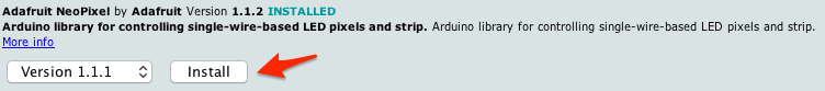
然后,找到最新版本(在撰写本文时为1.1.1),然后单击安装。
状态栏完成后,r 启动Arduino IDE 。 NeoPixel库已安装。
代码
复制/粘贴下面的代码。然后,将其编译并上传到Metro中。
您应该看到Metro的NeoPixels呈红色,白色,和蓝色。
下载:Project Zip 或 CIRC18_NEOPIXEL.ino | 在Github上查看
复制代码
/*
* (CIRC18) Metro Express NeoPixel
* this circuit was designed for use with the Metro Explorers Guide on Learn.Adafruit.com
*
* note: this code does NOT run on the Metro, only the Metro EXPRESS.
*
* by Brent Rubell for Adafruit Industries.
*/
// Include the Adafruit Neopixel Library
#include
// The default pin for the NeoPixel on the Metro Express is Pin #40
#define METROPIXELPIN 40
// metroPixel takes in both the number of pixels (1, the built-in) and the pin)
Adafruit_NeoPixel metroPixel = Adafruit_NeoPixel(1, METROPIXELPIN);
/* Colors */
// note: the max. of colors in these arrays is 220 instead of 255 (super-bright!!)
const int RED[ ] = {155, 0, 0};
const int WHITE[ ] = {155, 155, 155};
const int BLUE[ ] = {0, 0, 255};
const int BLACK [ ] = {0, 0, 0};
void setup() {
// init. the NeoPixel library
metroPixel.begin();
}
void loop() {
// display red on the Metro Express neopixel
pixelWrite(RED);
delay(1000);
// display white on the Metro Express neopixel
pixelWrite(WHITE);
delay(1000);
// display blue on the Metro Express neopixel
pixelWrite(BLUE);
delay(1000);
// Sparkle the Neopixel
// pixelSparkle();
}
// takes in a pre-defined color (integer array) and sets the pixel to that color
void pixelWrite(const int* color) {
metroPixel.setPixelColor(0, metroPixel.Color(color[0],color[1],color[2]));
// write the pixel color to the Metro‘s Neopixel
metroPixel.show();
}
// flashes the neopixel on and off rapidly
void pixelSparkle() {
for(int i = 0; i 《 5; i++) {
pixelWrite(BLACK);
delay(50);
pixelWrite(WHITE);
delay(50);
}
}
/*
* (CIRC18) Metro Express NeoPixel
* this circuit was designed for use with the Metro Explorers Guide on Learn.Adafruit.com
*
* note: this code does NOT run on the Metro, only the Metro EXPRESS.
*
* by Brent Rubell for Adafruit Industries.
*/
// Include the Adafruit Neopixel Library
#include
// The default pin for the NeoPixel on the Metro Express is Pin #40
#define METROPIXELPIN 40
// metroPixel takes in both the number of pixels (1, the built-in) and the pin)
Adafruit_NeoPixel metroPixel = Adafruit_NeoPixel(1, METROPIXELPIN);
/* Colors */
// note: the max. of colors in these arrays is 220 instead of 255 (super-bright!!)
const int RED[ ] = {155, 0, 0};
const int WHITE[ ] = {155, 155, 155};
const int BLUE[ ] = {0, 0, 255};
const int BLACK [ ] = {0, 0, 0};
void setup() {
// init. the NeoPixel library
metroPixel.begin();
}
void loop() {
// display red on the Metro Express neopixel
pixelWrite(RED);
delay(1000);
// display white on the Metro Express neopixel
pixelWrite(WHITE);
delay(1000);
// display blue on the Metro Express neopixel
pixelWrite(BLUE);
delay(1000);
// Sparkle the Neopixel
// pixelSparkle();
}
// takes in a pre-defined color (integer array) and sets the pixel to that color
void pixelWrite(const int* color) {
metroPixel.setPixelColor(0, metroPixel.Color(color[0],color[1],color[2]));
// write the pixel color to the Metro’s Neopixel
metroPixel.show();
}
// flashes the neopixel on and off rapidly
void pixelSparkle() {
for(int i = 0; i 《 5; i++) {
pixelWrite(BLACK);
delay(50);
pixelWrite(WHITE);
delay(50);
}
}
遇到麻烦了?
我的代码无法编译
请确保NeoPixel库已正确安装在右侧位置。
我看不到NeoPixe我在董事会上。
您必须拥有 Metro ,而不是 Metro Express 。该电路仅适用于Metro Express 。
我仍然看不到任何东西
在Adafruit支持论坛中发布,我们将尽快与您联系。
变得更好
调暗NeoPixel
哇,NeoPixel肯定很亮,是吗?有一种非常简单的方法可以将其变暗。 NeoPixel的取值范围是0到255,最亮的是255。
让它变暗100。在您的代码中,将:
const int RED[ ] = {255, 0, 0}; 更改为 const int RED[ ] = {155, 0, 0};
仍然太亮吗?让我们将其更改为1/3,方法是将
const int GREEN[ ] = {128, 255, 0};更改为const int GREEN[ ]= {128/3, 255/3, 0};
NeoPixel凝视温度计
我们将要进行修改温度计电路,以使用NeoPixel组装颜色编码的温度计。瞥一眼该电路,查看与特定温度对应的颜色。
接线

此电路的接线很简单-只需将温度传感器接线即可。
代码
复制/粘贴以下代码。然后,将其编译并上传到您的Metro Express!
下载:文件
复制代码
/*
* CIRC18 Make It Better
* NeoPixel Glance Thermometer - check the weather super quickly!
*
* by Brent Rubell for Adafruit Industries
*/
// Include the Adafruit Neopixel Library
#include
// The default pin for the NeoPixel on the Metro Express is Pin #40
#define METROPIXELPIN 40
// Temperature Sensor
const int temperaturePin = A0;
// metroPixel takes in both the number of pixels (1, the built-in) and the pin)
Adafruit_NeoPixel metroPixel = Adafruit_NeoPixel(1, METROPIXELPIN);
float temperature = 0;
/* Temperature Colors */
const int RED[ ] = {255, 0, 0};
const int ORANGE[ ] = {255, 153, 51};
const int YELLOW[ ] = {255, 255, 0};
const int LIGHTGREEN[ ] = {128, 255, 0};
const int DARKGREEN[ ] = {76, 153, 0};
const int DARKBLUE[ ] = {0, 0, 255};
const int DARKPURPLE[ ] = {51, 0, 102};
const int BLACK[ ] = {0, 0, 0};
void setup()
{
// Start the Serial at 9600 baud
Serial.begin(9600);
// init the neopixel library
metroPixel.begin();
}
void loop()
{
temperature = getVoltage3V(temperaturePin);
// Convert to degrees C
temperature = (temperature - .5) * 100;
// print the temperature in C to the serial
Serial.println(temperature);
// temp 《-》 color picker
if (temperature 》 40) {
// red
pixelWrite(RED);
}
else if (temperature 》 35) {
// orange
pixelWrite(ORANGE);
}
else if (temperature 》 30) {
// yellow
pixelWrite(YELLOW);
}
else if (temperature 》 25) {
// yellow
pixelWrite(LIGHTGREEN);
}
else if (temperature 》 20) {
// dark green
pixelWrite(DARKGREEN);
}
else if (temperature 》 5) {
// dark blue
pixelWrite(DARKBLUE);
}
else {
// dark purple
pixelWrite(DARKPURPLE);
}
delay(1000);
}
// takes in a pre-defined color (integer array) and sets the pixel to that color
void pixelWrite(const int* color) {
metroPixel.setPixelColor(0, metroPixel.Color(color[0],color[1],color[2]));
// write the pixel color to the Metro‘s Neopixel
metroPixel.show();
}
// Voltage to temperature if Vs= 3.3V
float getVoltage3V(int pin){
// 3.3V/1023
return (analogRead(pin) * 0.003225806452);
} /*
* CIRC18 Make It Better
* NeoPixel Glance Thermometer - check the weather super quickly!
*
* by Brent Rubell for Adafruit Industries
*/
// Include the Adafruit Neopixel Library
#include
// The default pin for the NeoPixel on the Metro Express is Pin #40
#define METROPIXELPIN 40
// Temperature Sensor
const int temperaturePin = A0;
// metroPixel takes in both the number of pixels (1, the built-in) and the pin)
Adafruit_NeoPixel metroPixel = Adafruit_NeoPixel(1, METROPIXELPIN);
float temperature = 0;
/* Temperature Colors */
const int RED[ ] = {255, 0, 0};
const int ORANGE[ ] = {255, 153, 51};
const int YELLOW[ ] = {255, 255, 0};
const int LIGHTGREEN[ ] = {128, 255, 0};
const int DARKGREEN[ ] = {76, 153, 0};
const int DARKBLUE[ ] = {0, 0, 255};
const int DARKPURPLE[ ] = {51, 0, 102};
const int BLACK[ ] = {0, 0, 0};
void setup()
{
// Start the Serial at 9600 baud
Serial.begin(9600);
// init the neopixel library
metroPixel.begin();
}
void loop()
{
temperature = getVoltage3V(temperaturePin);
// Convert to degrees C
temperature = (temperature - .5) * 100;
// print the temperature in C to the serial
Serial.println(temperature);
// temp 《-》 color picker
if (temperature 》 40) {
// red
pixelWrite(RED);
}
else if (temperature 》 35) {
// orange
pixelWrite(ORANGE);
}
else if (temperature 》 30) {
// yellow
pixelWrite(YELLOW);
}
else if (temperature 》 25) {
// yellow
pixelWrite(LIGHTGREEN);
}
else if (temperature 》 20) {
// dark green
pixelWrite(DARKGREEN);
}
else if (temperature 》 5) {
// dark blue
pixelWrite(DARKBLUE);
}
else {
// dark purple
pixelWrite(DARKPURPLE);
}
delay(1000);
}
// takes in a pre-defined color (integer array) and sets the pixel to that color
void pixelWrite(const int* color) {
metroPixel.setPixelColor(0, metroPixel.Color(color[0],color[1],color[2]));
// write the pixel color to the Metro’s Neopixel
metroPixel.show();
}
// Voltage to temperature if Vs= 3.3V
float getVoltage3V(int pin){
// 3.3V/1023
return (analogRead(pin) * 0.003225806452);
}
将NeoPixel添加到CIRC中
扫视温度计是对温度回路的修改。您完成了哪些保监会?您如何在电路中添加NeoPixel以增加功能,实用性或美观性?
零件
此CIRC仅适用于Metro Express,而不适用于Metro。组装此CIRC之前,请确认您正在使用Metro Express。
表格》 接线
这是Express线路上的电路,仅能使用
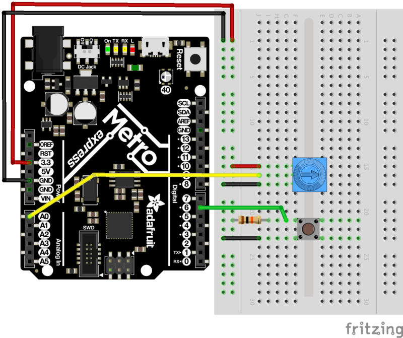
代码
USB-HID库内置于Arduino,不需要外部安装。确认您具有Metro Express,然后将以下代码复制并粘贴到Arduino编辑器中。然后,编译并上传。
下载:Project Zip 或 CIRC19_USB_BLOG_BUDDY .ino | 在Github上查看
复制代码
/*
* USB Blog Buddy
* a USB-HID Scroll Wheel for Metro Express
*
* by Brent Rubell for Adafruit Industries. Support Open Source, buy Adafruit!
*/
// include the mouse library
#include
// trimpot pin
const int trimPin = A0;
// button pin
const int buttonPin = 2;
// reduces scrolling speed (ms)
const int scrollDelay = 100;
// trimpot value
int trimValue = 0;
// button state
int buttonState = 0;
void setup() {
// start serial monitor at 9600 baud
Serial.begin(9600);
// start the mouse
Mouse.begin();
}
void loop() {
// read the button state
buttonState = digitalRead(buttonPin);
if (buttonState == HIGH) {
// stop the mouse if button not pressed
Mouse.end();
}
else {
// start the mouse (if stopped)
Mouse.begin();
// read the trimpot value
trimValue = analogRead(trimPin);
// map the trimValues to scroll wheel down (-neg values) and up (+pos values)
trimValue = map(trimValue, 0, 1023, -5, 5);
// move the mouse wheel (dont change cursor position)
Mouse.move(0, 0, trimValue);
// reduce the scrolling speed
delay(scrollDelay);
}
}
使用USB Blog Buddy
》
前往Adafruit博客以测试您的电路!
当您按下按钮时,Metro Express将控制您的鼠标并开始滚动鼠标滚轮。
向上滚动页面:移动电位计,使其箭头指向面包板顶部
向下滚动页面:移动电位计,使其箭头指向面包板的底部
不起作用?
我在屏幕上看不到任何东西
检查您的接线,用于USB接口的库已内置在Arduino中,并且在您上传此代码后应会自动启动。
仍然无法正常工作吗?
在Adafruit支持论坛中发布,我们将尽快与您联系。
零件
如果‘正在使用Metro Classic:
您需要一个 1M欧姆电阻。
如果您使用的是Metro M0 Express:
您不需要任何新零件,M0 Express电容式传感器已完全在芯片内部管理!
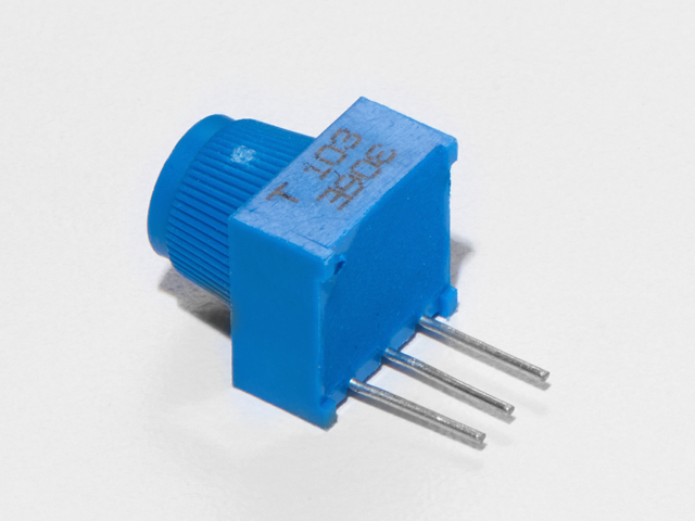
面包板微调电位器-10k
如果您要购买从Adafruit商店购买多余的修剪锅,请单击此处!
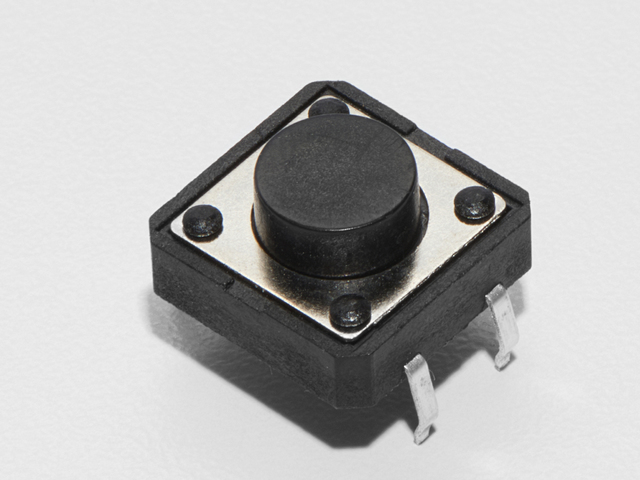
按钮
如果您想从Adafruit商店订购更多按钮,请单击此处!
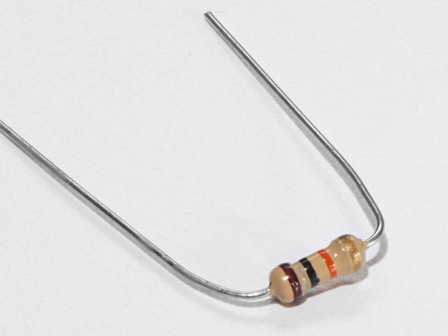
10K欧姆电阻
颜色:棕色》黑色》橙色
如果您愿意要从Adafruit商店订购更多的10k欧姆上拉电阻,请单击此处!
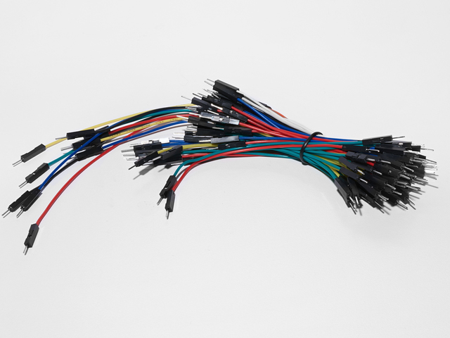
面包板接线束
如果您愿意要从Adafruit商店订购更多电线,请点击此处!
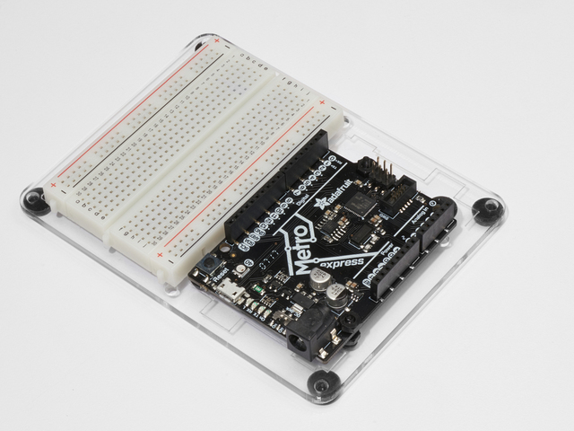
Adafruit Metro Express +面包板+安装板
如果您尚未组装,我们将为您提供方便的指南!
需要Adafruit商店提供的额外的塑料安装板,Adafruit MetroExpress或Mini-Breadboard吗?
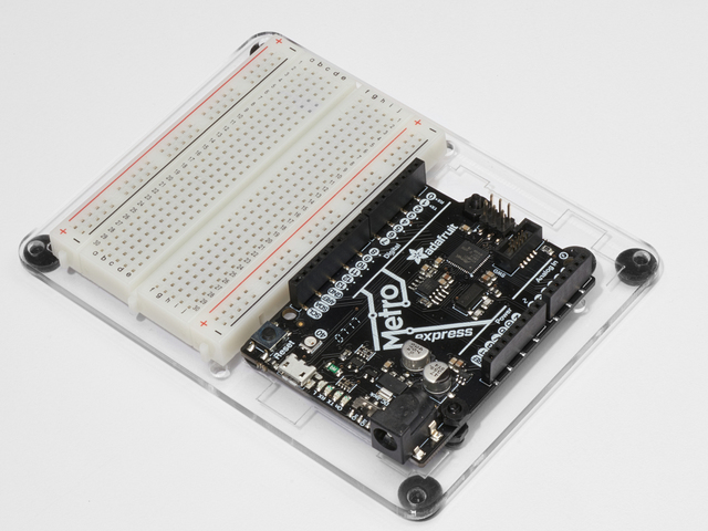
Adafruit Metro(或Metro Express)+面包板+安装板
如果您尚未组装此手册,我们将为您提供方便的指南!
如果您想订购额外的塑料安装板,Adafruit Metro,AdafruitMetro Express或Adafruit Shop的迷你面包板请单击此处!
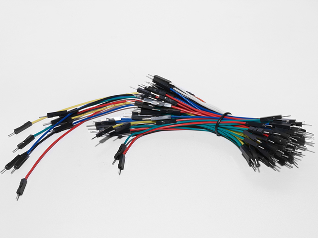
面包板接线束
如果想要从Adafruit商店订购更多电线,请点击此处!
接线
Metro Classic的接线
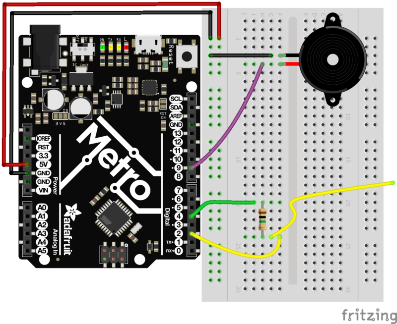
请注意电阻值!
您需要为此电路使用 1M欧姆电阻。从传感器引脚伸出的引脚(在我们的示例中为数字引脚2 ),最好是面包板捆绑包中的短引脚。
1M欧姆电阻色带:棕色》黑色》绿色》银色
Metro Express的接线

您不需要为此电路使用 1M欧姆电阻,只需较小的值(例如MetroX Classic和MetroX Express套件中包含的560欧姆)。 Metro Express的板载1M Ohm上拉电阻值。
为Metro Express布线
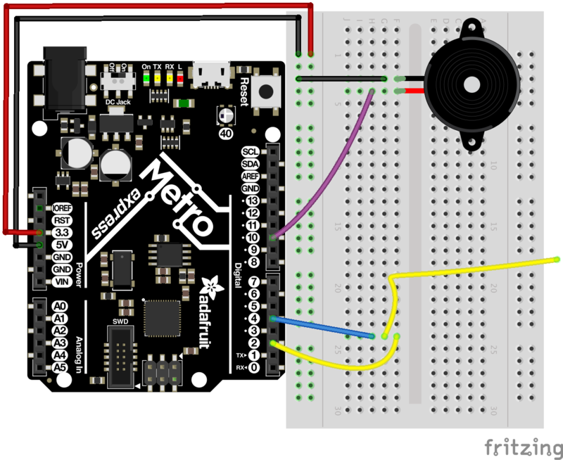
代码
您需要下载安装CapacitiveSensor库。
打开Arduino库管理器:
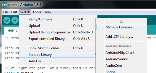
搜索电容式传感器并安装
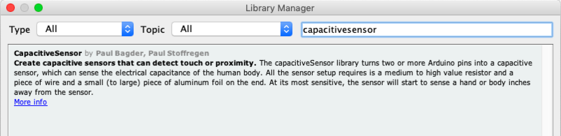
代码
下载并安装CapacitiveSensor库后,将以下代码复制并粘贴到Arduino IDE中。然后,编译并将其上传到您的Metro(或Metro Express)。
下载:文件
复制代码
/*
* CIRC20 - Capacitive Sensing with the Metro and Metro M0 Express
*
* by Brent Rubell for Adafruit Industries. Support Open Source Hardware, Buy Adafruit!
*/
#include
// piezo speaker pin
int piezoPin = 9;
// 10M resistor between pins 4 & 2, pin 2 is sensor pin, add a wire and or foil if desired
// put a 10M resistor between pins 4 & 2, pin 2 is the sensor pin, 4 is the receiver
CapacitiveSensor cs_4_2 = CapacitiveSensor(4,2);
void setup()
{
cs_4_2.set_CS_AutocaL_Millis(0xFFFFFFFF);
Serial.begin(9600);
// set the piezo as an output
pinMode(piezoPin, OUTPUT);
}
void loop()
{
long start = millis();
long pinTone = cs_4_2.capacitiveSensor(30);
Serial.print(“sensor value: ”); // check on performance in milliseconds
Serial.print(“ ”); // tab character for debug windown spacing
Serial.print(pinTone); // print sensor output 1
Serial.print(“ ”);
// map the tone value to frequencies between 500 and 2000
long mapTone = map(pinTone, 0, 40, 500, 2000);
// play the mapped tone
playTone(int(mapTone), 100);
delay(10);
}
void playTone(int tone, int duration) {
for (long i = 0; i 《 duration * 1000L; i += tone * 2) {
digitalWrite(piezoPin, HIGH);
delayMicroseconds(tone);
digitalWrite(piezoPin, LOW);
delayMicroseconds(tone);
}
}
此CIRC出现问题
没有听到任何声音?
打开Arduino串行监视器。当您按下图钉时,最大的sensor value是什么?最小的?在下面的留置权中,用找到的两个数字值替换MIN_SENSOR_VALUE和MAX_SENSOR_VALUE的值:
long mapTone = map(pinTone, MIN_SENSOR_VALUE, MAX_SENSOR_VALUE, 500, 2000);
传感器读数为0?
当您打开Arduino串行监视器时,是否看到 0 或- 2 的值?您使用的电阻可能太小。我们建议使用1M欧姆电阻,而不要使用10K欧姆电阻。那是一个 一百万 欧姆。如果您没有任何1M欧姆电阻,则可以使用任何其他类似的(非常大的)电阻。
这根本不起作用。
在Adafruit支持论坛中发布,我们将尽快与您联系。
变得更好
使用不同的输入类型
您可以为电容传感器使用许多不同类型的输入。其中包括来自苹果,盐水和器皿的所有物品(取决于材料)。您还可以使用Adafruit商店中的一些不同的导电材料,例如导电橡胶,机织导电织物(尝试将其用于可穿戴项目),甚至使用导电油漆笔将任何材料变成导电材料。
添加传感器输入
需要更多输入吗?您可以继续将数字引脚4 用于接收器引脚,并且可以使用任何其他数字引脚来创建电容传感器。
为此,只需在代码中添加一行:
CapacitiveSensor cs_4_# = CapacitiveSensor(4,#);
您需要用要用作传感器的数字引脚号替换#。
我们正在使用数字引脚4 作为接收器,数字引脚8 作为新传感器,因此,这里是面包板的外观:
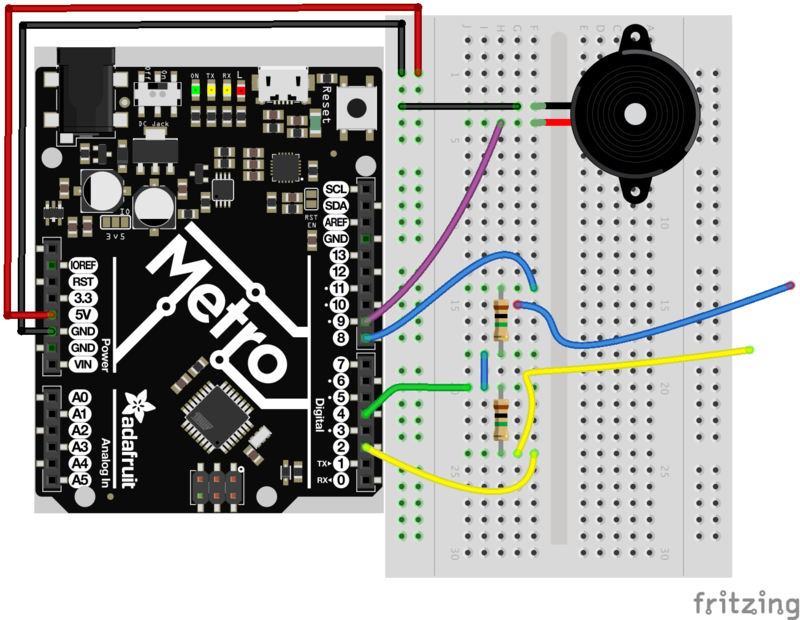
PROJ01:Theremin
您将成为 Thereminist !那里有一个陌生的乐器是aTheremin,这是一种电子乐器,您可以在其中挥动双手并制作音乐!您将使用以前的中国保监会的知识来指导自己。
零件
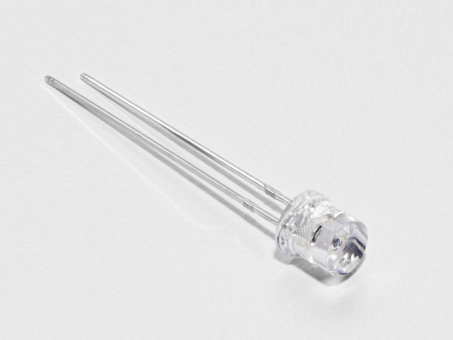
照片传感器
如果您想从Adafruit商店订购其他光敏电阻,请单击此处!
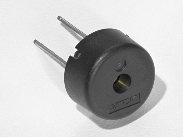
压电 蜂鸣器
如果您想从Adafruit商店订购另一个Pizeo蜂鸣器,请单击此处!
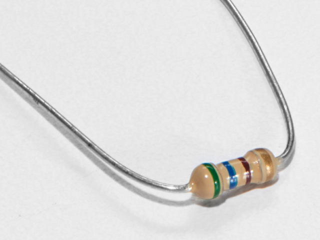
560欧姆电阻
颜色: 绿色》蓝色》棕色
如果您想从Adafruit sho订购更多电阻器p点击这里! (它们的电阻为470欧姆,但可以用)
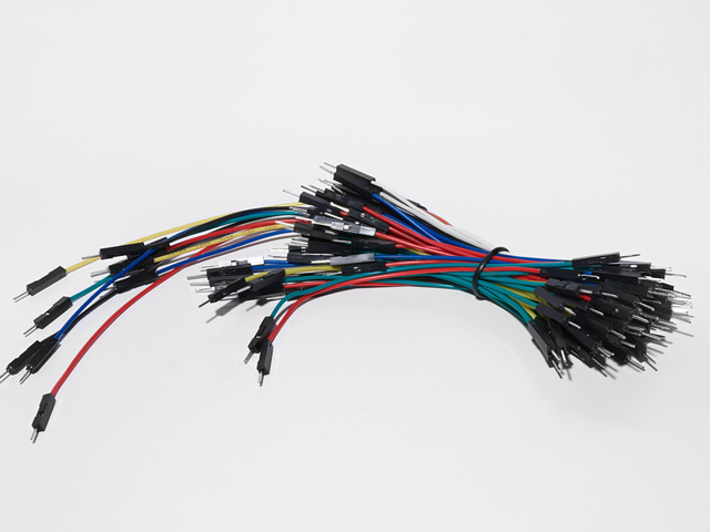
面包板接线束
如果您想从Adafruit商店订购更多电线,请单击此处!
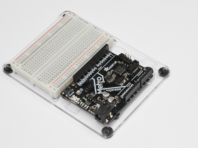
Adafruit Metro(或Metro Express)+面包板+安装板
如果您尚未组装,我们将为您提供方便的指南!
如果d想从Adafruit商店订购额外的塑料安装板,Adafruit Metro,AdafruitMetro Express或Mini-Breadboard,请点击此处!
接线
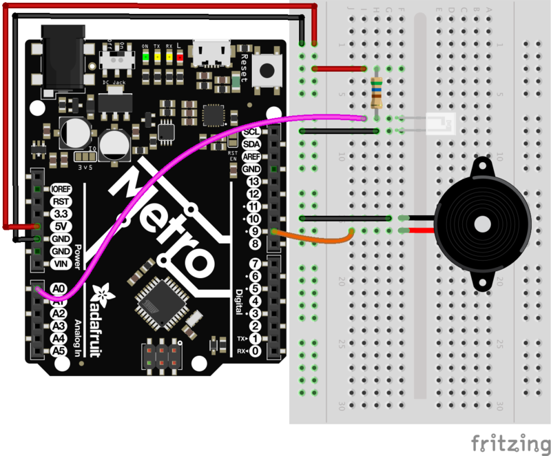
为Metro Express布线
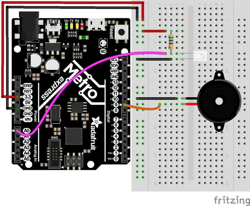
代码
设置销钉
下载:文件
复制代码
int piezoPin = 9;
int photoLightSensorPin = A0; int piezoPin = 9;
int photoLightSensorPin = A0;
压电和光传感器的引脚都声明为整数类型。光感测器前面的A代表模拟。
读取光传感器
下载:文件
复制代码
void loop() {
// get photo sensor value
int photoVal = analogRead(photoLightSensorPin);
} void loop() {
// get photo sensor value
int photoVal = analogRead(photoLightSensorPin);
}
在loop()。中读取光传感器photoVal仅用于整数值(无小数点)。然后,在光传感器引脚上调用analogRead()以读取引脚数据。
创建音高
下载:文件
复制代码
int pitch = map(photoVal, 190, 1100, 150, 1500); int pitch = map(photoVal, 190, 1100, 150, 1500);
创建音高变量以存储结果音高。然后,调用map()。此函数接受photoVal和photoVal的下限值和上限值。然后,它将范围映射到150Hz和1500Hz范围内
播放音高
下载:文件
复制代码
// play tone
tone(piezoPin, pitch); // play tone
tone(piezoPin, pitch);
Tone()传递带有压电的引脚和之前生成的音高整数。
完整的代码如下。将其复制并粘贴到空白的Arduino草图中,然后编译并上传!
下载:Project Zip 或 PROJ01_THEREMIN.ino | 在Github上查看
复制代码
/*
* (PROJ01) Metro (and Metro Express) Theremin
* Desc: Super basic theremin using a light sensor and a piezo element
*
* by Brent Rubell for Adafruit Industries.
*/
int piezoPin = 9;
int photoLightSensorPin = A0;
void setup() {
Serial.begin(9600);
}
void loop() {
// get photo sensor value
int photoVal = analogRead(photoLightSensorPin);
/* Create the pitch
* map() the photolightsensor value to
* a frequency from 150Hz to 1500Hz
* more info about map() - https://www.arduino.cc/en/Reference/Map
*/
int pitch = map(photoVal, 190, 1100, 150, 1500);
// play tone
tone(piezoPin, pitch);
}
在电路上移动手以与音乐一起播放音乐!恭喜,您刚刚建立了第一个任务电路。
这让您感到厌烦吗?让我们变得更好!
等等。。.我的项目不起作用!
我什么也没听到
检查压电和光传感器的接线。您可能会发现将光传感器翻转即可修复它。
我根本无法正常工作
我们将帮助您!在Adafruit支持论坛中发布,我们将尽快与您联系。
变得更好
修改音高
看看Theremin任务回路中map()的工作原理,您可以开始了解地图的工作原理:
map(value, fromLow, fromHigh, toLow, toHigh); 到map(photoVal, 190, 1100, 150, 1500);
前两个值对应于光传感器,而后两个是间距。尝试上下修改最后两个值(150和1500)。每次您都会得到不同的声音!
停止音乐!
您可能已经讨厌从那里发出的怪异声音了。停止声音的方法有两种。
一种方法是使用按钮。将其中一个插入面包板并连接至数字引脚2:
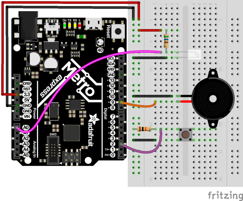
下一步,在按下按钮时将Arduino代码修改为callNoTone()。我们将由您自己决定。一个提示是同时查看NoTone()文档和CIRC07的代码。
PROJ02:MetroPOV显示
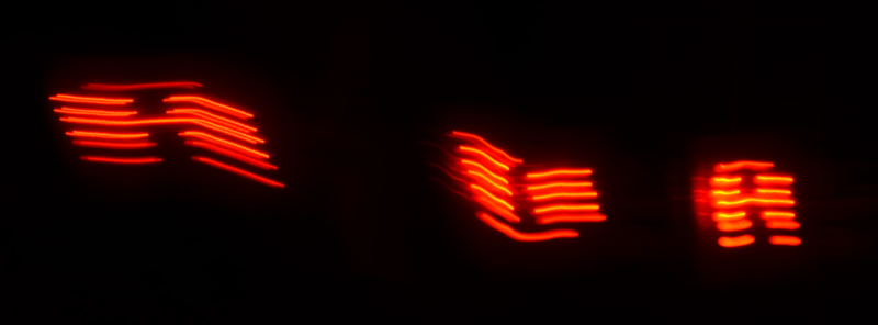
视野持久是指当从物体发出的光线停止进入眼睛后一段时间内对物体的视觉感知没有停止时发生的视觉幻觉(此处更多关于视觉的持久性)。
Adafruit制作的很酷的套件之一是MiniPOV 4,一种DIY全彩POV显示器。 MiniPOV创造了这种幻觉,并允许您在空中用光绘画。在此任务中,您将创建 MetroPOV ,该电路使用视觉持久性和Adafruit Metro。您将了解视觉的持久性,错觉,并创建自己的绘图。
让我们用Metro来绘制天空!
零件
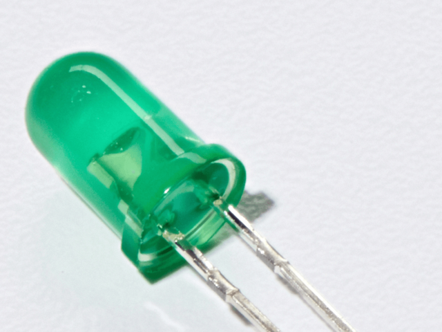
5毫米红色LED
如果您想在Adafruit商店订购更多红色LED(它们会发出很好的指示灯!),请点击这里!
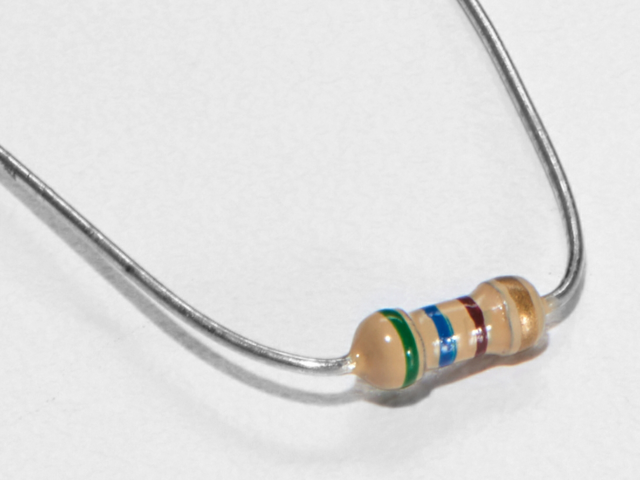
560欧姆电阻
颜色:绿色》蓝色》棕色
如果您要从Adafruit商店订购更多电阻,请点击这里! (它们的电阻为470欧姆,但可以用)
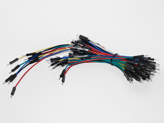
面包板接线束
如果您想从Adafruit商店订购更多电线,请单击此处!
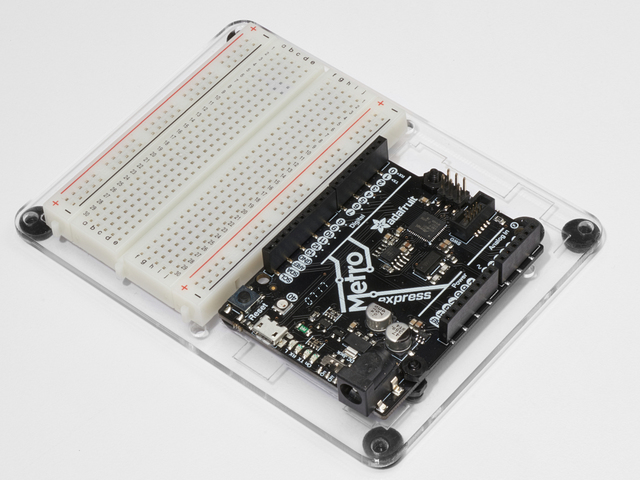
Adafruit Metro(或Metro Express)+面包板+安装板
如果您尚未组装,我们将为您提供方便的指南!
如果d想从Adafruit商店订购额外的塑料安装板,Adafruit Metro,AdafruitMetro Express或Mini-Breadboard,请点击此处!
接线
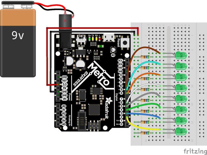
试验板的电路类似于CIRC02的布局。我们建议使用红色5mm LED或绿色5mm LED。选择您喜欢的颜色并使用它!
该电路的9V电池+夹子非常方便。您可以使用双面胶带将其粘贴在安装板的背面。
代码
将以下代码复制并粘贴到Arduino IDE中。然后,编译并将其上传到您的Metro。
下载:Project Zip 或PROJ02_METROPOV.ino | 在Github上查看
复制代码
/*
* (PROJ03) Metro (and Metro Express) Persistence of Vision Display
* Desc: POV display for Metro & Metro Express using 7x LEDs and 7x 560ohm Resistors
*
* by Brent Rubell for Adafruit Industries. Support Open Source, buy Adafruit!
*/
int spacer[8][5] = {
{0, 0, 0, 0, 0},
{0, 0, 0, 0, 0},
{0, 0, 0, 0, 0},
{0, 0, 0, 0, 0},
{0, 0, 0, 0, 0},
{0, 0, 0, 0, 0},
{0, 0, 0, 0, 0},
{0, 0, 0, 0, 0}
};
int A[8][5] = {
{0, 1, 1, 1, 0},
{1, 1, 0, 1, 1},
{1, 1, 0, 1, 1},
{1, 1, 1, 1, 1},
{1, 1, 0, 1, 1},
{1, 1, 0, 1, 1},
{1, 1, 0, 1, 1},
{0, 0, 0, 0, 0}
};
int B[8][5] = {
{1, 1, 1, 1, 0},
{1, 1, 0, 1, 1},
{1, 1, 0, 1, 1},
{1, 1, 1, 1, 0},
{1, 1, 0, 1, 1},
{1, 1, 0, 1, 1},
{1, 1, 1, 1, 0},
{0, 0, 0, 0, 0}
};
int C[8][5] = {
{0, 1, 1, 1, 0},
{1, 1, 0, 1, 1},
{1, 1, 0, 0, 0},
{1, 1, 0, 0, 0},
{1, 1, 0, 0, 0},
{1, 1, 0, 1, 1},
{0, 1, 1, 1, 0},
{0, 0, 0, 0, 0}
};
int D[8][5] = {
{1, 1, 1, 0, 0},
{1, 1, 0, 1, 1},
{1, 1, 0, 1, 1},
{1, 1, 0, 1, 1},
{1, 1, 0, 1, 1},
{1, 1, 0, 1, 1},
{1, 1, 1, 1, 0},
{0, 0, 0, 0, 0}
};
int E[8][5] = {
{1, 1, 1, 1, 1},
{1, 1, 0, 0, 0},
{1, 1, 0, 0, 0},
{1, 1, 1, 1, 0},
{1, 1, 0, 0, 0},
{1, 1, 0, 0, 0},
{1, 1, 1, 1, 1},
{0, 0, 0, 0, 0}
};
int F[8][5] = {
{1, 1, 1, 1, 1},
{1, 1, 0, 0, 0},
{1, 1, 0, 0, 0},
{1, 1, 1, 1, 0},
{1, 1, 0, 0, 0},
{1, 1, 0, 0, 0},
{1, 1, 0, 0, 0},
{0, 0, 0, 0, 0}
};
int G[8][5] = {
{0, 1, 1, 1, 0},
{1, 1, 0, 1, 1},
{1, 1, 0, 0, 0},
{1, 1, 0, 1, 1},
{1, 1, 0, 1, 1},
{1, 1, 0, 0, 1},
{0, 1, 1, 1, 1},
{0, 0, 0, 0, 0}
};
int H[8][5] = {
{1, 1, 0, 1, 1},
{1, 1, 0, 1, 1},
{1, 1, 0, 1, 1},
{1, 1, 1, 1, 1},
{1, 1, 0, 1, 1},
{1, 1, 0, 1, 1},
{1, 1, 0, 1, 1},
{0, 0, 0, 0, 0}
};
int I[8][5] = {
{0, 0, 0, 0, 0},
{1, 1, 1, 1, 1},
{0, 0, 1, 0, 0},
{0, 0, 1, 0, 0},
{0, 0, 1, 0, 0},
{0, 0, 1, 0, 0},
{1, 1, 1, 1, 1},
{0, 0, 0, 0, 0}
};
int J[8][5] = {
{0, 0, 0, 1, 1},
{0, 0, 0, 1, 1},
{0, 0, 0, 1, 1},
{0, 0, 0, 1, 1},
{1, 0, 0, 1, 1},
{1, 0, 0, 1, 1},
{0, 1, 1, 0, 0},
{0, 0, 0, 0, 0}
};
int K[8][5] = {
{0, 0, 0, 0, 0},
{1, 0, 0, 1, 0},
{1, 0, 1, 0, 0},
{1, 1, 0, 0, 0},
{1, 1, 0, 0, 0},
{1, 0, 1, 0, 0},
{1, 0, 0, 1, 0},
{0, 0, 0, 0, 0}
};
int L[8][5] = {
{1, 1, 0, 0, 0},
{1, 1, 0, 0, 0},
{1, 1, 0, 0, 0},
{1, 1, 0, 0, 0},
{1, 1, 0, 0, 0},
{1, 1, 1, 1, 1},
{1, 1, 1, 1, 1},
{0, 0, 0, 0, 0}
};
int M[8][5] = {
{1, 0, 0, 0, 1},
{1, 1, 0, 1, 1},
{1, 0, 1, 0, 1},
{1, 0, 1, 0, 1},
{1, 0, 1, 0, 1},
{1, 0, 1, 0, 1},
{1, 0, 1, 0, 1},
{0, 0, 0, 0, 0}
};
int N[8][5] = {
{1, 0, 0, 0, 1},
{1, 1, 0, 0, 1},
{1, 0, 1, 0, 1},
{1, 0, 0, 1, 1},
{1, 0, 0, 0, 1},
{1, 0, 0, 0, 1},
{1, 0, 0, 0, 1},
{0, 0, 0, 0, 0}
};
int O[8][5] = {
{1, 1, 1, 1, 1},
{1, 0, 0, 0, 1},
{1, 0, 0, 0, 1},
{1, 0, 0, 0, 1},
{1, 0, 0, 0, 1},
{1, 0, 0, 0, 1},
{1, 1, 1, 1, 1},
{0, 0, 0, 0, 0}
};
int P[8][5] = {
{1, 1, 1, 1, 0},
{1, 0, 0, 0, 1},
{1, 0, 0, 0, 1},
{1, 1, 1, 1, 0},
{1, 0, 0, 0, 0},
{1, 0, 0, 0, 0},
{1, 0, 0, 0, 0},
{0, 0, 0, 0, 0}
};
int Q[8][5] = {
{0, 1, 1, 1, 0},
{1, 0, 0, 0, 1},
{1, 0, 0, 0, 1},
{1, 0, 0, 0, 1},
{1, 0, 1, 0, 1},
{1, 0, 0, 1, 0},
{0, 1, 1, 0, 1},
{0, 0, 0, 0, 0}
};
int R[8][5] = {
{1, 1, 1, 1, 0},
{1, 0, 0, 1, 0},
{1, 0, 0, 1, 0},
{1, 1, 1, 1, 0},
{1, 1, 0, 0, 0},
{1, 0, 1, 0, 0},
{1, 0, 0, 1, 0},
{0, 0, 0, 0, 0}
};
int S[8][5] = {
{0, 1, 1, 1, 1},
{0, 1, 0, 0, 1},
{0, 1, 0, 0, 0},
{0, 0, 1, 0, 0},
{0, 0, 0, 1, 0},
{1, 0, 0, 1, 0},
{1, 1, 1, 1, 0},
{0, 0, 0, 0, 0}
};
int T[8][5] = {
{1, 1, 1, 1, 1},
{1, 0, 1, 0, 1},
{1, 0, 1, 0, 1},
{0, 0, 1, 0, 0},
{0, 0, 1, 0, 0},
{0, 0, 1, 0, 0},
{0, 0, 1, 0, 0},
{0, 0, 0, 0, 0}
};
int U[8][5] = {
{1, 0, 0, 0, 1},
{1, 0, 0, 0, 1},
{1, 0, 0, 0, 1},
{1, 0, 0, 0, 1},
{1, 0, 0, 0, 1},
{1, 0, 0, 0, 1},
{1, 1, 1, 1, 1},
{0, 0, 0, 0, 0}
};
int V[8][5] = {
{1, 0, 0, 0, 1},
{1, 0, 0, 0, 1},
{1, 0, 0, 0, 1},
{1, 0, 0, 0, 1},
{1, 0, 0, 0, 1},
{0, 1, 0, 1, 0},
{0, 0, 1, 0, 0},
{0, 0, 0, 0, 0}
};
int W[8][5] = {
{1, 0, 0, 0, 1},
{1, 0, 0, 0, 1},
{1, 0, 0, 0, 1},
{1, 0, 0, 0, 1},
{1, 0, 1, 0, 1},
{1, 0, 1, 0, 1},
{1, 1, 1, 1, 1},
{0, 0, 0, 0, 0}
};
int X[8][5] = {
{1, 0, 0, 0, 1},
{0, 1, 0, 1, 0},
{0, 0, 1, 0, 0},
{0, 0, 1, 0, 0},
{0, 1, 0, 1, 0},
{1, 0, 0, 0, 1},
{0, 0, 0, 0, 0},
{0, 0, 0, 0, 0}
};
int Y[8][5] = {
{0, 0, 0, 0, 0},
{0, 0, 0, 0, 0},
{0, 1, 0, 1, 0},
{0, 1, 0, 1, 0},
{0, 1, 1, 1, 0},
{0, 0, 1, 0, 0},
{0, 0, 1, 0, 0},
{0, 0, 0, 0, 0}
};
int Z[8][5] = {
{0, 0, 0, 0, 0},
{1, 1, 1, 1, 1},
{0, 0, 0, 1, 1},
{0, 0, 1, 1, 0},
{0, 1, 1, 0, 0},
{1, 1, 0, 0, 0},
{1, 1, 1, 1, 1},
{0, 0, 0, 0, 0}
};
// LED pins
int LEDPins[] = {2, 3, 4, 5, 6, 7, 8, 9};
// space between the letters
float letterSpacing = 0.5;
void setup() {
// start serialmon.
Serial.begin(9600);
// set all leds to output mode
for (int pin = 0; pin 《 8; pin++) {
pinMode(LEDPins[pin], OUTPUT);
}
}
void loop() {
printLetter(M);
printLetter(spacer);
printLetter(E);
printLetter(spacer);
printLetter(T);
printLetter(spacer);
printLetter(R);
printLetter(spacer);
printLetter(O);
printLetter(spacer);
// delay 2s
delay(2);
}
// outputs a letter to the POV Display
void printLetter(int letter[8][5]) {
// row of letter array
for (int j = 0; j 《 5; j++)
{
Serial.print(“ Row # ”);
Serial.print(j);
Serial.println(“。”);
// column of letter array
for (int i = 0; i 《 8; i++) {
// check for 1 within column6
if (letter[i][j] == 1) {
Serial.println(“1 detected”);
digitalWrite(LEDPins[i], HIGH);
}
else {
Serial.println(“0 detected”);
digitalWrite(LEDPins[i], LOW);
}
}
delay(letterSpacing);
}
}
我需要帮助
我无法很好地了解正在运行的MetroPOV
尝试检查本指南的下一部分。我们建议一些技巧,甚至是一个应用程序。
我看不到LED以不同的模式点亮
检查接线,LED已连接到引脚2、3、4、5、6、7、8和9在Metro或Metro Express上
什么也没做,我什么也没做
别担心,请在Adafruit支持论坛上发布,我们会尽快与您联系。
使用MetroPOV
拍照 strong》
要获取正在运行的MetroPOV的照片有点棘手。我们提供了一些技巧来帮助您拍摄MetroPOV:
稳定性和快门速度:将快门保持打开状态(我们发现2英寸到4英寸是一个很好的时限)或在应用商店中寻找长时间曝光的应用。由于相机的传感器/快门处于打开状态,因此保持相机稳定很重要。使用三脚架,或将其放置在坚固的桌子上。
保持照明状态:要获取在其中运行的MetroPOV的优质照片非常困难。明亮的环境。等待夜间或找一个黑暗的房间(为本指南拍照时,我们使用了一个关闭所有灯光的房间)。
将您的MetroPOV文本GIF添加
您可以通过组合多个长在您选择的照片编辑器中一起曝光照片。我们还使用Pablo(一种适用于iOS和Android的出色的光绘应用程序)获得了成功。调整设置(尤其是快门速度和曝光),直到找到看起来不错的设置。
使用MetroPOV进行光绘

拍摄照片时的错误通常可以产生精美的艺术品。尝试使用MetroPOV绘制字母并四处移动。在有人为您拍照时骑滑板,在椅子上旋转。实验并尝试不同的技术和想法!
PROJ03:音乐盒
音乐盒是发条的机械乐器,打开后会播放音乐。 您将把音乐盒带入21世纪-而不是通过修改金属圆柱体来对音乐盒进行编程,而是将一首优美的歌曲编程到Metro上。打开时,音乐盒会播放一首歌曲,并且LCD会在播放时显示音符。
该项目可通过以下几种方式进行自定义:您可以使用自己的盒子(也许有一个珠宝盒,一个旧的雪茄盒或Adafruit盒)和/或编程自己的音乐。
零件
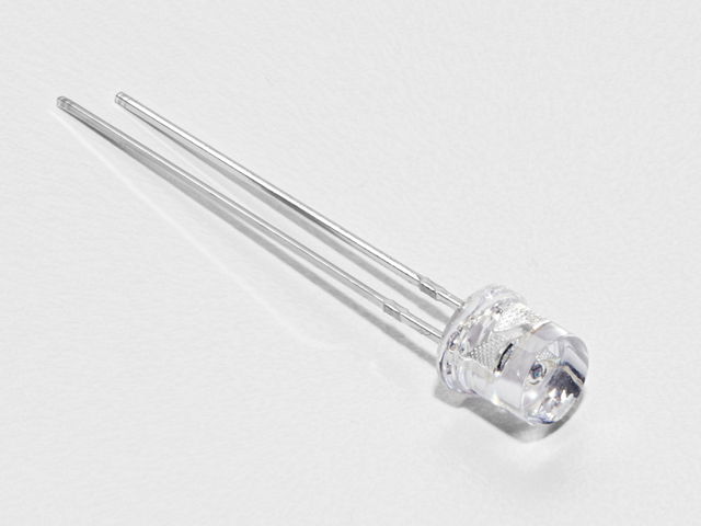
照片传感器
如果您想从Adafruit商店订购其他光敏电阻,请单击此处!
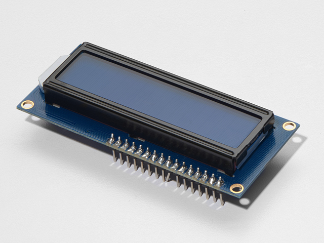
16x2字符LCD
如果您想从Adafruit商店购买蓝白色的16x2字符液晶显示器,请单击此处!
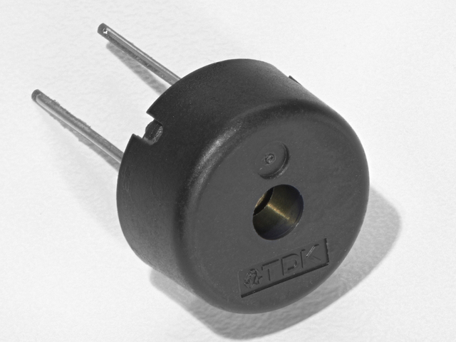
Piezo 蜂鸣器
如果您想从Adafruit商店订购另一个Pizeo Buzzer,请单击此处!
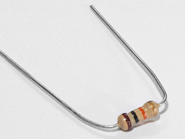
10K欧姆电阻
颜色:棕色》黑色》橙色
如果您想从Adafruit商店订购更多的10k欧姆上拉电阻,请单击此处!
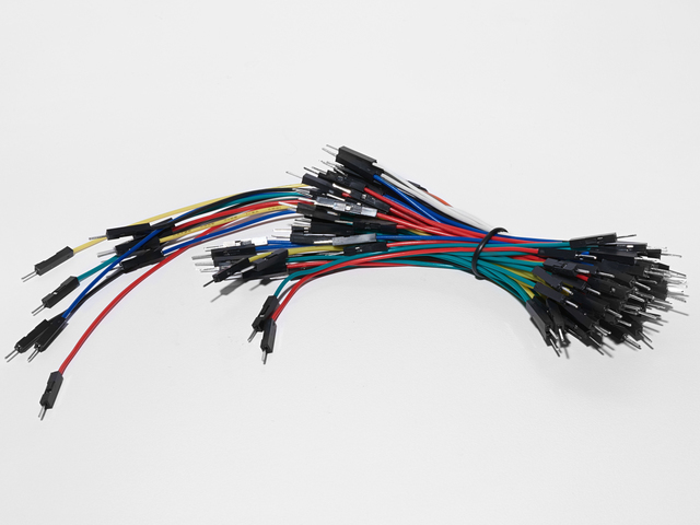
面包板接线束
如果您想从Adafruit商店订购更多电线,请点击此处!
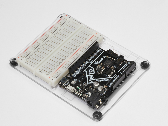
Adafruit Metro(或Metro Express)+面包板+安装板
如果您尚未组装此手册,我们将为您提供方便的指南!
如果您想订购额外的pla stic安装板,Adafruit Metro,AdafruitMetro Express或Adafruit Shop中的Mini-Breadboard单击此处!
接线
图
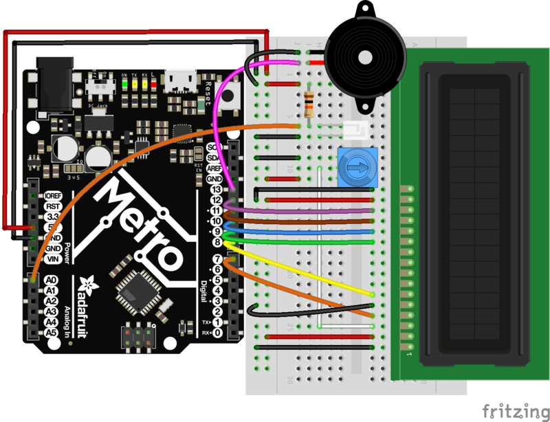
程序集
如果要使用Adafruit框(或
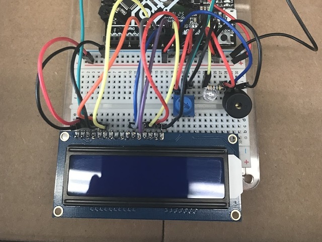
首先,将电路放置在盒子的中央。您可以将其固定下来以暂时固定。
确保光传感器未被电线挡住。
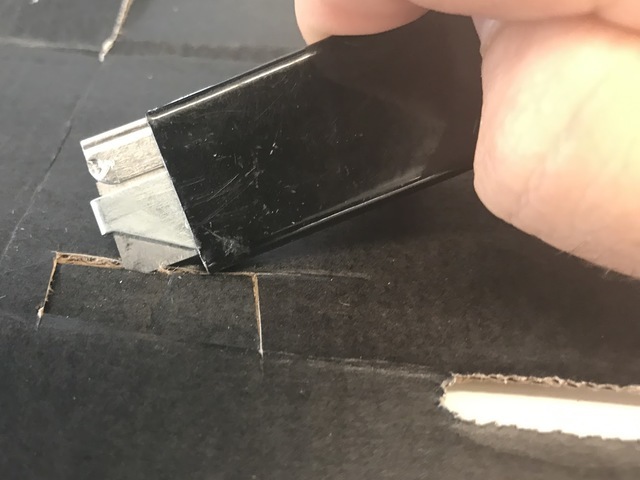
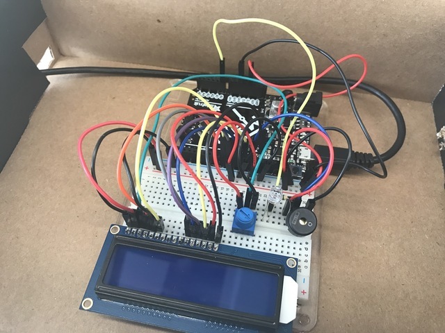
最后,将电线穿过所切的孔并将其连接到Metro。
代码
校准音乐盒
为了获得准确的读数,请关闭音乐盒并运行下面的代码。然后,打开您的串行监视器。它应该输出亮度,这是盒子会得到的最暗的亮度,因此我们将校准该值。
在您的代码中,更改以下行:
int dark = 650;-》 int dark = your measured value
重新运行代码时,当关闭框时,串行监视器应打印“框已关闭。。” 。如果您将背光源连接到引脚13,则LCD背光源也应关闭。
下载: Project Zip 或 PROJ03_MUSIC_BOX.ino | 在Github上查看
复制代码
/*
* (PROJ03) Metro (and Metro Express!) Music Box
* Desc: 21st century music box: Plays a melody when the box is open.
* Circuit: Piezo, 16x2 LCD, Photo Light Sensor
*
* by Brent Rubell for Adafruit Industries. Support Open Source Hardware, buy Adafruit!
*
*/
// include the lcd library code
#include
// initialize the library with the numbers of the interface pins
LiquidCrystal lcd(7, 8, 9, 10, 11, 12);
// Piezo code.
int speakerPin = 5;
int length = 15; // the number of notes
char notes[] = “ccggaagffeeddc ”; // a space represents a rest
int beats[] = { 1, 1, 1, 1, 1, 1, 2, 1, 1, 1, 1, 1, 1, 2, 4 };
int tempo = 300;
// Photo Light Sensor Pin
int lightPin = 0;
// Measured Darkness
int dark = 650;
// LCD Backlight Pin
int backlightPin = 13;
void playTone(int tone, int duration) {
for (long i = 0; i 《 duration * 1000L; i += tone * 2) {
digitalWrite(speakerPin, HIGH);
delayMicroseconds(tone);
digitalWrite(speakerPin, LOW);
delayMicroseconds(tone);
}
}
void playNote(char note, int duration) {
char names[] = { ’c‘, ’d‘, ’e‘, ’f‘, ’g‘, ’a‘, ’b‘, ’C‘ };
int tones[] = { 1915, 1700, 1519, 1432, 1275, 1136, 1014, 956 };
// play the tone corresponding to the note name
for (int i = 0; i 《 8; i++) {
if (names[i] == note) {
playTone(tones[i], duration);
}
}
}
void setup() {
// set up the serial monitor
Serial.begin(9600);
// set up the LCD’s cols/rows
lcd.begin(16, 2);
// set speaker as an output
pinMode(speakerPin, OUTPUT);
// set lcd backlight as an output
pinMode(backlightPin, OUTPUT);
}
void loop() {
// read the lightLevel
int lightLevel = analogRead(lightPin);
Serial.println(“Light Level -》 ”);
Serial.println(lightLevel);
// check lightLevel against dark level (should be set manually by the user, check serial mon.)
if(lightLevel 《 dark)
{
// Box is OPEN!
digitalWrite(backlightPin, HIGH);
lcd.clear();
Serial.println(“Box open, playing music!”);
for (int i = 0; i 《 length; i++) {
if(notes[i] == ‘ ’) {
// rest
delay(beats[i] * tempo);
// print a space to indicate a rest
lcd.print(“ ”);
}
else {
// play notes in notes[]
playNote(notes[i], beats [i] * tempo);
// display current note on the lcd
lcd.print(notes[i]);
}
// pause between notes
delay(tempo/2);
}
}
else{
// box is closed
// turn LCD off
digitalWrite(backlightPin, LOW);
lcd.clear();
lcd.print(“box closed.。。”);
Serial.println(“Box closed, don‘t play music.”);
}
}
遇到问题吗?
我的液晶显示器什么都不显示。
查看CIRC14中的LCD接线指南,以仔细检查所有接线是否正确。
我的音乐盒仍然过于敏感,或者不是足够敏感。
int dark 直接控制环境的黑暗或明亮在您音乐盒内。如果您发现它触发得太容易,请减小其值。
它仍然不起作用
我们将帮助您!在Adafruit支持论坛中发布,我们将尽快与您联系。
变得更好
您的音乐盒无聊吗?要添加到该电路上吗?这里有一些想法供您跳板并学习过程中的新技能
音乐作曲家
编写自己的旋律并成为作曲家,或改编一首较老的歌曲以在压电板上播放。 ( tip :检查CIRC06的“变得更好”部分以获取有关压电扬声器的更多详细信息)
非常规机箱
有成千上万种封装电子项目的方法!使用非常规的外壳(例如雪茄盒)既可以保护您的项目,又可以使其看起来更好。尝试使用其他盒子来保存您的音乐盒。
提示:要使用带有光传感器的新盒子,您应该改变什么?看看代码部分。
答案:需要重新校准光传感器。将int dark的值更改为新的Dark值。
Annoy-a-Box
想用这个电路烦扰您的朋友和家人吗?更改代码以使用高音调的呜呜声,或使哔声像蜜蜂一样在音调之间移动。
div》秘密消息框
您需要将秘密消息传递给某人,但写得太久了。时间敏感的框是一个传递给朋友,同学或国际间谍的框,其中的字符LCD上包含秘密消息。
工作原理:在打开消息窗口时,计时器开始倒计时液晶显示屏第二行上剩余的时间。计时器用完后,字符lcd清除消息,您无法再次显示该消息。
PROJ04:Fidget微调器转速表
固定旋转器是可以缓解压力的有趣玩具。它们在轴承上旋转,并且可以达到真正高每分钟转数(RPM)。我们将为您的坐骑微调器构建一个转速表,用于测量RPM。
我们在Tony D的原始Circuit Playground坐骑微调器代码中包含了一些有趣的功能
》
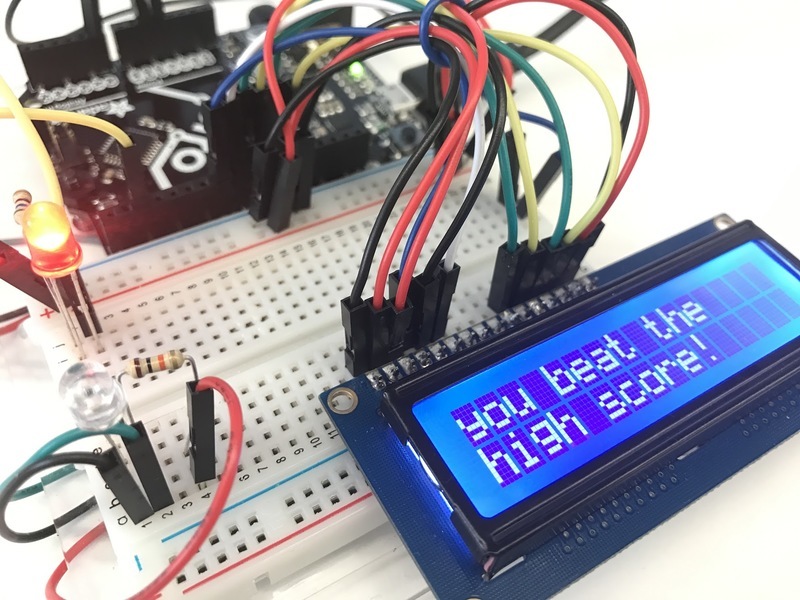
像RPM高分游戏,可与您的朋友竞争(或使不同的微调器相互竞争)
还有一个倒计时时钟,可让您更好地计时旋转。
零件
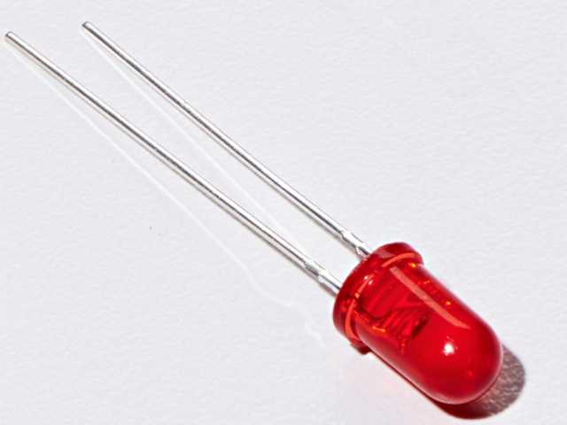
5毫米红色LED
如果您想在Adafruit商店订购更多红色LED(它们会发出很好的指示灯!),请点击这里!

照片传感器
如果您想从Adafruit商店订购其他光敏电阻,请单击此处!
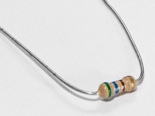
560欧姆电阻
颜色: 绿色》蓝色》棕色
如果您想从Adafruit商店请点击这里! (它们的电阻为470欧姆,但可以用)
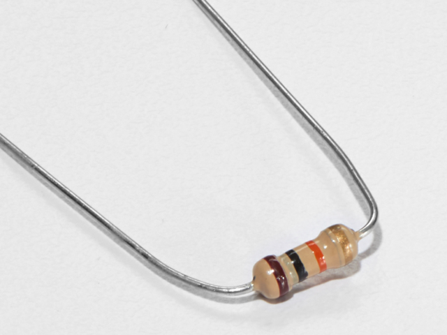
10K欧姆电阻
颜色:棕色》黑色》橙色
如果您想从Adafruit商店订购更多的10k欧姆上拉电阻,请单击此处!
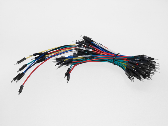
面包板接线束
如果您愿意要从Adafruit商店订购更多电线,请点击此处!
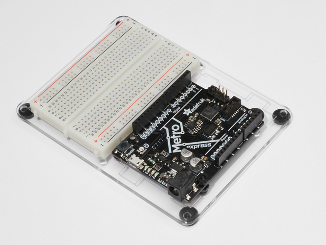
Adafruit Metro(或Metro Express)+面包板+安装板
如果尚未组装,请如果您想从Adafruit商店订购额外的塑料安装板,Adafruit Metro,AdafruitMetro Express或Mini-Breadboard,请点击这里!
接线
图
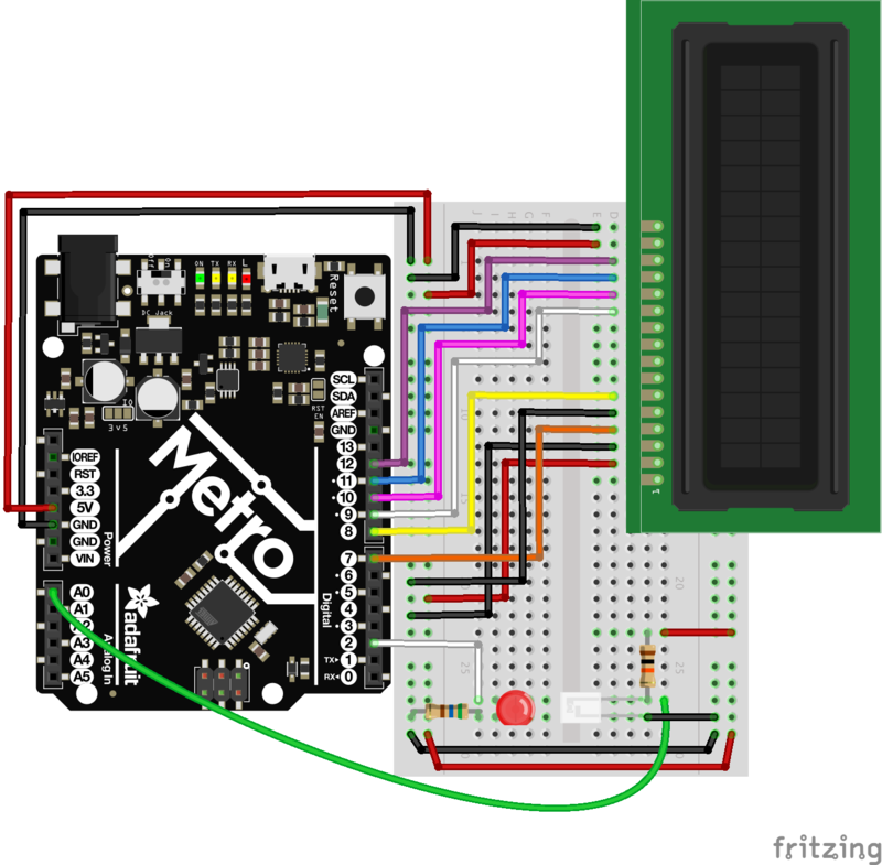
组装提示
固定旋转器喜欢以高RPM将电线从面包板上撕下。本节详细介绍如何避免这种情况的发生。
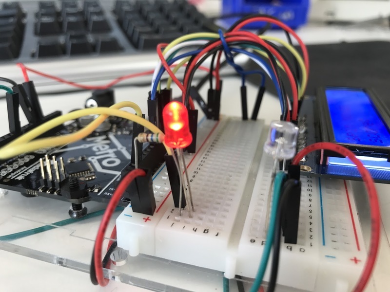
此接线涉及一些清理工作。细纱机缠在电线上。我们试图通过利用您套件中的零件来使清理工作尽可能简单。
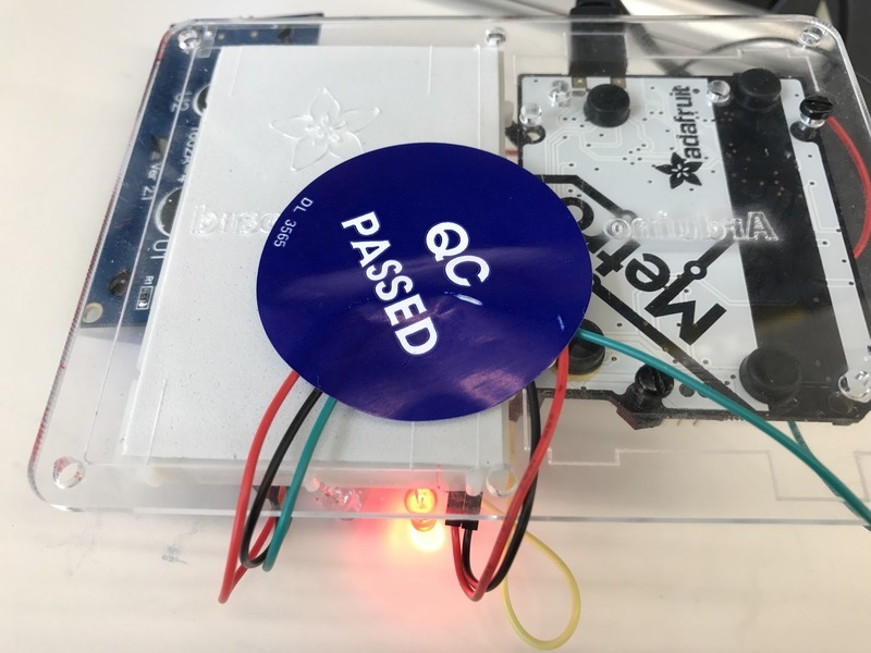
首先,让我们清理旋转区。光传感器和LED之间的区域是旋转器移动的区域。我们建议使用面包板电线束中包含的长电线。将电线塞在板子下面,并用一条胶带(或在我们的情况下,使用质量控制标签)将其固定。
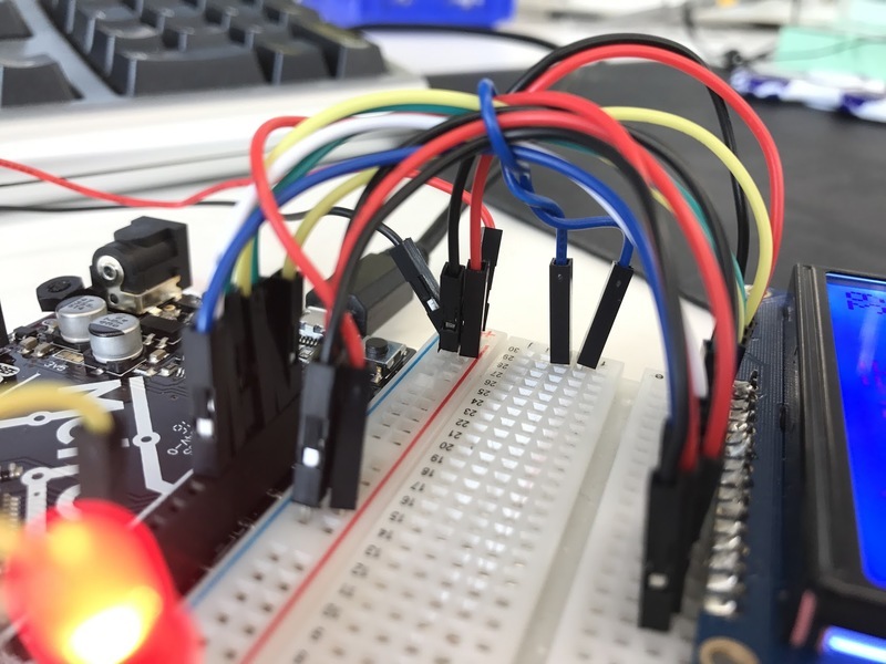
下一步,取一条较短的面包板电线,将其包裹在LCD的电线周围。您也可以使用拉链结来固定。将此线的末端插入面包板。
代码
将以下代码复制/粘贴到空白的Arduino草图中。然后,编译并将其上传到您的Metro。如果您看到LED在脚本中运行,请继续下一页。如果您没有看到它正常运行,请查看下面的常见问题以寻求帮助。
下载: Project Zip 或 PROJ04_TACHOMETER.ino | 在Github上查看
复制代码
/*
* (PROJ04) Metro (and Metro Express!) Fidget Spinner Tachometer
* Desc: Count fidget spinner RPMs (and beat your high scores)
*
* Original code by Tony Dicola for Adafruit Industries
* by Brent Rubell and Asher Lieber for the Metro Explorers Guide
*/
// include the LCD library code:
#include
// initialize the library with the numbers of the interface pins
LiquidCrystal lcd(7, 8, 9, 10, 11, 12);
// How many arms does the spinner have?
#define SPINNER_ARMS 3
// 1kB sample size
#define SAMPLE_DEPTH 256
// delay between light samples
#define SAMPLE_PERIOD_US 150
// min. speed, depends on reflective-ness of spinner, noise thresh.
//#define THRESHOLD 127
// wait 2s between measurements
#define MEASURE_PERIOD_MS 2000
// rpm high score
float rpmHighScore = 0.00;
// threshold value
int threshold;
// photo light sensor pin
int photoSensor = A0;
// led pin
int led = 2;
void setup() {
// Init. serial monitor @ 115200 baud
Serial.begin(9600);
// set up the LCD’s number of columns and rows:
lcd.begin(16, 2);
lcd.print(“Metro Tachometer”);
// set up LED
pinMode(led, OUTPUT);
}
void loop() {
int sensorCalibrate = 0;
// Set depending on light balance
threshold = 40;
// PAUSE between measurements
lcd.clear();
lcd.print(“GET READY.。。”);
analogWrite(led, 255);
// pause between sampling sensor
// shown as a countdown on the screen!
for (int i = 3500; i 》 0; i--) {
lcd.setCursor(0,1);
lcd.print(i/100);
}
// init. empty sample array
uint16_t samples[SAMPLE_DEPTH] = {0};
// start time
uint32_t start = micros();
// lcd during spin
lcd.clear();
lcd.print(“SPIN IT”);
lcd.setCursor(0,1);
lcd.print(“score: ”);
lcd.setCursor(10,1);
lcd.print(rpmHighScore);
for (int i = 0; i 《 SAMPLE_DEPTH; i++) {
// sample the photo light sensor
samples[i] = analogRead(photoSensor);
// serial output
Serial.print(“ Sample: ”);
Serial.print(samples[i]);
// keep the player occupied while sampling
if (i == int(SAMPLE_DEPTH/4)) {
lcd.clear();
lcd.print(“keep going!”);
lcd.setCursor(10,1);
lcd.print(rpmHighScore);
}
else if (i == int(SAMPLE_DEPTH/3)) {
lcd.clear();
lcd.print(“almost there!”);
lcd.setCursor(10,1);
lcd.print(rpmHighScore);
}
delayMicroseconds(SAMPLE_PERIOD_US);
}
// time elapsed (uS)
uint32_t elapsed_uS = micros() - start;
// time elapsed (sec)
float elapsed = elapsed_uS / 1000000.0;
// Find the min and max values in the collected samples.
uint16_t minval = samples[0];
uint16_t maxval = samples[0];
for (int i=1; i minval = min(minval, samples[i]);
maxval = max(maxval, samples[i]);
}
// Serial Monitor Values
Serial.print(“ Samples taken, : ”);
Serial.print(elapsed, 3);
Serial.print(“ seconds”);
Serial.print(“ Max Sample Val: ”);
Serial.print(maxval);
Serial.print(“ Min Sample Val: ”);
Serial.print(minval);
// Check the amplitude of the signal (difference between min and max)
// is greater than the threshold to continue detecting speed.
uint16_t amplitude = maxval - minval;
if (amplitude 《 threshold) {
// Didn‘t make it past the threshold so start over with another measurement attempt.
lcd.clear();
lcd.println(“didnt spin fast enough, re-spin!”);
Serial.print(“ DIDNT PASS THRESHOLD, RE-TAKING MEASUREMENT.。”);
return;
}
// Compute midpoint of the signal (halfway between min and max values)。
uint16_t midpoint = minval + (amplitude/2);
// Count how many midpoint crossings were found in the signal.
// These are instances where two readings either straddle or land on
// the midpoint. The midpoint crossings will happen twice for every
// complete sine wave cycle (once going up and again coming down)。
int crossings = 0;
for (int i=1; i uint16_t p0 = samples[i-1];
uint16_t p1 = samples[i];
if ((p1 == midpoint) ||
((p0 《 midpoint) && (p1 》 midpoint)) ||
((p0 》 midpoint) && (p1 《 midpoint))) {
crossings += 1;
}
}
// Compute signal frequency, RPM, and period.
// The period is the amount of time it takes for a complete
// sine wave cycle to occur. You can calculate this by dividing the
// amount of time that elapsed during the measurement period by the
// number of midpoint crossings cut in half (because each complete
// sine wave cycle will have 2 midpoint crossings)。 However since
// fidget spinners have multiple arms you also divide by the number
// of arms to normalize the period into a value that represents the
// time taken for a complete revolution of the entire spinner, not
// just the time between one arm and the next.
Serial.print(“ MP Crossings: ”);
Serial.print(crossings);
Serial.print(“ Elapsed: ”);
Serial.print(elapsed);
float period = elapsed / (crossings / 2.0 / SPINNER_ARMS);
Serial.print(“ Period: ”);
Serial.print(period);
// Once the period is calculated it can be converted into a frequency
// value (i.e revolutions per second, how many times the spinner spins
// around per second) and more common RPM value (revolutions per minute,
// just multiply frequency by 60 since there are 60 seconds in a minute)。
float frequency = 1.0 / period;
float rpm = frequency * 60.0;
// Print out the measured values!
Serial.print(“Frequency: ”);
Serial.print(frequency, 3);
Serial.print(“ (hz) RPM: ”);
Serial.print(rpm, 3);
Serial.print(“ Period: ”);
Serial.print(period, 3);
Serial.println(“ (seconds)”);
lcd.clear();
lcd.setCursor(1,0);
lcd.print(rpm);
delay(2000);
// high score checker
if(rpm 》 rpmHighScore) {
rpmHighScore = rpm;
lcd.clear();
lcd.setCursor(0,0);
lcd.print(“you beat the”);
lcd.setCursor(0,1);
lcd.print(“high score!”);
delay(2000);
}
}
LCD为空白/乱码/毛刺
确保所有电线均正确插入且没有松动。在将所有东西绑在一起的组装步骤中,请确保所有东西都紧紧插入Metro和面包板中。
LED无法打开?
检查LED接线。可能是电阻值错误。
仍然无法正常工作吗?
在我们的社区支持论坛上发布!
零件
这是Metro Express项目。
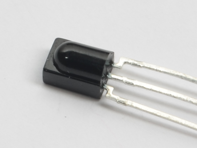
红外传感器
使用方式:红外传感器接收并解码进入的红外。
如果要从Adafruit商店订购额外的红外接收器传感器,请单击此处!

小型遥控器
用法:迷你遥控器将发送 红外信号到连接到Metro M0 Express的红外传感器。
如果想要从Adafruit商店订购额外的迷你遥控器,请单击此处!
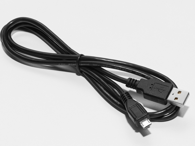
迷你USB电缆
请确保您使用的迷你USB电缆充电+数据而不仅仅是充电。
如果您想从Adafruit商店订购Mini-USB电缆,请点击此处
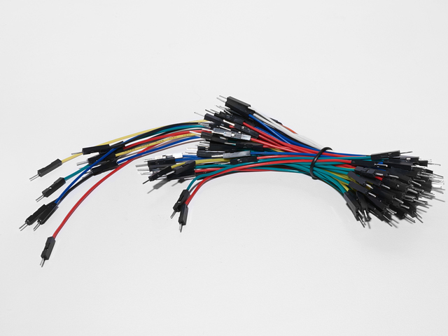
面包板接线束
如何使用:我们将把电源线,地线和数据线连接到红外传感器的3个引脚上。
如果您要要从Adafruit商店订购更多电线,请点击此处!
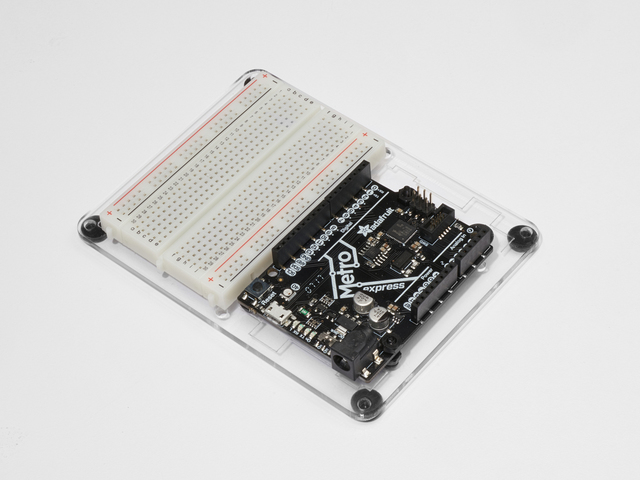
Adafruit Metro Express +面包板+安装板
如果您尚未组装此指南,那么我们将为您提供方便的指南!
需要aextra塑料安装板,Adafruit MetroExpress或Mini-Breadboard Adafruit商店?
接线
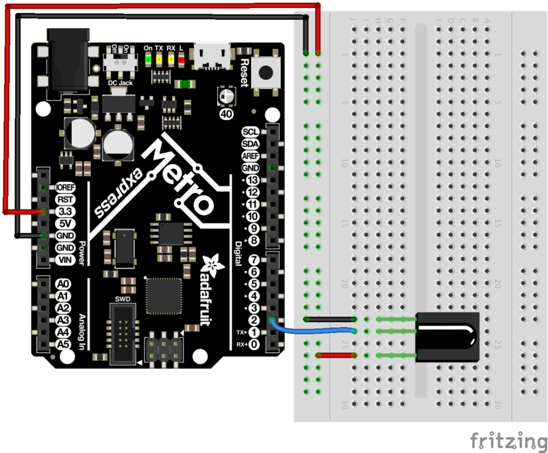
代码
对于该项目,我们将同时使用IRLib和Keyboard库,因此,让我们弄清楚如何组合它们。本节是自学的,因为我们将逐段为您提供代码,您可以继续学习。
首先,我们希望同时包括IRLibAll和键盘库:
下载:文件
复制代码
#include
#include #include
#include
然后,我们将包含按钮代码。由于这些都是长整数,因此它们被编码为十六进制值-Colin在此处提供了有关此主题的精彩视频。
下载:文件
复制代码
/* Remote Codes */
#define VOLUMEUP 0xfd40bf
#define VOLUMEDOWN 0xfd00ff
#define RIGHT_ARROW 0xfd50af
#define LEFT_ARROW 0xfd10ef
#define PLAYPAUSE 0xfd807f
#define SELECT_BUTTON 0xfd906f
/* Remote Codes */
#define VOLUMEUP 0xfd40bf
#define VOLUMEDOWN 0xfd00ff
#define RIGHT_ARROW 0xfd50af
#define LEFT_ARROW 0xfd10ef
#define PLAYPAUSE 0xfd807f
#define SELECT_BUTTON 0xfd906f
我们将NEC定义为Adafruit Mini遥控器,然后在数字引脚2上创建一个接收器。之后,创建一个解码器对象和一个整数,以保存NEC重复代码的先前代码。
下载:文件
复制代码
// Adafruit Mini-Remote uses NEC, change this if you’re using a different remote
#define MY_PROTOCOL NEC
// receiver on pin 2
IRrecv myReceiver(2);
// Decoder object
IRdecode myDecoder;
// NEC repeat codes for Adafruit Mini-Remote
uint32_t Previous; // Adafruit Mini-Remote uses NEC, change this if you‘re using a different remote
#define MY_PROTOCOL NEC
// receiver on pin 2
IRrecv myReceiver(2);
// Decoder object
IRdecode myDecoder;
// NEC repeat codes for Adafruit Mini-Remote
uint32_t Previous;
最后,我们要在引脚13上创建一个LED对象,它是内置LED。我们将使用这种方法在视觉上调试电路,而无需打印到串行监视器。
下载:文件
复制代码
const int ledPin = 13; const int ledPin = 13;
在setup()循环中,我们要进行告诉Metro开始控制键盘,启动IR接收器,并将led配置为输出。
下载:文件
复制代码
void setup() {
// initialize control over the keyboard
Keyboard.begin();
// start the IR receiver
myReceiver.enableIRIn();
// configure status LED
pinMode(LED_BUILTIN, OUTPUT);
} void setup() {
// initialize control over the keyboard
Keyboard.begin();
// start the IR receiver
myReceiver.enableIRIn();
// configure status LED
pinMode(LED_BUILTIN, OUTPUT);
}
loop()非常复杂,但我们将其分解以使其更容易。我们将首先检测接收器是否使用myReceiver.getResults()从遥控器获得输入。然后,我们将通过调用myDecoder.decode()对其进行解码。
接下来,我们要检查协议是否与Mini Remote NEC所使用的协议相同,请检查if(myDecoder.protocolNum==MY_PROTOCOL)。最后,我们将检测重复代码,并将当前值设置为先前的解码值if(myDecoder.value==0xFFFFFFFF {myDecoder.value=Previous;}
下载:文件
复制代码
void loop()
{
if (myReceiver.getResults()) {
myDecoder.decode();
if(myDecoder.protocolNum==MY_PROTOCOL) {
if(myDecoder.value==0xFFFFFFFF)
myDecoder.value=Previous;
// handle everything in here void loop()
{
if (myReceiver.getResults()) {
myDecoder.decode();
if(myDecoder.protocolNum==MY_PROTOCOL) {
if(myDecoder.value==0xFFFFFFFF)
myDecoder.value=Previous;
// handle everything in here
Phew,现在有趣的部分开始了。我们将使用称为SwitchCase的编程概念。这将使我们接受一个值(由解码器解码的值-myDecode.value),并根据值是什么来执行不同的操作。
,我们将根据myDecoder.value进行切换。第一种情况是是否检测到“ PLAYPAUSE”按钮(已在上面#define定义)。我们要发送空格键来暂停VLC播放。
下载:file
复制代码
switch(myDecoder.value) {
case PLAYPAUSE:
// key-play-pause
// send the spacebar key
switch(myDecoder.value) {
case PLAYPAUSE:
// key-play-pause
// send the spacebar key
我们将使用Keyboard.write()。将空格键ascii值0x20发送到键盘然后,我们将使LED发光以指示已发送密钥(这是一种非常简单的可视化代码调试方式)。接下来,我们将延迟,然后调用Keyboard.releaseAll();释放按下的键。然后,在这种情况下,我们将break;并完成执行。
下载:文件
复制代码
Keyboard.write((char)0x20);
digitalWrite(LED_BUILTIN, HIGH);
delay(100);
// release the keys pressed
Keyboard.releaseAll();
break; Keyboard.write((char)0x20);
digitalWrite(LED_BUILTIN, HIGH);
delay(100);
// release the keys pressed
Keyboard.releaseAll();
break;
现在您已经有了主意,我们将为您提供代码。如果您想更好地理解这个项目,请尝试使之更好部分。
下载:Project Zip 或 PROJ05_IR_MEDIA_CONTROLLER.ino | 在Github上查看
复制代码
/* PROJ05: Metro Media Remote
* Desc: Control VLC with your Adafruit Metro M0 Express!
* by Brent Rubell and Asher Liber for Adafruit Industries
* Requires IRLib2.x Library
*/
#include
#include
/* Remote Codes */
#define VOLUMEUP 0xfd40bf
#define VOLUMEDOWN 0xfd00ff
#define RIGHT_ARROW 0xfd50af
#define LEFT_ARROW 0xfd10ef
#define PLAYPAUSE 0xfd807f
#define SELECT_BUTTON 0xfd906f
// These are some extra button codes.。.not used in the PROJ.
// if you want to create more functions in VLC or any other app, use these!
#define UP_ARROW 0xfda05f
#define DOWN_ARROW 0xfdb04f
#define BUTTON_0 0xfd30cf
#define BUTTON_1 0xfd08f7
#define BUTTON_2 0xfd8877
#define BUTTON_3 0xfd48b7
#define BUTTON_4 0xfd28d7
#define BUTTON_5 0xfda857
#define BUTTON_6 0xfd6897
#define BUTTON_7 0xfd18e7
#define BUTTON_8 0xfd9867
#define BUTTON_9 0xfd58a7
// Adafruit Mini-Remote uses NEC, change this if you’re using a different remote
#define MY_PROTOCOL NEC
// receiver on pin 2
IRrecv myReceiver(2);
// Decoder object
IRdecode myDecoder;
// NEC repeat codes for Adafruit Mini-Remote
uint32_t Previous;
// use this option for OSX:
char ctrlKey = KEY_LEFT_GUI;
// use this option for Windows and Linux:
// char ctrlKey = KEY_LEFT_CTRL;
const int ledPin = 13;
void setup() {
// monitor the serial at 9600baud
Serial.begin(9600);
// initialize control over the keyboard
Keyboard.begin();
// start the IR receiver
myReceiver.enableIRIn();
// configure status LED
pinMode(LED_BUILTIN, OUTPUT);
Serial.println(“Listening to IR.。。”);
}
void loop()
{
if (myReceiver.getResults()) {
myDecoder.decode();
if(myDecoder.protocolNum==MY_PROTOCOL) {
if(myDecoder.value==0xFFFFFFFF)
myDecoder.value=Previous;
// We used VLC for this example, but you can use any keyboard shortcuts!
// (src: https://wiki.videolan.org/Hotkeys_table/)
switch(myDecoder.value) {
case PLAYPAUSE:
// key-play-pause
// send the spacebar key
Keyboard.write((char)0x20);
digitalWrite(LED_BUILTIN, HIGH);
delay(100);
// release the keys pressed
Keyboard.releaseAll();
break;
case VOLUMEUP:
// key-vol-up
// vlc shortcut: ctrl + up arrow
Keyboard.press(ctrlKey);
Keyboard.press(KEY_UP_ARROW);
digitalWrite(LED_BUILTIN, HIGH);
delay(100);
Keyboard.releaseAll();
break;
case VOLUMEDOWN:
// key-vol-down
// vlc shortcut: ctrl + down arrow
Keyboard.press(ctrlKey);
Keyboard.press(KEY_DOWN_ARROW);
digitalWrite(LED_BUILTIN, HIGH);
delay(100);
Keyboard.releaseAll();
break;
case RIGHT_ARROW:
// key-faster
// vlc shortcut: +
Keyboard.press(‘+’);
digitalWrite(LED_BUILTIN, HIGH);
delay(100);
Keyboard.releaseAll();
break;
case LEFT_ARROW:
// key-faster
// vlc shortcut: -
Keyboard.press(‘-’);
digitalWrite(LED_BUILTIN, HIGH);
delay(100);
Keyboard.releaseAll();
break;
default:
// if nothing else matches, do the default
// default is optional
break;
}
Previous=myDecoder.value;
}
digitalWrite(LED_BUILTIN, LOW);
myReceiver.enableIRIn();
}
}
/* PROJ05: Metro Media Remote
* Desc: Control VLC with your Adafruit Metro M0 Express!
* by Brent Rubell and Asher Liber for Adafruit Industries
* Requires IRLib2.x Library
*/
#include
#include
/* Remote Codes */
#define VOLUMEUP 0xfd40bf
#define VOLUMEDOWN 0xfd00ff
#define RIGHT_ARROW 0xfd50af
#define LEFT_ARROW 0xfd10ef
#define PLAYPAUSE 0xfd807f
#define SELECT_BUTTON 0xfd906f
// These are some extra button codes.。.not used in the PROJ.
// if you want to create more functions in VLC or any other app, use these!
#define UP_ARROW 0xfda05f
#define DOWN_ARROW 0xfdb04f
#define BUTTON_0 0xfd30cf
#define BUTTON_1 0xfd08f7
#define BUTTON_2 0xfd8877
#define BUTTON_3 0xfd48b7
#define BUTTON_4 0xfd28d7
#define BUTTON_5 0xfda857
#define BUTTON_6 0xfd6897
#define BUTTON_7 0xfd18e7
#define BUTTON_8 0xfd9867
#define BUTTON_9 0xfd58a7
// Adafruit Mini-Remote uses NEC, change this if you‘re using a different remote
#define MY_PROTOCOL NEC
// receiver on pin 2
IRrecv myReceiver(2);
// Decoder object
IRdecode myDecoder;
// NEC repeat codes for Adafruit Mini-Remote
uint32_t Previous;
// use this option for OSX:
char ctrlKey = KEY_LEFT_GUI;
// use this option for Windows and Linux:
// char ctrlKey = KEY_LEFT_CTRL;
const int ledPin = 13;
void setup() {
// monitor the serial at 9600baud
Serial.begin(9600);
// initialize control over the keyboard
Keyboard.begin();
// start the IR receiver
myReceiver.enableIRIn();
// configure status LED
pinMode(LED_BUILTIN, OUTPUT);
Serial.println(“Listening to IR.。。”);
}
void loop()
{
if (myReceiver.getResults()) {
myDecoder.decode();
if(myDecoder.protocolNum==MY_PROTOCOL) {
if(myDecoder.value==0xFFFFFFFF)
myDecoder.value=Previous;
// We used VLC for this example, but you can use any keyboard shortcuts!
// (src: https://wiki.videolan.org/Hotkeys_table/)
switch(myDecoder.value) {
case PLAYPAUSE:
// key-play-pause
// send the spacebar key
Keyboard.write((char)0x20);
digitalWrite(LED_BUILTIN, HIGH);
delay(100);
// release the keys pressed
Keyboard.releaseAll();
break;
case VOLUMEUP:
// key-vol-up
// vlc shortcut: ctrl + up arrow
Keyboard.press(ctrlKey);
Keyboard.press(KEY_UP_ARROW);
digitalWrite(LED_BUILTIN, HIGH);
delay(100);
Keyboard.releaseAll();
break;
case VOLUMEDOWN:
// key-vol-down
// vlc shortcut: ctrl + down arrow
Keyboard.press(ctrlKey);
Keyboard.press(KEY_DOWN_ARROW);
digitalWrite(LED_BUILTIN, HIGH);
delay(100);
Keyboard.releaseAll();
break;
case RIGHT_ARROW:
// key-faster
// vlc shortcut: +
Keyboard.press(’+‘);
digitalWrite(LED_BUILTIN, HIGH);
delay(100);
Keyboard.releaseAll();
break;
case LEFT_ARROW:
// key-faster
// vlc shortcut: -
Keyboard.press(’-‘);
digitalWrite(LED_BUILTIN, HIGH);
delay(100);
Keyboard.releaseAll();
break;
default:
// if nothing else matches, do the default
// default is optional
break;
}
Previous=myDecoder.value;
}
digitalWrite(LED_BUILTIN, LOW);
myReceiver.enableIRIn();
}
}
我对此项目项目
致命错误:IRLibAll.h:无此类文件或目录#包括
IRLib 2.x库安装不正确。检查CIRC16的“安装IR库”页面以获取正确的安装说明。
我的计算机没有响应远程
如果您使用的是Adafruit Mini-Remote,请确保取消注释(删除斜线)char ctrlKey您所使用的操作系统的变量:
// use this option for OSX:
char ctrlKey = KEY_LEFT_GUI;
// use this option for Windows and Linux:
// char ctrlKey = KEY_LEFT_CTRL;
如果使用自己的遥控器,则需要对代码进行修改。有关更多信息,请参阅本指南中的发送IR代码。
该项目仍无法正常工作
在Adafruit支持论坛中发布,我们将尽快与您联系。
变得更好
我们在最后一页提供的代码中为您添加了一些额外的按钮:
下载:文件
复制代码
// These are some extra button codes.。.not used in the PROJ.
// if you want to create more functions in VLC or any other app, use these!
#define UP_ARROW 0xfda05f
#define DOWN_ARROW 0xfdb04f
#define BUTTON_0 0xfd30cf
#define BUTTON_1 0xfd08f7
#define BUTTON_2 0xfd8877
#define BUTTON_3 0xfd48b7
#define BUTTON_4 0xfd28d7
#define BUTTON_5 0xfda857
#define BUTTON_6 0xfd6897
#define BUTTON_7 0xfd18e7
#define BUTTON_8 0xfd9867
#define BUTTON_9 0xfd58a7 // These are some extra button codes.。.not used in the PROJ.
// if you want to create more functions in VLC or any other app, use these!
#define UP_ARROW 0xfda05f
#define DOWN_ARROW 0xfdb04f
#define BUTTON_0 0xfd30cf
#define BUTTON_1 0xfd08f7
#define BUTTON_2 0xfd8877
#define BUTTON_3 0xfd48b7
#define BUTTON_4 0xfd28d7
#define BUTTON_5 0xfda857
#define BUTTON_6 0xfd6897
#define BUTTON_7 0xfd18e7
#define BUTTON_8 0xfd9867
#define BUTTON_9 0xfd58a7
如果您想在VLC中将这些命令用于不同的命令,或者控制Netflix或Youtube,请查阅Arduino修改器键文档。实施新密钥,或在SwitchCase中修改您先前存在的案例以使用其他密钥。
PROJ06:红外激光宠物玩具
您想惹恼您(或家人)的宠物吗?也许您想以最懒惰的方式锻炼宠物?您将要制造一个由红外遥控器和Adafruit Metro控制的激光宠物玩具。
这是它的工作方式:将廉价的激光笔固定在伺服喇叭。您将使用双面胶带将舵机安装到面包板上,以使其牢固。然后,将您的红外传感器与伺服器连接起来,并编写一个程序,使您可以在安全距离内烦扰/锻炼宠物
对激光和宠物的了解
激光指示器点可以同时驱使猫狗强迫行为,因为它可以找出宠物的“猎物”本能。我们强烈建议在房间周围藏一些食物,然后让IR激光宠物玩具朝食物的方向移动。 追逐自己认为是猎物的狗/猫需要奖励。
我们还建议您和您的宠物避免直接接触激光。在与动物玩耍时,请保持打开激光,以免它们望着灯(关闭/打开它会使它们迅速转过身)。
零件
该项目需要外部零件。
此项目需要激光指针。我们不建议不要使用我们在Adafruit商店中出售的Laser 二极管。您的角落商店或亚马逊出售的是功率很低的激光指针。
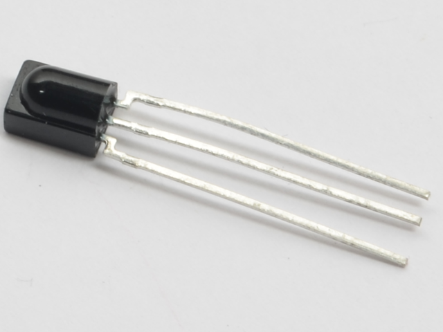
IR接收器用于接收来自遥控器的红外信号。这些信号然后将被发送到Metro,Metro将告诉伺服器将移动到何处。

Mini Remote包含一个IR LED,用于向连接到Metro M0的IR接收器传输信号。
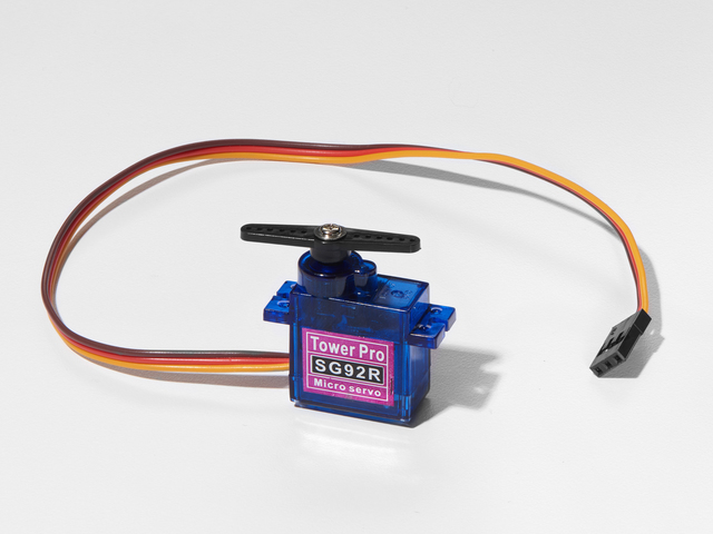
Hobby Servo将用作平台来左右旋转激光指示器。
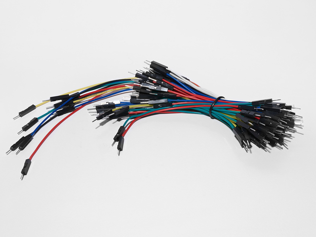
面包板接线束
如果您想从Adafruit商店订购更多电线,请点击此处!
Adafruit地铁+面包板+安装板
如果您尚未组装,我们将为您提供方便的指南!
如果您想从Adafruit商店订购额外的塑料安装板,Adafruit Metro或Mini-Breadboard,请点击此处!
接线
装配有两种方法:我们可以将激光指示器放在伺服器的顶部,然后用胶带将其打开,或者将其拆开。并在其上焊接一些引线,以便可由Metro控制。
此接线是第一种选择(非受控激光)。
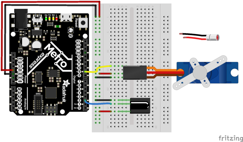
此接线用于激光器由红外遥控器控制。我们正在通过从引脚#13发送电压来控制激光器。
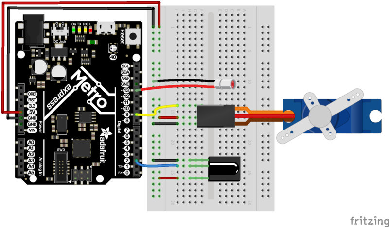
装配体
该项目需要一些装配体(例如音乐盒)才能使您获得很好的性能。
伺服接线
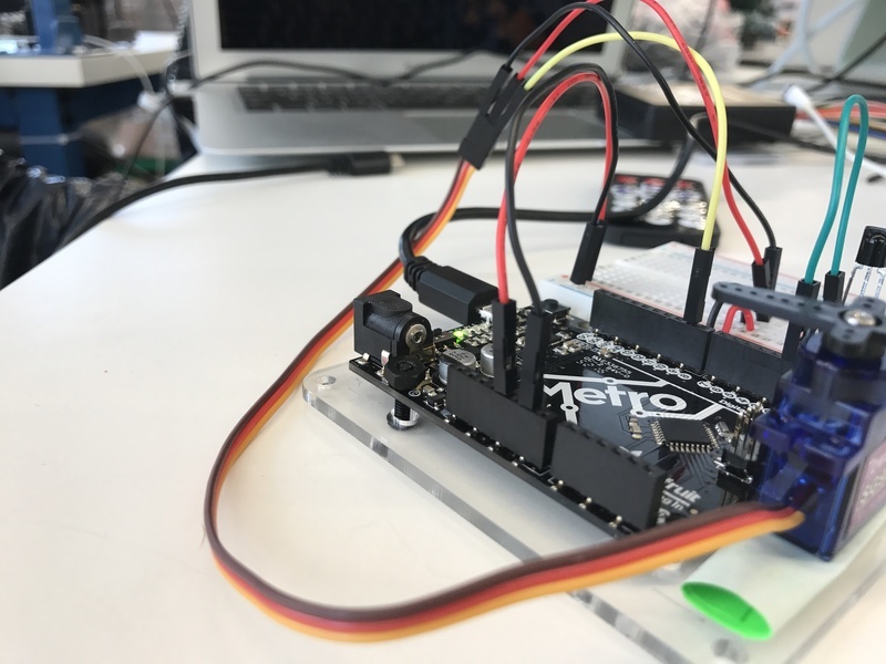
我们将对伺服器进行接线,以使面包板接线束中的电线更长被使用。我们要将伺服安装在
Base上程序集
胶带并将其折叠(或卷起来)。
然后将其放在安装板上。向下按以保持牢固的握持力(伺服机构可以非常有力地移动)。
打一条领带(如您在当地超市可以买到的领带)或一条领带,然后将激光笔固定在舵机的角上。我们喜欢使用扎带和扎带,因为它们非常便宜且不永久。
代码
此代码看起来与PROJ05非常相似-它使用类似的结构来处理IR远程按钮按下,但使用伺服器而不是USB HID 。我们还将介绍您可能在以前的CIRC中看到的三个新概念-random(),min()和max()。
首先,让我们导入两个IRLiband Servo:
下载:文件
复制代码
#include
#include #include
#include
然后,我们将包含所有特定于远程的代码。这将包括#define的远程值,接收器引脚分配,解码器对象和所使用的ir协议。
下载:文件
复制代码
/* Adafruit Mini Remote */
#define MY_PROTOCOL NEC
#define RIGHT_ARROW 0xfd50af
#define LEFT_ARROW 0xfd10ef
#define SELECT_BUTTON 0xfd906f
#define BUTTON_0 0xfd30cf
#define BUTTON_1 0xfd08f7
#define BUTTON_2 0xfd8877
#define BUTTON_3 0xfd48b7
#define BUTTON_4 0xfd28d7
#define BUTTON_5 0xfda857
#define BUTTON_6 0xfd6897
#define BUTTON_7 0xfd18e7
#define BUTTON_8 0xfd9867
#define BUTTON_9 0xfd58a7
// pin number for the receiver
IRrecv myReceiver(2);
IRdecode myDecoder;
// handles nec repeat codes
uint32_t Previous;
下一步,我们将创建伺服对象myServo,用于存储伺服位置的变量和用于保存伺服角度(以度为单位)的变量。
下载:文件
复制代码
/* Servo */
// create a servo object
Servo myServo;
// stores the servo position
int16_t pos;
// angle (degrees) to move the servo left/right
int16_t Speed;
/* Servo */
// create a servo object
Servo myServo;
// stores the servo position
int16_t pos;
// angle (degrees) to move the servo left/right
int16_t Speed;
(可选) 如果您正在使用激光并且能够在地铁上对其进行控制(请参见:组装),我们将把电源连接到引脚11。一个布尔值laserToggle,以打开和关闭激光。 laserToggle保留两个值之一- true 或 false 。根据所按下的按钮和当前状态,我们可以轻松切换激光器。
下载:文件
复制代码
/* Laser */
// connect laser PWR to a pin 11
const int laserPin = 11;
// toggle the laser
bool laserToggle = false;
/* Laser */
// connect laser PWR to a pin 11
const int laserPin = 11;
// toggle the laser
bool laserToggle = false;
我们的 setup()代码需要设置激光针作为输出,将伺服器连接到针9,将初始pos设置为90,将初始pos设置为90,将初始Speed设置为5。然后,我们将将pos写入伺服器并启动IR接收器。
下载:文件
复制代码
void setup() {
// randomizes a seed for random() calls
randomSeed(analogRead(0));
// set the laser pin as an output
pinMode(laserPin, OUTPUT);
// attach servo to pin 9
myServo.attach(9);
// set initial position
pos = 90;
// set initial speed
Speed = 5;
// write initial pos to servo at startup
myServo.write(pos);
// Start the IR receiver
myReceiver.enableIRIn();
}
如前所述,此代码类似于PROJ05:
loop()非常复杂,但是我们将对其进行分解以使其更容易。我们将首先检测接收器是否使用myReceiver.getResults()从遥控器获得输入。然后,我们将通过调用myDecoder.decode()对其进行解码。
接下来,我们要检查协议是否与Mini Remote NEC所使用的协议相同,请检查if(myDecoder.protocolNum==MY_PROTOCOL)。最后,我们将检测重复代码,并将当前值设置为先前的解码值if(myDecoder.value==0xFFFFFFFF {myDecoder.value=Previous;}
下载:文件
复制代码
void loop()
{
if (myReceiver.getResults()) {
myDecoder.decode();
if(myDecoder.protocolNum==MY_PROTOCOL) {
if(myDecoder.value==0xFFFFFFFF)
myDecoder.value=Previous;
switch(myDecoder.value) { void loop()
{
if (myReceiver.getResults()) {
myDecoder.decode();
if(myDecoder.protocolNum==MY_PROTOCOL) {
if(myDecoder.value==0xFFFFFFFF)
myDecoder.value=Previous;
switch(myDecoder.value) {
但这一次,我们要进行的是在写入伺服器之前设置伺服器的位置。业余伺服器的旋转角度特别令人难以置信,如果旋转得太远,它们可能会损坏。让我们用min()函数来防止这种情况。此功能会将伺服器的位置设置为 pos + Speed ,但会将值保持在下方或180度,以免超出该点。
下载:文件
复制代码
case LEFT_ARROW:
// move servo
pos=min(180,pos+Speed);
break; case LEFT_ARROW:
// move servo
pos=min(180,pos+Speed);
break;
类似地,如果要限制右侧,请将pos设置为max(0, pos-Speed)。 Max与min相反,则限制值的下端
下载:文件
复制代码
case RIGHT_ARROW:
pos=max(0,pos-Speed);
break; case RIGHT_ARROW:
pos=max(0,pos-Speed);
break;
Arduino允许您做的一件很酷的事就是生成一个随机数。如果调用random(0, 180),则可以生成0到180之间的随机数。让我们设置一个按钮,将pos设置为随机调用。
下载:文件
复制代码
case BUTTON_0:
pos=random(0,180);
break; case BUTTON_0:
pos=random(0,180);
break;
在case语句之后,您将要:
1。写入伺服器,
2。处理NEC重复代码:Previous=myDecoder.value;
3。重新启用IR接收器
下载:文件
复制代码
myServo.write(pos);
Previous=myDecoder.value;
myReceiver.enableIRIn();
myServo.write(pos);
Previous=myDecoder.value;
myReceiver.enableIRIn();
完整代码如下
下载:Project Zip 或 PROJ06_IR_PET.ino | 在Github上查看
复制代码
/*
Metro Explorers Guide
PROJ06 - IR Laser Pet Toy
by Brent Rubell and Asher Lieber for Adafruit Industries. Support Open Source, buy Adafruit!
Note: this sketch requires IRLIB2.x
*/
#include
#include
/* Adafruit Mini Remote */
#define MY_PROTOCOL NEC
#define RIGHT_ARROW 0xfd50af
#define LEFT_ARROW 0xfd10ef
#define SELECT_BUTTON 0xfd906f
#define BUTTON_0 0xfd30cf
#define BUTTON_1 0xfd08f7
#define BUTTON_2 0xfd8877
#define BUTTON_3 0xfd48b7
#define BUTTON_4 0xfd28d7
#define BUTTON_5 0xfda857
#define BUTTON_6 0xfd6897
#define BUTTON_7 0xfd18e7
#define BUTTON_8 0xfd9867
#define BUTTON_9 0xfd58a7
// pin number for the receiver
IRrecv myReceiver(2);
IRdecode myDecoder;
// handles nec repeat codes
uint32_t Previous;
/* Servo */
// create a servo object
Servo myServo;
// stores the servo position
int16_t pos;
// angle (degrees) to move the servo left/right
int16_t Speed;
void setup() {
// randomizes a seed for random() calls
randomSeed(analogRead(0));
// set the laser pin as an output
//pinMode(laserPin, OUTPUT);
// attach servo to pin 9
myServo.attach(9);
// set initial position
pos = 90;
// set initial speed
Speed = 5;
// write initial pos to servo at startup
myServo.write(pos);
// Start the IR receiver
myReceiver.enableIRIn();
}
void loop()
{
if (myReceiver.getResults()) {
myDecoder.decode();
if (myDecoder.protocolNum == MY_PROTOCOL) {
if (myDecoder.value == 0xFFFFFFFF)
myDecoder.value = Previous;
switch (myDecoder.value) {
case LEFT_ARROW:
// move servo
pos = min(180, pos + Speed);
break;
case RIGHT_ARROW:
pos=max(0,pos-Speed);
break;
case BUTTON_0:
pos=random(0,180);
break;
}
// tell servo ’move to variable pos‘
myServo.write(pos);
Previous=myDecoder.value;
}
myReceiver.enableIRIn();
}
}
该项目无法正常运行
我的伺服器无法正确移动
请确保您的伺服器已连接到Metro或Metro Express上的数字引脚9 。还要确保草图中包含伺服库(在草图顶部,您应该看到#include )。
《我class =“ fa fa-question-circle-o”》
我’ m使用其他遥控器,我应该做些不同的事情吗?
代码该项目仅适用于Adafruit Mini Remote。如果您想使用其他遥控器,请查阅本指南以获取更多信息。
该项目仍无法正常工作
在Adafruit支持论坛中发布,我们将尽快与您联系:)
PROJ08:模拟温度计表
Adafruit商店中最酷的产品之一是汽车仪表步进电机,这是一种带有指针指示器的步进电机。该仪表可用于物理感觉,类似于汽车的转速表。
由于我们已经有了伺服电机,因此我们可以构建一个模拟仪表来测量温度。该PROJ还可以重新用于为您可以测量的任何事物创建物理输出量规!
零件
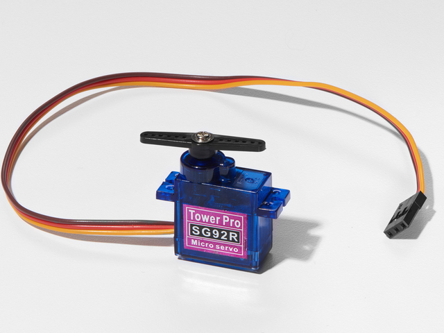
迷你伺服器
如果您想从Adafruit商店订购额外的迷你伺服器,请单击此处!
Adafruit商店中还有许多其他伺服尺寸和类型,请查看我们的产品
模拟温度传感器看起来很像NPN晶体管,请确保其上显示“ TMP36”!
模拟温度传感器
如果您想要一个额外的温度传感器,可以从Adafruit商店购买一个,单击此处
面包板接线束
如果想要从Adafruit商店订购更多电线,请点击此处!
Adafruit Metro(或Metro Express)+面包板+安装板
如果您尚未组装,我们将为您提供方便的指南!
如果您想从Adafruit商店订购额外的塑料安装板,Adafruit Metro,AdafruitMetro Express或Mini-Breadboard,请点击此处!
接线
请注意,有两个电源连接: TMP36连接到3.3V引脚,伺服连接到5V引脚。如果您使用的是常规地铁,那么两者都可以连接到 5V 引脚并通过代码进行控制。
组装
我们为此的组装过程可能会因您您想要制作电路的方式而有所不同。外壳可能有所不同,您甚至可能想尝试使用Adafruitstore中的其他伺服器。但是,校准非常重要,您需要“拨入”您的伺服器以确保它能完美显示。
在您的伺服器中拨号
首先,我们应将伺服系统移至其中心位置。下载并运行此小型Arduino代码。它将伺服移动到其中心位置:
下载:文件
复制代码
/*
* Servo Centering Script
*
*/
#include
Servo myservo;
void setup() {
myservo.attach(9);
}
void loop() {
// change this depending on where you‘re centering
myservo.write(90);
delay(15);
}
/*
* Servo Centering Script
*
*/
#include
Servo myservo;
void setup() {
myservo.attach(9);
}
void loop() {
// change this depending on where you’re centering
myservo.write(90);
delay(15);
}
您应该会看到伺服喇叭向中心移动。从伺服器上卸下喇叭(如果将其拧紧,则必须将其拧松),并用记号笔标记其顶端。这将是您的指标:
将喇叭重新安装到舵机上(现在应该处于90度位置),您就可以开始滚动了!
组装外壳
让我们建立一个外壳,以便您可以在工作中或在房间的任何地方使用它。经验丰富的Dano Wallw打造了可打印,剪裁的设计,该设计适合您的metroX套件随附的盒子顶部。这是一种双拨号设计,可与华氏温度和摄氏温度一起使用。您可以下载下面的设计(它是开源的,并且可以完全修改):
将印刷的表盘与MetroX盒子进行测试适配,然后沿黑色外线切掉
将四个角(我们只在下面的gif文件中用胶带将两个粘贴在盒子的内部。如果可以,请使用透明胶带,这样看起来会更干净:
使用盒刀或剪刀的边缘在您的印刷设计上切出伺服切口(矩形)。可能需要花一些时间才能完全了解此框:
清除切孔中的残留纸板。将伺服器朝外的方向贴在矩形孔中:
最后,您将需要一个定点设备。我们使用一次性便笺簿的内部,因为它们很便宜,很多人都把它们放在身边:
干得好!关闭框并准备编程:
代码
此代码是 CIRC04:伺服和 CIRC10:温度之间的混合代码。我们正在做的是将温度值附加到伺服值上。让我们看一下其中的一些部分:
在内部,我们将使用CIRC04的getVoltage()函数从引脚读取电压。然后,我们将这个值传递给新函数convertToF(),该函数根据电压值生成,以将电压转换为华氏温度:
下载:文件
复制代码
// read the voltage from the pin
float voltage = getVoltage(temperaturePin);
// convert the voltage to a temperature value
float temperature = convertToF(voltage); // read the voltage from the pin
float voltage = getVoltage(temperaturePin);
// convert the voltage to a temperature value
float temperature = convertToF(voltage);
然后,我们要约束温度值。这完全取决于您,您可以使用任何数字,但是我们使用-10F和100F作为TMP36接受的最低和最高温度:
map((int(temperature)), -10, 100
我们仍然需要将温度值映射到伺服值。伺服器可以移动的最小度数为 0度,最大度数为 180 ,因此我们将伺服器设置为映射:-10到0和100到180:
下载:文件
复制代码
servoPos = map((int(temperature)), -10, 100, 0, 180); servoPos = map((int(temperature)), -10, 100, 0, 180);
然后,将servoPos写入伺服器!
下载:文件
复制代码
// write servoPos to the servo
metroServo.write(servoPos);
// poll every 0.5sec
delay(500); // write servoPos to the servo
metroServo.write(servoPos);
// poll every 0.5sec
delay(500);
以下是完整的代码,其中包括内置的辅助程序:
代码
下载:Project Zip 或 PROJ07_RGB_MIXER.ino | span》 在Github上查看
复制代码
/*
* PROJ07 - RGB Color Mixer
*
* by Brent Rubell for Adafruit Industries
*/
// RGB LED Pins
int rgbLED[] = {9, 10, 11};
// trim potentiometer pin
int trimPin = A0;
// button pin
const int buttonPin = 12;
// button state
int buttonState = 0;
// trim pot. value
int trimValue = 0;
int colorIdx = 0;
int red = 0;
int green = 0;
int blue = 0;
boolean CURRENTRGB[] = {0, 0, 0};
void setup() {
// Setup Serial
Serial.begin(9600);
// set the 3 pins as output pins
for(int i = 0; i 《 3; i++) {
pinMode(rgbLED[i], OUTPUT);
}
// initialize the push-button as an input
pinMode(buttonPin, INPUT);
}
void loop() {
// read the value of the push-button
buttonState = digitalRead(buttonPin);
if(buttonState == LOW) {
delay(2);
// reset the colorIdx if it goes past Blue (colorIdx = 3)
if(colorIdx == 3) {
colorIdx = 0;
}
colorIdx++;
switch(colorIdx) {
case 1:
trimValue = analogRead(trimPin);
red = map(trimValue, 0, 670, 0, 255);
CURRENTRGB[0] = red;
break;
case 2:
trimValue = analogRead(trimPin);
green = map(trimValue, 0, 670, 0, 255);
CURRENTRGB[1] = green;
break;
case 3:
trimValue = analogRead(trimPin);
blue = map(trimValue, 0, 670, 0, 255);
CURRENTRGB[2] = blue;
break;
default:
break;
}
Serial.println(“red:”);
Serial.print(CURRENTRGB[0]);
Serial.println(“ ”);
Serial.println(“green:”);
Serial.print(CURRENTRGB[1]);
Serial.println(“ ”);
Serial.println(“blue:”);
Serial.print(CURRENTRGB[2]);
Serial.println(“ ”);
setColor(rgbLED, CURRENTRGB);
delay(1000);
}
}
void setColor(int* led, const boolean* color) {
for(int i = 0; i 《 3; i++){
digitalWrite(led[i], color[i]);
}
}
责任编辑:wv
-
Arduino
+关注
关注
184文章
6427浏览量
184826
发布评论请先 登录
相关推荐
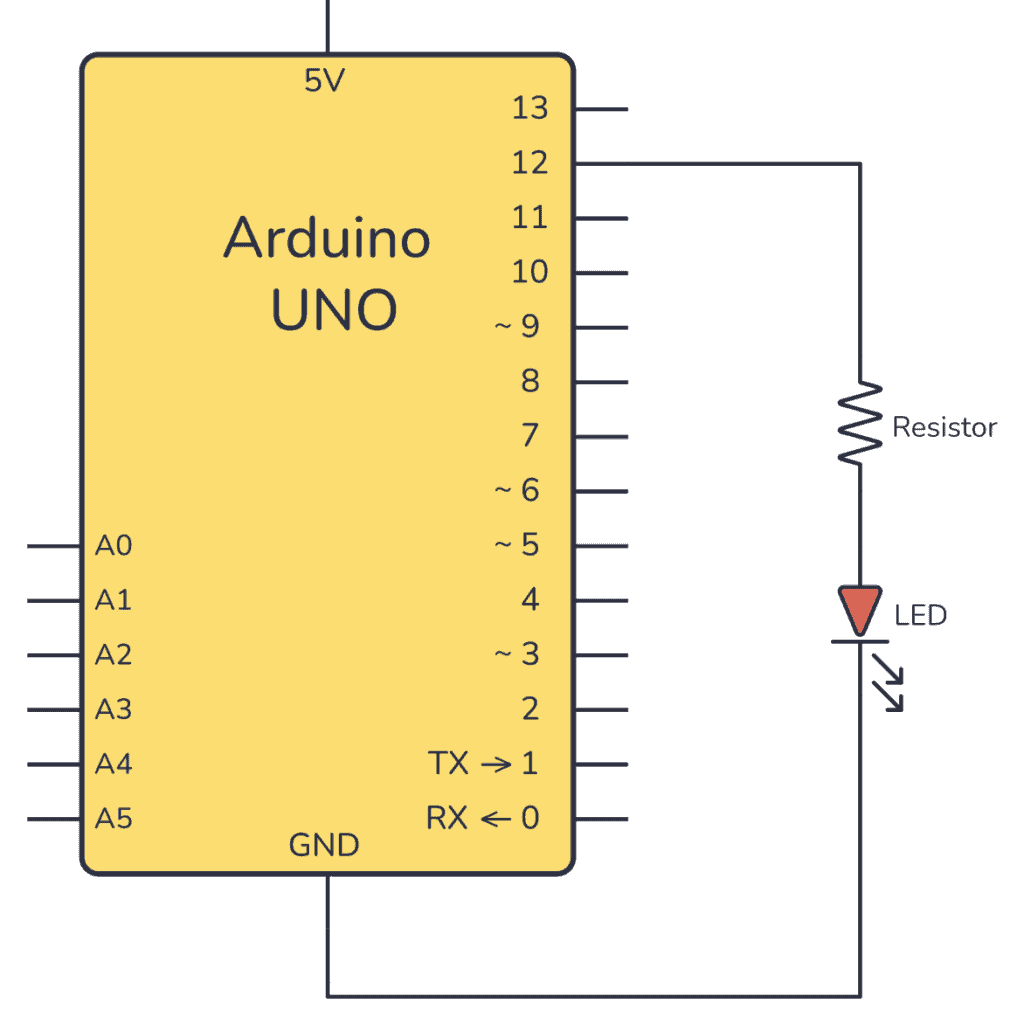
如何将光敏电阻连接到Arduino板并读取电压
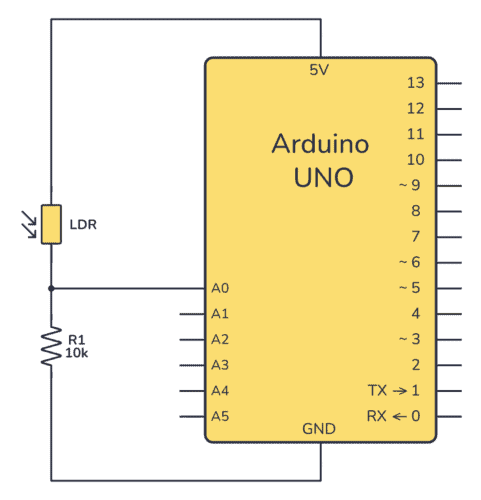
如何使用Arduino控制RGB LED
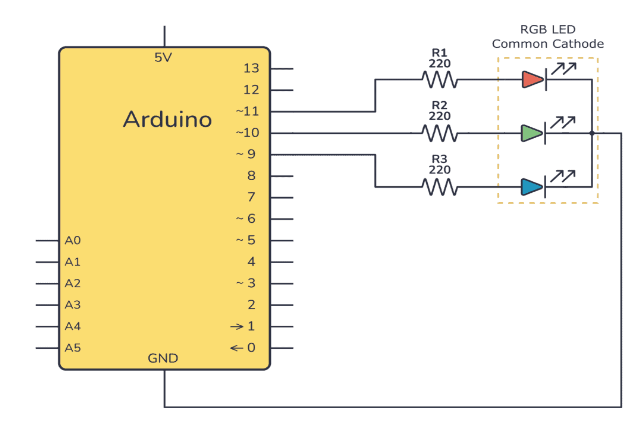
如何连接Arduino声音传感器以控制带有声音的LED
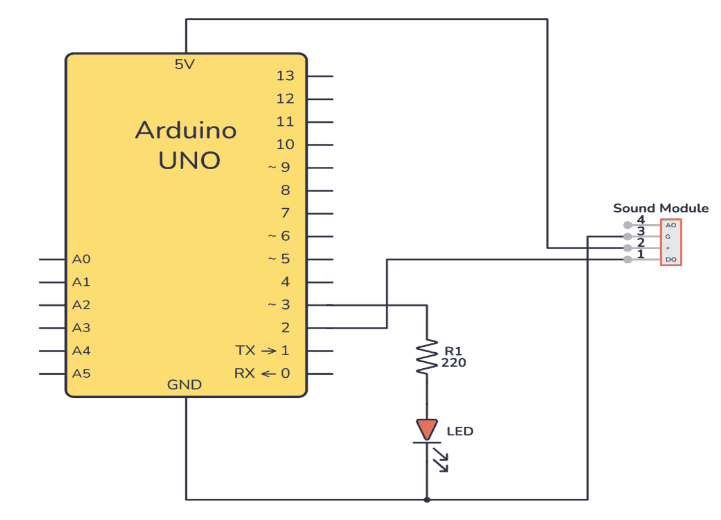
如何设置Arduino霍尔效应传感器
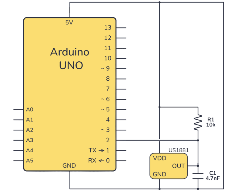
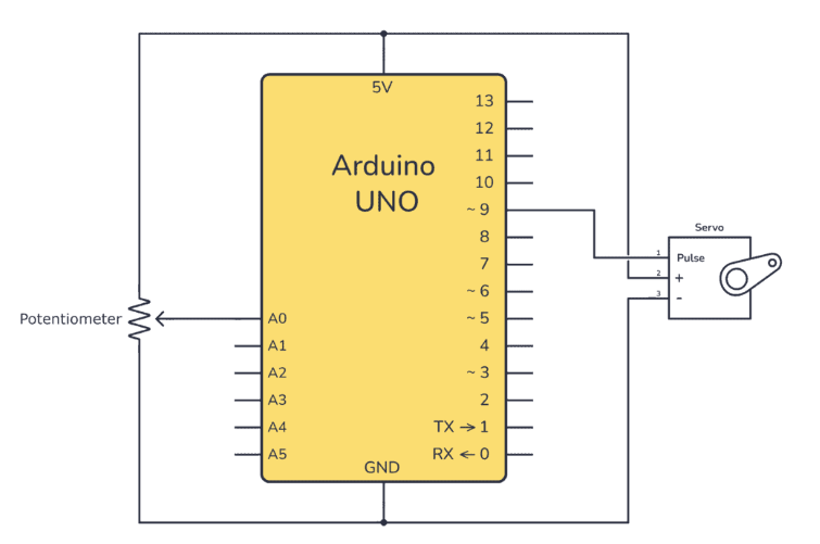
如何设置Arduino IR发射器电路
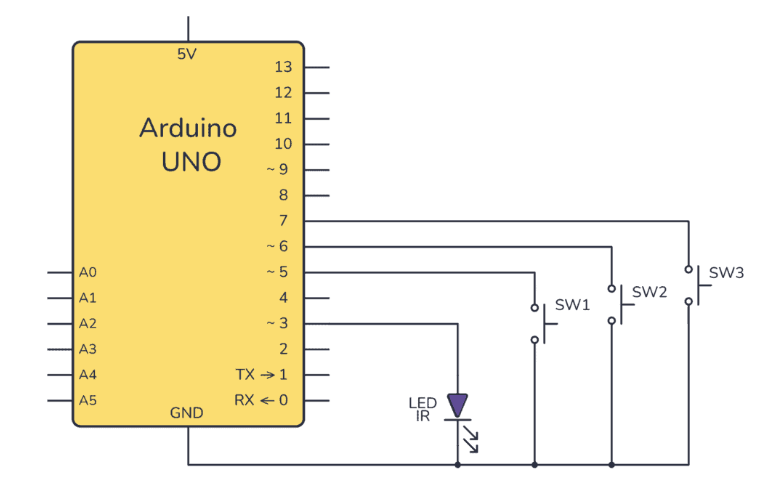
音频DAC基础技术的学习指南
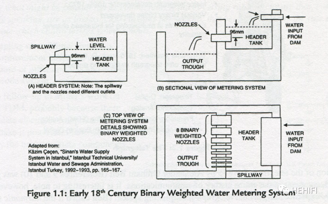
基于Arduino的机器学习开发

汽车控制器的硬件学习指南
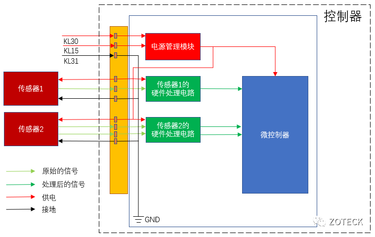
StudySmarter:使用Arduino和ML监控学习习惯


 工商网监
工商网监
评论